Language selection

Search

Patent 2065369 Summary

Third-party information liability

Some of the information on this Web page has been provided by external sources. The Government of Canada is not responsible for the accuracy, reliability or currency of the information supplied by external sources. Users wishing to rely upon this information should consult directly with the source of the information. Content provided by external sources is not subject to official languages, privacy and accessibility requirements.

Claims and Abstract availability

Any discrepancies in the text and image of the Claims and Abstract are due to differing posting times. Text of the Claims and Abstract are posted:

  • At the time the application is open to public inspection;
  • At the time of issue of the patent (grant).
(12) Patent: (11) CA 2065369
(54) English Title: SUPPORT STRUCTURE FOR THE FASTENING OF A STEAM CHEST
(54) French Title: SUPPORT DE FIXATION DE BOITE A VAPEUR
Status: Deemed expired
Bibliographic Data
(51) International Patent Classification (IPC):
  • D21F 5/08 (2006.01)
  • D21F 5/02 (2006.01)
(72) Inventors :
  • PARTIO, MARTTI ENSIO OLAVI (Finland)
(73) Owners :
  • DEUBLIN ITALIANA S.R.L. (Italy)
(71) Applicants :
(74) Agent: OYEN WIGGS GREEN & MUTALA LLP
(74) Associate agent:
(45) Issued: 1999-10-19
(86) PCT Filing Date: 1990-08-03
(87) Open to Public Inspection: 1991-03-21
Examination requested: 1997-07-18
Availability of licence: N/A
(25) Language of filing: English

Patent Cooperation Treaty (PCT): Yes
(86) PCT Filing Number: PCT/FI1990/000189
(87) International Publication Number: WO1991/004373
(85) National Entry: 1992-02-21

(30) Application Priority Data:
Application No. Country/Territory Date
894440 Finland 1989-09-20

Abstracts

English Abstract


Support structure for the steam
chest of a steam cylinder where the
fixing points for the rod supports (1) of
the old steam chest (2) are utilized
when the support plate (11) of the
fastening ring (10) of the new steam chest
(12) is mounted.


French Abstract

Structure de support pour le réservoir de vapeur d'un cylindre à vapeur dans laquelle les points de fixation pour les supports de tige (1) de l'ancien réservoir de vapeur (2) sont utilisés lorsque la plaque de support (11) de l'anneau de fixation (10) du nouveau réservoir de vapeur (12) est montée.

Claims

Note: Claims are shown in the official language in which they were submitted.


-1-


WHAT IS CLAIMED IS:


1. Support structure for fastening a chest (12) of a rotary steam joint
connected
to the end of a steam shaft (3) of a drying cylinder to a machine frame, the
chest
(12), comprising a fastening ring (10) for connection to the machine frame;
an annular support plate (11) being fastened to the machine frame utilizing
two
fixing holes (13) provided in the machine frame diametrically on opposite
sides of the
center axis of the drying cylinder;
the support plate (11) forming a mounting seat for the fastening ring (10) and
being provided with screws (14) for adjusting the center axis of the chest
(12) to
coincide with the center axis of the drying cylinder, at least two of said
screws (14)
being positioned on opposite sides of a line defined by said two fixing holes
(13).
2. Construction according to claim 1, characterized in that the support plate
(11)
of the new steam chest is fixed to the surface of the cantilever support (15)
of the old
steam chest (2).

Description

Note: Descriptions are shown in the official language in which they were submitted.


W091/04373 ',~,i'~'~~ ~'a~~~ pCf/FI90/00189
:.-.:, .
1
Support structure for the fastening of a steam chest
The construction according to the invention enables an improved
support for the steam chest of a drying cylinder against the
machine frame, and thus it is possible to install the steam chest
with substantially greater care and accuracy in comparison to
what is possible with a conventional rod support or cantilever
support.
The constructions in use presently include supplying steam to,
the drying cylinder through a steam chest fastened to the end of
the cylinder shaft (figure 1). The steam chest 2 is supported
through support bars 1 against the machine frame. Steam is
conducted to the cylinder through the steam cylinder shaft 3.
Condensate and discharge steam is conducted in the horizontal
condensate discharge pipe 4 to the condensate section of the
steam chest. There are also constructions with a connection
structure for the condensate only, so called condensate chests.
It is however common to have the steam and condensate joints in
a common steam chest. The most common construction of the steam
chest is shown in figure 2. The steam chest 2 is supported against
the machine frame with two rods 1. Figure 3 shows a cantilever
support construction 5. The drawback of the constructions
according to figures 2 and 3 is that the geometric center 6 and
center axis of the rotating parts inside the steam chest do not
coincide with the center axis 7 of the cylinder. Figures 4a and
4b. The differences of the center axes may be due to tolerances
of the machining of the steam chest support deviating from the
allowed ones. As a result the parts inside the steam chest will
wear out or suffer damage in a too short time.
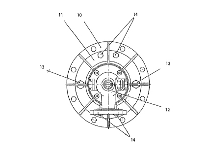
The construction according to the present invention utilizes
existing fixing points for the support of the old steam chest,
such that the steam chest 12 is supported by the support plate
11 against the machine frame, the plate being a full ring or a


WO 91/04373 ~~~;,~. ~~~ r~?~ PCT/FI90/00189
2
partial ring. Figures Sa and .5b show the construction according
to the invention. The fastening ring 10 of the steam chest 12
frame is fixed with a bolted joint to the support plate 11 fastened
to the machine frame.
The points 13 of the old steam chest rod supports are utilized
such that the support plate 11 is fastened to the machine frame
through these points. The support plate 11 is adjusted to a
correct position with adjusting screws 14 in order to firmly keep
the support plate in the correct position. With different
solutions for the adjusting screws it is possible to install the
support plate 11 on frame structures of greatly varying form.
The fixing arrangement shown in figures Sa and 5b allows the
center and the center axis of the steam chest to coincide exactly
with the cylinder axis.

Representative Drawing
A single figure which represents the drawing illustrating the invention.
Administrative Status

For a clearer understanding of the status of the application/patent presented on this page, the site Disclaimer , as well as the definitions for Patent , Administrative Status , Maintenance Fee  and Payment History  should be consulted.

Administrative Status

Title Date
Forecasted Issue Date 1999-10-19
(86) PCT Filing Date 1990-08-03
(87) PCT Publication Date 1991-03-21
(85) National Entry 1992-02-21
Examination Requested 1997-07-18
(45) Issued 1999-10-19
Deemed Expired 2001-08-03

Abandonment History

There is no abandonment history.

Payment History

Fee Type Anniversary Year Due Date Amount Paid Paid Date
Application Fee $0.00 1992-02-21
Maintenance Fee - Application - New Act 2 1992-08-03 $50.00 1992-07-17
Registration of a document - section 124 $0.00 1992-11-04
Maintenance Fee - Application - New Act 3 1993-08-03 $50.00 1993-07-20
Maintenance Fee - Application - New Act 4 1994-08-03 $50.00 1994-07-15
Maintenance Fee - Application - New Act 5 1995-08-03 $75.00 1995-07-26
Maintenance Fee - Application - New Act 6 1996-08-05 $75.00 1996-07-26
Registration of a document - section 124 $100.00 1997-06-27
Request for Examination $400.00 1997-07-18
Maintenance Fee - Application - New Act 7 1997-08-04 $150.00 1997-07-30
Maintenance Fee - Application - New Act 8 1998-08-03 $150.00 1998-07-29
Final Fee $150.00 1999-06-14
Maintenance Fee - Application - New Act 9 1999-08-03 $150.00 1999-07-23
Owners on Record

Note: Records showing the ownership history in alphabetical order.

Current Owners on Record
DEUBLIN ITALIANA S.R.L.
Past Owners on Record
PARTIO ENGINEERING KY
PARTIO, MARTTI ENSIO OLAVI
Past Owners that do not appear in the "Owners on Record" listing will appear in other documentation within the application.
Documents

To view selected files, please enter reCAPTCHA code :


To view images, click a link in the Document Description column. To download the documents, select one or more checkboxes in the first column and then click the "Download Selected in PDF format (Zip Archive)" or the "Download Selected as Single PDF" button.

List of published and non-published patent-specific documents on the CPD .

If you have any difficulty accessing content, you can call the Client Service Centre at 1-866-997-1936 or send them an e-mail at CIPO Client Service Centre.


Document
Description 
Date
(yyyy-mm-dd) 
Number of pages   Size of Image (KB) 
Representative Drawing 1999-10-12 1 10
Claims 1999-01-20 1 26
Cover Page 1994-03-26 1 18
Abstract 1994-03-26 1 47
Claims 1994-03-26 1 23
Drawings 1994-03-26 4 91
Description 1994-03-26 2 79
Cover Page 1999-10-12 1 33
Representative Drawing 1999-01-04 1 14
Prosecution-Amendment 1998-11-09 2 5
Assignment 1997-06-27 12 410
PCT 1997-06-27 8 232
Prosecution-Amendment 1997-07-18 1 39
Correspondence 1999-06-14 2 73
Prosecution-Amendment 1999-01-20 4 181
Fees 1997-09-26 1 52
Fees 1992-03-02 1 27
Fees 1996-07-26 1 42
Fees 1995-07-26 1 42
Fees 1994-07-15 1 43
Fees 1993-07-20 1 35
Fees 1992-07-17 1 36