Note: Descriptions are shown in the official language in which they were submitted.
-~- 2065385
Installation for the Generation of Electrical Energy
This invention relates to an installation for the generation
of electrical energy, whereby fuel cells perform the conversion
of energy chemically bonded in a fuel into electrical energy.
Fuel cells have been part of the prior art for many years.
There are a number of different types, which are operated at
different pressures, temperatures and with different
electrolytes. Examples include alkaline fuel cells (AFC =
Aklaline Fuel Cell), phosphoric acid fuel cells (PAFC =
Phosphoric Acid Fuel Cell), molten carbonate fuel cells (MCFC =
Molten Carbonate Fuel Cell), solid oxide fuel cells (SOFC =
Solid Oxide Fuel Cell), or solid polymer electrolyte fuel cells
(SPFC = Solid Polymer Electrolyte Fuel Cell). A fuel cell
always has an anode chamber and a cathode chamber, between which
an electric current flows through an electrolyte. The anode
chamber generally contains hydrogen gas or another gas rich in
H2 as the fuel, and the cathode chamber contains a gas
containing 2 (in particular air) as the oxidizing agent.
206S38S
An oxidation process then takes place in the fuel cell at a
temperature level which is relatively low compared to thermal
combustion, for which reason we also speak of the "cold
combustion" of the fuel. The efficiency of the fuel cell can
generally be increased by increasing the operating pressure.
Since its mechanical structure is very sensitive, precautions
must be taken so that the pressure of the H2-rich anode gas and
the pressure of the cathode gas containing 2 are approximately
equal to avoid mechanical damage. There must also be a control
system to cool the fuel cell, so that the operating temperature
always remains at the required level, independent of current
fluctuations. An additional important point which has an effect
on the operational safety of a fuel cell system is the
maintenance of a sufficient degree of purity of the anode gas.
For example, several types of fuel cells are sensitive to CO
(e.g. PAFC), while others, such as MCFC or SOFC, are not.
To increase the overall efficiency of the electric current
generation by means of fuel cells, and to achieve
competitiveness with conventional processes for the generation
of electric energy, the generation of the H2-rich gas has
heretofore been directly connected to the current generation,
since in this manner the energy and fluid flows which occur in
the fuel cell process can be utilized in the context of the
conversion of a hydrocarbon into an H2-rich gas. That would
result in a close integration of the two subsystems, as will be
explained below in greater detail on the basis of the schematic
diagram in Figure 1.
The fuel cell system designated B can consist of a single
fuel cell, but also of several fuel cells connected together.
(In the remainder of this description, the term "fuel cell" is
also understood to include the possibility of several fuel
cells.)
-
206538S
This fuel cell B has two input gas currents, namely one
H2-rich anode gas current 2 and a cathode gas current 3
containing 2' which consists, for example, of compressed air.
The compressed air, for example, can be supplied by an
electrically operated compressor. The fluid currents 2 and 3
are held at the same pressure level by corresponding control
devices, to prevent mechanical damage to the fuel cell. Exhaust
gaces are formed as a result of the chemical/physical processes
taking place in the fuel cell. Since the H2 content of the
H2-rich gas 2 cannot be completely consumed, the anode exhaust
gas current 4 discharged from the anode chamber still contains a
residual amount of H2. Depending on the method of operation and
the type of fuel cell, the r~ -in;ng concentration is in the
range of approximately 5-30% of the initial amount. The actual
value is a function of the gas composition and the fuel
consumption in the cell. The cathode exhaust gas current 6
being discharged from the cathode chamber also still contains a
portion of the original 2 content of the cathode gas current 3
(frequently approximately one-half). Since during the "cold
combustion" of the hydrogen in the fuel cell, a corresponding
amount of water is formed, the water can be separated, e.g. by
condensation of the cathode exhaust gas (in many fuel cells of
the anode exhaust gas, too), in the form of high-purity water.
In Figure 1, the water current recovered is designated 5.
Finally, a fluid current 7 exits the fuel cell B, which is
intended to symbolize the removal of heat, i.e. it represents
the cooling system of the fuel cell B. Such a cooling system
can be configured as an open or as a closed cooling system, in
which the heat to be discharged is transferred to another
medium. Systems of the prior art generally employ open cooling
systems, also using them to generate steam. The cooling water
to be ù~ed must be very carefully purified (better than standard
demineralized boiler water).
206~38S
Not only is that very expensive, but it frequently does not
- even achieve the desirable long-term operation of the cooling
~i ~
system, on account of the residual concentration of minerals
always left in the water. By means of the fluid currents 4 to
7, the fuel cell system B is integrated into the generation of
the H2-rich anode gas, which takes place in the H2-unit A. The
H2-unit A works mostly as a steam reformer installation. The
raw material introduced into the reformer installation is a
current of gaseous hydrocarbons 1 which is saturated with steam.
At least some of the water S recovered from the waste gas of the
fuel cell A can be used for that purpose. The heat which is
given off during the cooling of the fuel cell B can be used to
convert the water into the steam phase, and to superheat the
steam. The H2 content (and the other combustible components
such as CO and hydrocarbons) in the anode exhaust gas current 4
and the 2 content of the cathode exhaust gas current 6 are
frequently used for combustion, to at least partly supply the
heat requirement of an indirectly heated reformer in the ~2 unit
A, since the steam reforming process is strongly endothermal.
Since the operating pressure of the fuel cell B is normally
relatively high (approximately 2-10 bar), the steam reforming
and frequently also the combustion for the indirect heating of
the reformer are performed at correspondingly high pressures.
On account of the refractory materials required, the costs for
the fabrication of the steam reforming system are particularly
high, and there are also increased safety problems.
The diagram in Figure 1 is very rough and does not show any
details. For example, it does not show that the product gas
generated in the H2-unit A, before it is introduced into the fuel
cell B, is cooled and has generally been subjected to a prior
CO/H2 shift treatment. The heat which is thereby given off is
also used to heat the input fluid currents of the steam reforming
process.
~,' 206538~
Figure 1 shows the high degree of interconnection between
the H2 unit A and the fuel cell system B. It shows that
operatinq fluctuations of the one unit have direct effects on
the other unit. While the electrochemical process in the fuel
cell 8 can be influenced very quickly (practically instantly),
the subsystem for the generation of an H2-rich gas (H2 unit A)
reacts to corresponding interventions very 810wly ( on the order
of several minutes). For this reason, the startup phase and
adjustments to different loads on the electricity discharge side
present major problems, from the point of view of control and
regulation. In spite of a great deal of effort and expense, the
prior art has not been able to solve these problems, or to
achieve satisfactory values for the duration of normal
operation. On the 80 or so systems which have been constructed
worldwide, the duration of problem-free operation is only
several thousand hours, or even significantly less than that.
Only very small systems have been able to operate for up to
20,000 hours. But the market requires a ~;ni~llm operating time
of 100,000 h and more.
The GB-A-21 82 195 discloses a process for electricity
generation by means of fuel cells, in which, in comparison to
the prior art illustrated in Figure 1, the subsystems for the
generation of the H2-rich gas and the fuel cell are no longer so
closely interwoven with one another, whereby the combustion
exhaust gas generated is not used to heat an indirectly fired
steam reformer unit, but is discharged to a gas turbine. This
gas turbine drives a compressor which supplies the compressed
air for the operation of the fuel cell, and if necessary, also
for the performance of the catalytic combustion.
F- - - ---
. _ ~ , . . .
2~6~385
An additional important task for the pneumatic compressor is
the supply of the steam reformer unit with combustion compressed
air. In this process, a special reformer is used which contains
a primary reformer stage and a secondary reformer stage.
Between the two stages, a partial combustion takes place for
heating in the product gas already produced, the oxygen for
which must be supplied by the compressed air compressor.
With fuel cell systems of the prior art employing indirectly
heated steam reformer units, the combustion for the indirect
heating also frequently takes place under elevated pressure, so
that the combustion air must be supplied in the form of
compressed air.
An additional characteristic of the process disclosed in
GB-A-21 82 195 is that the compressed air required for the
combustion in the steam reformer - in a variant of the process
and following saturation with steam - is preheated by the hot
flue gases generated by the catalytic combustion of the exhaust
ga~es of the fuel cell. The recovery of water from the cooled
flue gases from the catalytic combustion for use as the raw
material for the steam reforming is described only as a possible
variant of the process. In summary, therefore, we find that
between the system for the generation of a H2-rich gas and the
fuel cell system, in this process there are three additional
fluid currents, namely the ~2 feed current to the fuel cell, the
compressed air current to the steam reformer and the heat
current (if the latter is also included as a "fluid current" in
the broader sense). Thus, as before, there is a strong
interdependence between the subsystems indicated above, so that
the existing problems of control and regulation have still not
been solved. The construction of the steam reformer remains
complex and expensive since, like the entire system, it must be
designed for the operating pres~ure of the fuel cell.
2065385
From the species-forming FR 2500217 a high temperature
fuel cell with molten carbonate electrolyte is known. Here,
however, the hydrogen gas is added from an external source. This
device is therefore - as can be seen from the following
description - not comparable with the device that the invention
is based on.
This is also true for the fuel cell set up for the
production of the hydrogen-rich gas that is described in EP 0
170 277.
In order to increase the degree of the heat-effectivenss by
xaising the temperature of the gas that drives the turbine, an
additional burning of the gas that has not been burned, is
planned in the anode waste gas with the cathode waste gas.
2065385
The obiect of the invention is therefore to improve
an apparatus of the kind discussed above for the generation of
electrical energy using fuel cells, so that in particular, the
expense and effort for control and regulation to guarantee
correct operation can be kept as low as possible, and so that
the disadvantages indicated above are reduced or eliminated.
The invention provides an installation for the
generation of electrical energy, having a unit for the
production of H2-rich gas; a fuel cell system with an anode
chamber that has a H2-feed line from the H2-unit and a cathode
chamber; a gas turblne; and a combustion chamber unit whlch
has both a gas feed line from the anode chamber and a gas feed
llne from the cathode chamber of the fuel cell system, and a
combustion gas output that leads via an exhaust gas line to
the input of the gas turbine; a compressed air generation unit
coupled to be driven by the gas turbine, and having air output
connected by means of a compressed air line to the cathode
chamber of the fuel cell system, characterized in that: the
H2-feed line is the only fluid connecting line between the H2-
unit and the fuel cell system and the compressed airgeneration unit, that registers an operative temperature under
200 C; the waste gas from the burning produced in the
combustion chamber unit is used exclusively to drive the
compressed air generation unit and the compressed alr produced
in the compressed air generation unit is not used to drive the
H2-unit.
The invention is explained in greater detall, by way
of example only, wlth reference to the accompanylng Flgures 1
- 7 -
- 20337-405
2065385
to 3, ln whlch parts havlng the same function are identlfled
by the same reference numbers.
Flgure 1 shows a dlagram of an electrlclty
generatlon system of the prlor art; Flgure 2 shows a schematlc
dlagram of a preferred embodlment of the lnventlon; and Figure
3 shows one embodlment of a system conflguratlon accordlng to
the inventlon.
r 7a
~,
~ -- 20337-405
2065385
As explained in detail above, Figure 1 shows the
conventional high degree of process integration for H2
generation and the fuel cell system. In contrast, even the
rough diagram of the invention in Figure 2 shows that this
integration is held to a m; nimll~. The connection between the H2
unit and the fuel system B, including the compressed air
generation system C, consists only of the essential supply line
for the H2-rich anode gas current 2. All the other connections
between these two subsystems A and B/C have been eliminated.
That means that the H2 unit A, in one variant of the
invention, can consist only of a reservoir for H2 or a H2-rich
gas, or simply of a corresponding hydrogen supply line, and the
hydrogen necessary for the fuel cell B can be generated
completely independently of the operation of fuel cell B, i.e.
even at a different location. But it is frequently advantageous
to generate the required hydrogen, corresponding to the H2
requirement of fuel cell B, in the ;m~e~;ate vicinity of the
latter. But in that case, adjustments of the H2 generation can
be made comparatively easily, since the H2 unit according to the
invention, from a process technology and control point of view,
can be operated largely independently of the fuel cell B. It is
essential that the anode exhaust gas current 4 and the cathode
exhaust gas current 6 are designed for preferably catalytic
combustion in a combustion chamber, and that the combustion
exhaust gas thereby generated is used to drive the compressed air
generator unit C. Unlike the installations of the prior art,
therefore, it is not used to preheat any process media which are
used for H2 generation. It is a simple matter to use closed and
therefore less sensitive cooling systems to cool the fuel cell B,
since the fuel cell B need no longer be used to generate steam
for the H2 unit.
- 9 2065385
The waste heat current 7 can be used, for example, to
preheat the compressed air current 3 for the fuel cell B, or to
preheat the compressed air which is used as necessary for the
catalytic combustion of the anode exhaust gas. The water
portion, designated 5, contained in the exhaust gas of the fuel
cell system B, is not in itself needed any lonqer, but can be
discharged with the exhaust gas from the catalytic combustion.
The water portion, however, can also be condensed and used for
other purposes outside the system. The waste heat occurring in
subsystems A and B can also be used, if necessary, for heating
purposes outside the system according to the invention, without
thereby adversely affecting the complete separation of subsystems
A and B.
An installation according to the invention is explained in
greater detail below, with reference to the embodiment
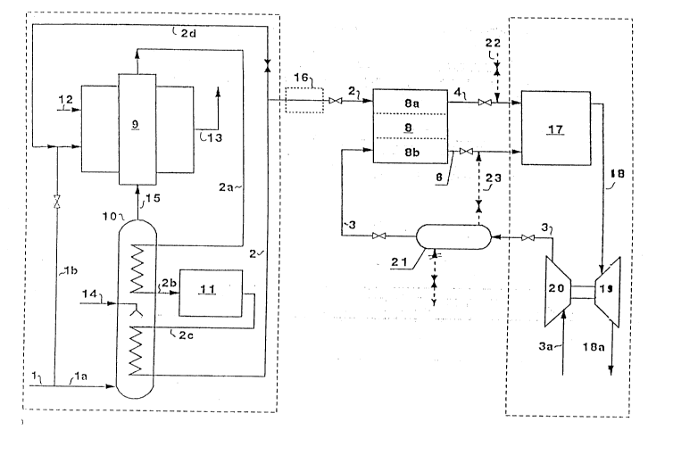
schematically illustrated in Figure 3. The installation
essentially consists of the systems H2-unit A, fuel cell system B
(with fuel cell 8), and compressed air generation unit C. In
the accompanying figure, the systems A and C are set off by
frames of dotted lines. Basically, any desired type of H2-feed
system can be used for the fuel cell 8. In the event that the
pressure of the H2-unit A is lower than the specified operating
pressure of the fuel cell 8, in one refinement of the invention
there is a H2-compressor 16 (shown in dotted lines) in the
H2-supply line 2 to the anode chamber 8a of the fuel cell 8.
The preferred embodiment is the one illustrated in Figure 3, in
which the H2- unit is designed as a steam reformer installation.
By means of a line, a current 1 of gaseous hydrocarbons such as
natural gas or biogas is introduced into the reformer
installation. A partial current la of these hydrocarbons
reaches a saturator 10, in which it is saturated with steam.
2065385
Preferably, a saturator 10 llke the one dlsclosed in
the present applicant's European Patent Application No.
0 320 440 published June 14, 1989 is used for this purpose.
In the lower half of this saturator 10, the hydrocarbon gas
introduced in countercurrent to a water current supplied by
means of the water feed line 14 and runs downward, e.g. over
dripping or trickllng bodies (e.g. Raschig rlngs), is brought
lnto contact with liquid water. In this lower portion, the
saturator is indirectly heated by the latent heat contained in
the product gas (H2-rich gas) produced. For this purpose, the
product gas ls transported vla the line 2c lnto a heat
exchanger located in the lower half of the saturator 10. The
steam required for the saturation of the gaseous hydrocarbon
is therefore not supplied from outside, but originates
directly in the saturator 10 itself. After saturation is
reached, the hydrocarbon/steam mixture is heated further in
the upper portion of the saturator 10, so that it can be
introduced into the reformer 9.
This additlonal heatlng again occurs indirectly with
the latent heat of the product gas current, which comes
directly from the reformer 9 via the line 2a, and once again
is placed in countercurrent to the hydrocarbon/steam mixture.
The product gas current leaves the heat exchanger located in
the upper portion of the saturator 10 via the line 2b, which
leads to a CO/H2-shift reactor 11. Of course, as is
frequently customary, the shift reactor 11 can also consist of
two or more units connected in series, with interposed heat
exchangers to cool the product gas. In the shift reactor 11,
the H2-content of the product gas is increased in an
-- 10 --
20337-405
exothermal reaction, and the CO concentratlon is
correspondingly reduced. The temperature increase ln the
product gas which occurs in the shift reactor 11 promotes the
generatlon of the hydrocarbon/steam mlxture ln the lower
portion of the saturator.
- lOa -
20337-405
" 2065385
The hydrocarbon/steam mixture brought to the preheating
temperature travels via the line 15 out of the saturator 10 into
the reaction chamber of the reformer 9, which is preferably
heated indirectly, but which can also be heated directly. For
this purpose, for example, a partial current lb of the supplied
gas current 1 is burned in the combustion chamber of the reformer
9, with the addition of a combustion air current 12. This
combustion preferably takes place under atmospheric conditions,
so that no compressed air feed i6 necessary for the purpose. The
exhaust gas current from the combustion chamber is designated 13,
and can be used, for example, to preheat the water 14 being fed
into the saturator and/or to preheat the combustion air current
12. The possibility of the practically unpressurized combustion
contributes to the reduction of the manufacturing costs of the
reformer 9 and the other parts of the H2-unit A. In addition,
the steam reforming itself can take place practically
unpressurized or at low pressures (e.g. 1-5 bar), since if
necessary, the H2-compressor 16 can bring the current of the H2-
rich gas to the specified operating pressure of the fuel cell 8.
On the other hand, in the processes of the prior art, the steam
reforming must always take place at a relatively high pressure,
to achieve the operating pressure of the fuel cell B. The
maximum independence of the H2-unit A from the fuel cell system B
is thereby improved, i~ in the normal operating case, there is a
line 2d closed by a valve which allows the temporary introduction
of the H2-rich gas generated into the body (heating space?) of
the reformer 9. It is thereby easily possible to start up the
reformer from the cold state, or to temporarily operate it in a
standby mode with a m; n; m~lm production capacity, without having
to discharge the hydrogen produced from the fuel cell 8.
,~ 2065385
While the anode chamber 8a of the fuel cell 8 is supplied
with the H2-rich anode gas current via the line 2, the cathode
chamber 8b receives the required amount of gas containing 2 in
the form of compressed air via the line 3. In the illustrated
embodiment, there is preferably a compressed air reservoir
(buffer?) 21 included in the compressed air line 3, which is
equipped with a pressure relief valve, and temporarily stores
(buffers?) the compressed air compressed in a compressor 20, so
that compressed air can be available even if the compressor 20
is not working, or is not working at sufficient capacity, for
any reason. The compressor 20, which is preferably designed as
a turbo compressor and can also have several stages, takes in
the fresh air via the line 3a, and is connected for drive
purposes to a gas turbine 19. This gas turbine 19 is operated
with the combustion exhaust gases generated in a combustion
chamber 17, preferably by catalytic combustion. These
combustion exhaust gases are transported via the line 18 and,
following their decompression, are discharged once again via the
line 18a. In the combustion chamber 17, in normal operation,
the current of anode exhaust gas arriving via the lines 4 and 6
from the fuel cell 8 and containing a residual H2-concentration,
generally along with additional combustible components such as CO
and non-reformed hydrocarbons, and the current of cathode exhaust
gas, which has a residual oxygen content, are burned together.
In the event that the O2-concentration is not high enough
for complete combustion, in one refinement of the invention
compressed air can also be extracted from the compressed air
reservoir 21 via a line 23 which can be closed by a valve, and
transported into the combustion chamber 17. The invention makes
no provision for the use of the compressed air generated to
operate the H2-unit A.
~ 206~385
It is advantageous to also have a line 22 which can be
closed by a valve, and through which an additional combustible
gas (e.g. natural gas or biogas) can be introduced into the
combustion chamber 17, independently of the anode exhaust gas
current. In that manner, the operation of the combustion
chamber 17 and of the turbine/compressor system 19, 20 is also
possible, independently of the operation of the fuel cell 8.
Exhaust gas turbochargers like those used in automobile engines
are particularly suited for use in the compressed air generation
system C.
As a rule, the fuel cell 8 is operated so that the residual
concentration of H2, together with any other combustible
components of the anode exhaust gas which may be present, is
sufficient to release just enough heat during the combustion in
the combustion chamber 17 so that it is sufficient for the gas
turbine 19 to produce the required amount of compressed air.
The cooling of the fuel cell 8, which is not indicated in
detail in Figure 3, can be accomplished, for example, by means
of a closed circuit cooling, since the efficiency of the cooling
is not of primary importance with regard to the recovery of the
discharged heat (e.g. steam generation), since the preferential
system used as the H2-unit for H2-generation requires no process
steam at all introduced from the outside, but works with liquid
water in the saturator 10.
The requirements for the purity of this water are
significantly lower than the requirements for the cooling water
of the fuel cells in processes of the prior art, in which this
cooling water is converted directly into steam (open cooling
system), and for which the steam reforming must be used in the
context of the H2-generation. In closed cooling systems, the
temperature difference in the heat exchanger would not have been
sufficient for an efficient steam generation.
~ 206~385
In the present invention, the waste heat from the fuel cell
8, however, can be advantageously used to preheat the compressed
air current supplied through the line 3 to the fuel cell 8, or
the compressed air current, if any, fed to the combustion
chamber 17.
In the context of the invention, the fuel cell 8 can
basically be any type of fuel cell. Preferably however, types
AFC, SPFC and in particular PAFC are suitable, since they work
at relatively low temperatures (below 200C). High temperature
fuel cells such as MCFC and SOFC can also be used for the
execution of the invention, but they are less appropriate. The
operating pressure of the fuel cell should be kept in the range
of 1-10 bar, preferably in the range of 3-8 bar, since on the
one hand this makes possible a good yield in terms of
electricity generation, and on the other hand does not set any
particularly high requirements for the strength properties of
the mechanical components of the facility. In addition, the
pressure of the H2-unit can be lower, since according to the
invention, an H2-compressor can be interposed. Together with the
significantly simplified control and regulation technology as a
result of the fact that the principal aggregates of the unit can
be operated completely independently of one another, this
significantly reduces the total costs compared to conventional
facilities, which are extremely difficult to operate on account
of the high degree of integration of the principal aggregates.
As an additional important advantage, the invention
simultaneously achieves a significant improvement in terms of the
operating safety and availability of the facility. Not only is
it possible to easily control the startup of the entire facility,
during which the principal aggregates can be placed in operation
independently of the fuel cell system, but the reaction to load
fluctuations in the current consumption can also be easily
controlled, on account of the process separation of the principal
aggregates.
14
206~38~
The technical data of a 200 kW installation according to the
invention, which works with PAFC type fuel cells and corresponds
approximately to the installation diagram in Figure 3, are as
follows:
Feed Methane or biogas
Rated electrical power 180 kW
Thermal power 210 kW
Guaranteed electrical efficiency 40% (lower calorific
value)
Operating range 40% - 100%
Load change from 40% to 100% in 10 minutes
Natural gas consumption 3~7,000 kcal/h
The installation according to the invention is characterized
by a compact construction which occupies little space:
Steam reformer installation 6.0 x 2.5 x 5.0 m
Fuel cell 2.5 x 2.5 x 3.0 m
Turbocompressor 2.5 x 2.5 x 1.0 m