Note: Descriptions are shown in the official language in which they were submitted.
2ss~~~~
-WO 91/02394 ' 1 ' pCT/AU90/00339
TITLE: PRODUCING ELECTBOSUSPENSIONS
TECHNICAL FIELD .
This invention relates to improvements in apparatus
use3 to produce electrosuspensions of particulate matter
such as powders.
HACFCGROUhD APT
Electrosuspension, also known as electrodispersion,
is a technique for suspending fine particulate matter
witrin closed oz open containers and is usually produced
by applying high DC-potential to appropriately
Configured stationary electrodes fixed within a
dispersing chamber. The suspension effect is produced
by the interaction between the applied electric field
and the particles. The suspensions are typically in the
form of t dust-cloud which partially fills the container
above a static powder bed. Concentration of the cloud
may be adjusted by raising or lowering, as required, the
voltage that is applied to the electrodes. A typical
hut not exclusive electrode configuration is one where
ST0 L0tb~9Z SzlSltlf~ NOlSI~HS ZZ ~b't E6iZ0/S0
~06~399
WO 91/02394 ' 2 - PCT/AU90/00339
an electrode is embedded within the static powder bed,
while the other is positioned some 20-30 mm above the
autLac:C UZ LtlC pvwaer. wltnougn tnere are a number of
possible polarity combinations which can be used, it is
often the case that the embedded electrode is at earth
potential. While the applied voltage necessary to cause
suspensions is determined by factors such as the
relative spacing of the electrodes, the weight, size and
shape of particles, it is mostly well above l0 kV~and
can be as high as 30-40 kV. Particle sizes are
typically in the range of from a few microns to several
hundred microns.
Developments in the art of electrosuspensions have
been reported in the J. of Appl.Phys., 1980, 5.1 (10
5215-5222 and 5223-5227, and in the J. of Appl.Phys.,
1964 ;~, (11) 4088-9D94. Examples of applications of
these developments are also given in the United Kingdom
patents 2074610B and 2143999.
Prior art electrosuspension apparatus have
sufferred several inherent disadvantages:
Firstly, particles easily polarized by the electric
field, such as contained Dy many crystalline dielectrics
(e. g.: KC1. NaCl. sugar, ascorbic acid, nicotinamid),
tend to align themselves with the field and With each
other, forming chains, filaments or needles in the
process. There is a tendency for these formations to
attach themselves to one of the electrodes and act as
9TE L0Tb~9~ Szl~ld~1 NO1S13HS AT:bj C6iZ0iSE
~0~~~99
= WO 9I/02394 - 3 ' PCT/A U90/OQ339
field-concentrators, giving rise to intermittent and
later continuous ionization of air within the dispersing
space. As ionized air is electrically conducting, this
mechanism can collapse the high voltage field, resulting
in the sharp reduction of the suspended cloud. The
formation of filaments can be especially prevalent in
case of fibrous dust, such as asbestos and cellulose,
and it is often the case that these type of powders form
solid bridges eatendinp between the electrodes, while
voltage is applied.
Additionally, in applications which involve the
treatment or use of the suspended dust, (such as the
vapour coating of particles), it is often necessary to
removQ the suspension from within the electrode space.
While removal can sometimes be effected by a
cress-airstream through the system, this is not always
viable. Removal techniques based on the tendency of
particles to 'shoot past' the upper electrode, being
propelled by their own upward momentum have not
generally succeeded, as the fixed upper electrode acts
as a physical barrier to the particles. This difficulty
has been addressed by adapting electrode design, for
example, by using a wiremesh type configuration.
However, the tendency of the particles to eventually
block up openings can not be easily eliminated and is
particularly prevalent with dielectric dust. A factor
further limiting the amount and concentration of dust
LTB L0Tb~9~ S~1~J~1 NO1S13H5 6~:bt 2.620iS0
.lu n. '1 i
CA 02065399 1997-08-26 , ~G-~/~VO,D~OD 3'39
- 4 -
AMENDED
which can emerge through the electrode region is the
reverse charging of particles by physical contact with
the electrode, effectively reversing the charge and
therefore the direction of force which the particles
experience.
Yet another difficulty exists in relation to the
electrosuspension of particles having a size of a few
microns. Particles of this size are often referred to
as micronised particles and as used herein this term
refers to particles having a size of less then 30y~m.
Hitherto, it has not been possible to effectively
generate an electrosuspension of many types of
micronised powders.
This has placed severe limitations on the practical
use of the electrosuspension process in areas such as
the pharmaceutical powders industry, in paint-pigments
manufacture and handling, in areas of medical technology
and the like where often ultrafine powders must be used
with particle sizes in the range of 2-5 um or less.
DISCLOSURE OF THE INVENTION
It is an object of this invention to provide an
apparatus for producing an electrosuspension of
particles which will overcome or at least ameliorate one
or more of the above disadvantages.
Accordingly, in one aspect this invention consists
in an apparatus for producing an electrosuspension of
particles comprising a container to receive a bed of
..~...~~...-_.."...r,
~,~~ ~e'~ >j :~ ~,~. -..
~~Gi~~ ~~a~~ ~ <n v'?~a.i:~..n~9'
y.~.._..a......~.~ca
c~,~ ~ r v
CA 02065399 1997-08-26
?Li ~AU 90~~0 3'~~
- 5 -
AMENDED
said particles, at least two electrodes disposed within
said container for the generation of an electric field
to establish said electrosuspension above the bed, at
least one of said electrodes being mounted for high
speed rotation by associated drive means.
In a second aspect this invention consists in an
apparatus for producing an electrosuspension of
micronised particles comprising a container to receive
said particles, at least two electrodes disposed within
said container for the generation of an electric field
to establish said electrosuspension, a first of said
electrodes, in use, being disposed in contact with a bed
of said particles and a second of said electrodes being
spaced apart from said bed of particulate material, and
electric field concentrating means connected with said
second electrode to generate ions and irradiate the
surface of said bed of particles with ions of opposite
polarity to said first electrode.
In a third aspect this invention provides a method
fog producing a electrosuspension of micronised
particles comprising the steps of applying an electric
field transversly across a bed of said particles and a
region adjacent one surface thereof and irradiating said
one surface with ions of a polarity naturally propelled
toward said one surface by the electric field such that
secondary ionisation of air or gases within the particle
bed occurs sufficient to allow electrosuspension of the
r ".,,. ~ , ~ ~. ..: i= . .~ a
," r : ~;, ..~. i' ~ a
.... -~.w- - .._
~Jvn°~L
CA 02065399 1997-08-26
PGT (A V °X~I ba3~~
- 6 -
- AMENDED
particles.
Preferably, in the second aspect of the invention
the second electrode is also mounted for high speed
rotation by associated drive means. The concentrating
means preferably comprise thin wires attached to the
second electrode.
It is further preferred that the electrode mounted
for high speed rotation or "rotatable electrode" has an
open configuration to allow the particles to pass
through or across the electrode. In this respect, the
electrode can, for example, be of "mesh-like"
construction or have a drum like configuration as shown
in the accompanying drawings. Alternatively, the
electrode can be similar to a fan comprising blades
across which the particles may pass.
Preferably the rotatable electrodes) is/are
capable of angular speeds in excess of 1500 rpm while
being electrically charged to normal dispersing
potential, usually in the range 10 kV to 40 kV.
-- The rotatable electrodes) can be charged to either
negative or positive polarity, or be operated at earth
potential. Pulsed charging and superimposed AC on DC
charging and/or operating the electrodes in a purely AC
mode are also possible.
Preferably at least one rotatable electrode is
positioned above the surface of a static bed of
particles to be suspended, with sufficient clearance to
~'°~_.,.,_.........-..._._...._,_..~,~..a...
~3' ~~ ~ a iA . ': d :; :"
1
5~~n°~~
CA 02065399 1997-08-26
P~~~ Jgd ~Oo'~3°.5
- 6a -
- AMENDED
prevent direct electrical contact with the bed. In one
embodiment the rotational axis is substantially parallel
to the bed surface but it will be appreciated that many
246~39~
~ ~'~WO 91J02394 - ~ ' PCf/AU90100339
other configurations are possible.
Where more than one rotatable electrode is
utilised, these can be operated at different rotational
speeds and directions or in any suitable combination
thereof.
The rotating electrode can be constructed from nny
suitable known material or combination of materials for
eaample, dielectric materials in combination with
metals. In some applications~the materials are selected
to ensure a smooth operation in a dusty environment.
The electrosuspension apparatus according to the
invention has been found to provide the following
advantages:
i) The provision of a charged region o~ space,
through which particles are substantially free
to move:
ii) A substantial reduction in the tendency of
powders to form filaments during dispersion;
iii) A substantial reduction in ionization
discharge resulting from the attachment of
particles to the electrodes;
iv) The production of aerodynamic forces to propel
particles through the rotor:
v) The reduction of inter-electrode spacing:
In the case of micronised particles the apparatus
of the second aspect of this invention has been found to
allow the effective electrosuspension of particles not
W0 L0Ib~5~ S~i31ti~1 N~1S'1SHS ~~b'I Z62AiS0
2~6~~~9
WO 91/02394 ' 8 ' PCT/ALs90/00319
capable of electrosuspension in prior art devices. The
inability of prior art devices to successfully create
electrosuspensions of many miczonised particles is
thought to be a consequence of the high electrical
resistivity such particles exhibit in bulk.
Where the apparatus consists of a~ststionary
electrode embedde8 in the bed of particulate material.
the usual mode of charging the particles is by
electronic conduction. The high electrical resistivity
due to contact resistances between the particles of
micronised powders prevents or hinders the charging of
particles by electron-conduction through the bed in
apparatus used to generate suspensions. Under normal
dispersing (electrosuspension) conditions, the
application of voltage to the electrodes results in the
charging of surface particles by conduction of electrons
from the embedded electrode to the surface of the bed,
via the individual particle-contacts throughout the
bed. It is known that beds of particles consisting of
small dielectric particles exhibit a volume. resistance
increasingly determined by the number of contacts,
rather than the overall electrical resistance of the
particles themselves, especially as particles get
smaller. It is also known that contact resistance
between dielectric surfaces is non-ohmic, i.e. Current
is not in proportion to the applied voltage. This is
further illustrated by the non-ohrnic resistance of bulk
~2~ L0W~9~ SbOlNf~ NO1S~=HS ~Z ~ bT ~6iZ0iS0
29~~399
W'O 91/OZ39d ' 9 ' PCT/A 090/00339
powder, so that electrical resistance depends on the
applied voltage, rather than being an independent
constant determined only by the electrical properties of
the material. With decreasing sizes the number of
inter-particle contacts are known to multiply, which can
lead to volume resistivities well in e=cess of 1012
Ohm-crn for ultra-fine powder. thereby preventing the
continuous and regular passage of charge needed to
maintain a suspension.
It should be noted that there are some micronised
powders which do not ezhibit the above properties. For
eaas~Fle a sample of free-running nickel powder,
consisting of 3-5 dun spherical particles, Was found to
disperse quits freely, while other more cohesive metal
powders show some reduced activity. Exceptions also
ezist among ultrafine non-metal powders, such as
micrenised pyridoain hydrochloride, which does show some
dispersion after appropriate surface-treatment of the
powder, though particles tend to disperse as 30 um
agglomerates rather than individuals. Theoretically,
the ability to disperse a few ultrafine powders is
probably due to a presently little understood mechanism
which regulates the contact resistance between particles.
The essence of the second aspect of this invention
is to circumvent the conduction charging of particles
(made difficult by the high electrical resistance of a
powder bed) by providing an alternative or additional
~~0 Z0TbZ9~ SbSld~l NO1S~SHS bZ ~bt 2b20~S0
~o~~~oo
WO 9I/0239.~ - 10 - PCf/AL~9~/U03~
mechanism that relies upon the secondary phenomenon of
back-ionization.
Back-ionization is an electrostatic effect rarely
encountered in high voltage practice other than
electrostatic precipitation. Where it represents an
unwanted side effect urhich reduces the efficiency of the
precipitation grocess and is one to be eliminated as
much as possible.
Thus, according to the second aspect of this
invention, the particles may be charged by the secondary
ionization of air or gases within the particle bed.
which secondary ionization occurs in response to
spraying the bed with primary ions preferably produced
by a corona-discharge within the electrosuspension
container.
BRiE~' DESCRIPTION OF THE DRAWINGS
The invention will now be described, by way of
example only, with reference to the accompanying
drawings in which:
Figure 1 is a schematic illustration of the
apparatus according to the first aspect of the invention;
Figure 2 is a schematic illustration of apparatus
similar to Fiqure 1 which includes the second aspect of
this invention.
MDDES F9R CARR'~ING OUT THE INVENTION '
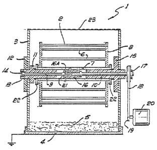
Referring to Figure 1 there is shown an apparatus 1
for the electrosuspension of the particles which
b~0 L0Tbd92 SbSlti~1 NO1S~SHS S~~b'L Z6~d0iS0
206~~~0
' .~w0 91/OZ39a - 11 - . PCf/AU90/00339
includes an electrode 2 mounted for rotation within an
insulating container 3. A second electrode 9 is fitted
within the bottom of container 3 below a bed of
particulate material 5. The rotatable electrode 2
comprises a drum like rotor formed by circumferentially
spaced conductors 6 eztending substantially parallel to
and equaily distant from a hollow cylindrical tube 7.
The conductors 6 are joined to respective disk shaped
end portions 8 secured to the tube 7. The rotatable
electrode 2 is mounted by shafts 9 and 10 above the
particle or powder bed 5. Shaft 9 is disposed within a
teflon bearing I1 about which the rotor rotates. The
assembly comprising the shaft 9 and bearing 11 is fined
to a wall of container 3 by'an insulating retaining ring
12. The outer end of the shaft 9 is surrounded by
further insulation 13 to form an electrical Contact 14.
Shaft 10 is rotatably mounted within a further teflon
bearing 15 which is fi:ed to the side of container 3.
One end of shaft 10 is fined by means of an insulating
bush 16 to the cylindrical centre tube 7 of electrode
2. The other end of shaft 10 protrudes from container 3
and is fitted With a pulley 17. A belt 18 eztendS
between pulley 17 and a like pulley 19 on an electric
motor 20. In this Way, the electric motor Cari be
energised to rotate electrode 2. Electrical connection
between shaft 9 and the electrode 2 is maintained by
means of a steel ball 21 disposed in a recess within a
fee L0'Ib~S~ S?JSltl~1 NO1S~SHS S~ ~bT 2biZ0iS0
206399
WO 91 /02394 - 12 - PCT/All90/OQ33a
conducting portion 16A of bush 16. The ball 21
effectively provides a bearing between the stationary
end of shaft 9 and the bush portion 16A whilst the
insulating remainder of bush I6 prevents electrical
contact with shaft 10.
Dust sleeves 22 are fitted between the teflon
bearings I1, 15 and the respective ends 8 of electrode 2
to ezclude dust from the bearing surfaces.
In use, an electrical potentional is applied
between electrodes 2 and 4 and electrode 2 is rotated by
means of a current supplied to electric motor 24. This
creates an electric field in the region between the two
electrodes and results in the generation of an
electrosuspension of the particles. Because the
electrode 2 has an open configuration and due to the
turbulence cause8 by the rotation the electrosuspension
rises into the area above the electrode 2. From this
area the suspension can be readily removed by any
suitable known means. In the embodiment shown in Figure
1 container 3 has an open top fitted with a grid 23 to
provide for the filtering out of any coarse particles in
the electroauspension.
Referring to Figure 2 the arrangement illustrated
is generally the same as that described in relation to
Figure 1 above. For ease of understanding the same
_.c..~,.r... w.Lrwnr'le l~yjQ flGOn L1c_o_f~ tQ 3tlPntify
corresponding parts. In the Figure 2 arrangement a
9~E Z0TbZ9~ SaSltit~ NO1SISHS 9~~bt ?.6i~0iS0
2a6~~9~
~"'~O 9i/02394 - I3 - PCTIAL'90/00339
number of thin wires 24 are sycnmetricaliy positioned
about the periphery of electrode 2. Each wire 24
extends arcuately between the ends 8 of the electrode
and is weighted at its centre by means of a porcelain
bead 25. Additionally, the Figure 2 arrangement
includes a solid semi-conducting layer 26 covering
electrode 4.
The apparatus of Figure Z is particularly designed
for use with micranised particles which do not under
normal circumstances readily form an electrodispersion.
The operation of the device is generally similar as that
described above in that a potential is applied between
the electrodes and electrode 2 is rotated at a
relatively high speed by motor 20. The thin wires 29
attached to electrode 2 extend outwardly under the
action of centrifugal force and act as field
concentrators to produce a corona-discharge. This
results in an ionization of the air or other gas within
the container 3. Such corona-ionization is en effect
well known to those familiar with electrostatics and has
wide application in areas such as Electrostatic
Precipitation, where it is usually produced by a static
pair of electrodes using a point/plane or thin
wire/plane construction. With the present invention,
the ions are generated by the rapidly rotating positive
electrode 2. The resulting negative ~on5 are
immediately re-absorbed by the electrode. whilst
L,de L~W~9~ S~J~1J~1 NO1S1~HS l~:bW6i~0iS0
2~6~~~~
~ WO 9110239a - 19 - PC?/AL'90/Q0319
positive ions are sprayed onto the surface of the
pazticles 5, as a result o~ electrostatic attraction and
by the aerodynamic forces to which the electrode 2 gives
rise. Due to the high electrical resistance of the bed
5, these ions do not immediately dissipate but form a
positive charge-Layer on the surface ef the bed 5. the
underside of which is at the opposite potential, caused
by electzical contact with the lower electrode 4.26. In
turn, this gives rise to a high potential drop across
the particle Dea 5 causing zne ionization or air wzcnin~
the interstitial space between particles. This is
usually termed back-ionization and is a known secondary
effect by which ions of both signs are produced, one
being rapidly absorbed by the electrode, while the other
is driven upward through the particles and is absorbed
by the particles which thus become charged. L3sinq the
above proposed polarity configuration, these are
negative ions, i.e., electrons, resulting in the
immediate dispersion of the particles. which forms a
cloud of suspended particles above the bed 5.
An optional feature of the invention is the
prevision of means for adjusting the electrical
potential across the particle bed. This may be achieved
by adjustable vertical positioning of the upper
electrode, Which allows bed-thickness to be varied as
required as schematically illustrated in FiQ. 2 at 27.
This can also be achieved using an appropriate '
B~e L0IbZ9~ SbOldf~ NO1S'i.OHS 8~~bW620iS0
246~34~
="i'O 91 /0239d - 15 - PCT/AU90/00339
semi-conductor substrate for the bed, as illustrated at
26 in Fig.2 is provided, through which electrical
contact can be made with the lower electrode. A
miss-match of resistances between the interelectrode
space and the layer of particles can result in either of
the following two unwanted conditions: (I) insufficient
potential difference across the bed to give rise to
secondary ionization and i2) the potential difference
across the bed is too high relative to the
interelectrode voltage, so that when the potential
across the bed is suddenly added to the former as
charges begin to flow, then the combined potential
ezceeds the sparking volta0e for the system. causing
electrical sparks and discharges in place of the
continuous secondary ionization which is required.
8y Way of illustration of the invention the
following experiment has been performed. In an
apparatus as described with reference t0 Figuze 1 an
electrosuspension was generated using 100gm Of dry ICCl
(containing 0.05% free flow agent additive) by applying
25,000 volts to the rotationable electrode positioned
3omm above the powder bed. The rotor was 45mm diameter
and 6omm long. The density of the electrosuspension was
monitored by using a transmitted He-Ne Laser beam and~by
measuring the attenuation of the beam through the Clotld
With a Laser power Meter. Operation of the rotor 8t
lao0 r.p.m. caused a drop of over 40% in the transmitted
6d6 L01 b~9Z Szl31ti~1 NO1S13HS 6~ : bZ cbi~0/S0
~Q~~399
WO 91/02394 - 16 - PCT/AL9010Q3Z9
beam intensity from the initial 2.8 mw measured with the
rotor stationary. This indicates a considerable
increase in the density of the suspension.
INDUS RIAL APPLICABILITY
One a:ample for using the above invention is in
producing coated pharmaceutical powders for Controlling
the release rate of the active ingredient through a
semi-permeanla memarane covering each parzieir. iim
electrosuspension of particles is well suited for the
continuous production of such surface-treated powders.
as the particles are separate from each other arid iri
continuous agitation while in dispersion. thus allowing
the coating to be applied by a suitable technique, e.g:
by spraying them With fast-drying aerosol. The main
difficulty, however, is to produce satisfactory
eiectrasuspensions, since many pharmaceutical substances
contain easily polarized crystals whicr. tend to form
filaments under the action of the electric field.
Often, these substances are also quite hygroscopic which
further exacerbates the problem, resulting in extremely
poor and uneven dispersions that usually deCreaSB With
time, until the process stops. By using the apparatus
of the present invention, this problem has been sharply
reduced and a dense cloud of suspended substance can be
maintained, sufficient for most electrosuspension
coating applications.
Another example for applying the present invention
C~0 L~Ib~9Z S~ISl'~f~ NO1S'13HS 0~:b1 2120iS6
~a~5~~~
17 - PCT/A U90/00339
' ~~WQ 91 /0239a
is in the area of dry paper-making. Paper is usually
formed by the process of floating individual paper
fibres (originating from treated wood-pulp) in large
vats of water and allowing the fibres to settle on a
suitable substrate, e.g: a moving wire-mesh strip, from
where the pager is removed and dried. In view of the
large quantities of water which must be handled
(typically 1/2 ton of water for~2kgs of paper), a
technique which would allow the dry separation end
floating of fibres is likely to have important economic
significance. The electrostatic suspension of cellulose
dust is one such possible technique, but due to the
earlier mentioned tendency of fibrous dust to form long
chains and filaments when subjected t a high voltage
field, cannot be used in practice. Hy using the
apparatus of the present invention, a suspension of
fibrous dust can be maintained as a result of the
mechanical disruption of the filament-forming process by
the rotatable electrode, thereby eliminating the problem
with adapting this technique to dry paper-making.
A further ezample for the use of the present
invention is in coating of solids. For instance, the
invention makes it possible to produce electrostatically
coated abrasive, such as belts. disks and paper to which
fine silicon carbide, emery, etc., is glued using
grit-sizes much finer than presently possible. It also
becomes possible to 'weld' ceramics to metal by
Ire L0Ib~5~ S~ISld~1 NO1S'1SHS 6~:b1 d6s~0iS0
~~~~~9~
05~2i92 14:35 SI-~LSTON WRTEF2S 262410'7 002
' WO 9I /OZ394 - 18 ' PCT/A L'90/00~:9
depositing ultra-fine ceramic dust on a heated metal
surface, which minimises the cooling of the surface by
large heat capacity grains, so that direct sintering Of
the grains may be achieved both to the metal surface and
to each other. The bonding of ceramics to metal is an
important technoiogicai problem occurring in modern
automotive engineering ns well as in aviation and the
space industry and has not yet been solved in an
economically viable manner.
Another eaample for the use of the invention is for
producing aerosols of ultrafine medically active
substances, such as salbutamol sulphate. pentamadin and
steroids, suitable for the treatment of various forms of
asthma, aids, etc., by directly inhaling them into the
lungs. Present inhalers of dry ultrafine powders in the
1-3 }:m size range typically based on compressed CFC
delivery of the dust, for which breathing must be
co-ordinated with the bursts of powder generated by the
device. In most cases. this is a difficult requirement,
especially for children. Devices which rely on a
suction generated when the patient inhales deeply are
also known. However, deep inhalation can be difficult
or impossible for an asthmatic and these devices are
therefore of limited use. It has been found, the
present invention has the capacity for overcoming the
problem, as demonstrated for salbutamol sulphate which
was dispersed from an apparatus, as shown in Figure Z,
20~~3~9
05i02i92 14:35 SHELSTON WRTERS 2624107 003
~-~'O 91/02394 - 19 - PCT/AEJ90/00339
producing a slowly rising cloud of ultrafine powder
which may be inhales: by breathing normally.
A further example for the use of this invention. i5
in making new surface-active catalysts, by Coating the
micronised catalyst onto the individual grains of an
'inert' carrier, such as a 30 dun alumina powder, to
which the micronised particles can stick due to natural
adhesion forces. The technique could be used to replace
-_ present less economical methods for manufacturing such
surface-active catalysts, where the active material is
spread over the carrier grains by precipitating them
from a liquid.