Note: Descriptions are shown in the official language in which they were submitted.
CA 02065453 2001-06-O1
-1-
WIPER CLEARING DEVICE
Background of the invention
Field of the Invention
This invention relates to a wiper blade cleaning system for cleaning debris
from window wiper blades in which the blades travel over discrete scraping
elements
in the form of projections or depressions formed in or added to the window to
be
wiped by the wiper blade. The primary use of the present invention is for
windshield
wipers for vehicles used to wipe both the front windshield and the rear
window, but
the system may be used in other
WO 91/03978 PCT/L.!S90/04941
~'~(~~' ~ ~J~ _ 2
environments, as well. For purposes of illustration and
description only, this invention will be described with
reference to windshield wipers, without limiting other
uses of the invention.
Description of the Prior Art
The need for removing debris from wiper blades,
particularly wiper blades used in automobiles, trucks, and
other land, water and air vehicles, has long been
recognized. This necessity 'is brought on by the
accumulation of debris such as dirt, oil, insects, leaves,
ice, snow, etc. on windshield wipers. Accordingly,
numerous devices for cleaning windshield wipers and
keeping wipers free from such debris have been proposed.
For example, U.S. Patent No. 2,974,340 discloses
an attachment for cleaning windshield wipers which
comprises a transparent strip which may be attached to a
windshield, the transparent strip having ribs thereon
which will scrape and clean the wiping edge of the
windshield wiper. Similarly, U.S. Patent No. 4,685,168
discloses a wiper blade cleaner which is a rectangular
strip made of transparent material which is either affixed
to or formed integrally with the windshield. The strip is
approximately the same size, i.e., length and width, of
the wiper blade itself and has a non-abrasive surface.
WO 91/03978 PCT/US90/04941
_ 3 _
U.S. Patent No. Re. 32,218 discloses a
windshield for automobiles having at least one scraping
edge in the path of a windshield wiper. The scraping
edge, extending for the length of the wiper blade, has
either an inverted U or an inverted V shape. The scraping
edge is fabricated as part of the manufacturing process of
the windshield. U.S. Patent 4,616,376 discloses a means
for cleaning a windshield wiper blade which is also built
directly into the windshield. The cleaning means of this
reference comprises a groove ground into the windshield,
wherein the bottom of the groove has ridges extending
longitudinally within the groove.
Another example of a device for cleaning
windshield wipers is U:S. Patent No. 3,908,222 which
discloses a windshield wiper blade cleaner which comprises
a plurality of spaced, independent units~which are
permanently mounted on the windshield. The units are
formed in a single row and have a diamond shape wherein
opposite points of the diamond are pointed in the
direction of oscillation of the wiper blade.
However, none of these known devices have proven
to be entirely successful in cleaning windshield wipers so
that all of the debris, snow, ice, etc. accumulated on the
wipers are effectively removed from the entire length of
the wiper each time the wiper passes thereover without
WO 91/03978 PCT/US90/04941
causing undue wear to the wipers or scarring of the
windshield. Moreover, the debris, ice, snow, etc. cleaned
from the wipers may accumulate on the device, thereby
adversely affecting its cleaning capabilities.
Accordingly, an objective of the present
invention is to provide a device for clearing all types of
debris from windshield wipers which, if not cleaned from
the wiper, would hamper the clearing efficiency of the
wiper blade. A further objective of the present invention
is to clean the entire wiping edge of the blade with each
pass of the wiper over the clearing device. An even
further objective of the present invention is to provide a
configuration of the clearing device which will not allow
the buildup of debris, snow, ice, etc. on the cleaning
device itself.
Clearing devices of the present invention which
are adhesively attached to the windshield also have
advantages of being applicable to glass or other smooth
surfaces. They are durable and can be easily renewed and
are inexpensive and easy to install.
Bummarp of the Invention
The objectives discussed above are obtained by
the present wiper clearing device for removing debris from
the surface of a window wiper which comprises a plurality
WO 91/03978 PCT/US90/04941
~('~5~53 _ 5 _ ... .;
of discrete scraping elements on the window, the scraping
elements being arranged in two or more groups disposed in
a path in which the wiper travels to wipe the window. The
groups should extend for a distance corresponding to the
length of the wiper. The scraping elements of one group
should be at least partly aligned with the spaces between
the scraping elements of the adjacent group.
Hrief Description of the Drawings
For the purpose of illustrating the invention,
there is shown in the drawings forms which are presently
preferred: it being understood, however, that this
invention is not limited to the precise arrangements and
instrumentalities shown.
Fig. 1 is an illustration of a prior art
windshield/windshield wiper system.
Fig. 2 is a view of the present device formed
integrally with a windshield.
Fig. 3 is a view of the device of Fig. 2 located
in a parked position below the arcuate sweep pattern of
the wipers when the wipers are operating, but above the
windshield wipers when the wipers are in the off position.
WO 91/03978 PCT/US90/04941
~r~~Jv~~ - S . -.
Fig. 4 is an enlarged illustration of the
present device containing groups of elongated projections,
wherein the projections are adhesively attachable to a '
windshield.
Fig. 5 is an enlarged illustration of the
present device comprising elongated depressions, wherein
the device comprises a planar base member.
Fig. 6 is an enlarged view of the present device
comprising elongated projections, wherein the device
comprises a planar base member.
Fig. 7 is an elevational view of the present
device looking along the bottom edge of the embodiment
illustrated in Fig. 6.
Fig. 8 is an illustration of the present device
wherein the scraping elements are circular and located in
a parked position below the arcuate sweep pattern of the
wipers when the wipers are operating, but above the wipers
when the wipers are in the off position.
Fig. 9 is a cross sectional view of the device
depicted in Fig. 8, taken along lines 9-9 of Fig. 8,
Fig. 10 is an enlarged view of the present
device wherein the scraping elements are raised, circular
projections which are adhesively attachable to a
windshield.
WO 91/03978 PCT/US90/04941
~~~~~~ 73
Detailed Description of the preferred Embodiments
The present invention will be described with
reference to the drawings, wherein like numerals indicate
like elements throughout the several views.
Fig. 1 illustrates a typical vehicle windshield
with which the present invention may be used.
Associated with the windshield is a pair of windshield
wiper arms 12 carrying windshield wipers 14, including the
usual rubber wiper blades. As used herein, the term
l0 "wiper'' refers to the wiper blades which contact the
windshield, window or other surface which is wiped by the
wiper. The wipers 14 are illustrated in Fig. 1 as being
in a parked position below the typical arcuate sweep
pattern 16 of the wipers when they are operating to wipe
the windshield.
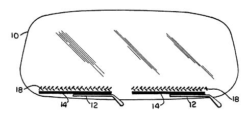
Fig. 2 illustrates a preferred placement on a
windshield of one embodiment of the wiper clearing device
of the present invention in the form of two scraping
arrays 18, each of which represents a clearing device of
the present invention. The scraping arrays 18 are
comprised of a plurality of discrete scraping elements 20
arranged in two or more .groups, two groups 22 and 24 being
shown in Fig. 2 for purposes of illustration.
WO 91/03978 PCT/LJS90/04941
,",,
rG~~Jv~ 8
The discrete scraping elements 20 of the present
clearing device may be of any shape which will be
effective in cleaning the wiping edge of a windshield
wiper blade 12. To be effective, the scraping elements 20
should have edges which cause a scraping or wiping action,
together with a flexing action, on the wiper as the wipers
14 pass over and contact the scraping elements 20. The
discrete scraping elements 20 are spaced from each other
by a distance such that dirt and other material can be
scraped from substantially the entire. length of each wiper
14 by each array 18, and such that the material so removed
can channel between and be easily removed from the arrays
18. The plurality of scraping elements 20 forming the
scraping arrays 18 are arranged in groups 22 and 24
wherein the scraping elements of one group, say grnup 22,
are at least partly aligned with the spaces between the
discrete scraping elements 20 of the adjacent group(s),
say group 24.
It is preferred that the scraping arrays 18
forming the wiper clearing device of the present invention
be positioned on the windshield 10 at a location slightly
above the wipers 14 when the wipers are in the off
position. This preferred embodiment is illustrated in
Figs. 3 and 8. In this preferred parked position, the
scraping arrays 18 are below the arcuate sweep pattern 16
WO 91/03978 PCT/L,'S90/04941
2t~~u~~~
g
of the wipers. Further in this preferred parked position,
the wipers 14 will pass over the arrays 18 when the wipers
are turned both on and off, to clean the wipers prior to
and at the end of each wiping session. Moreover, such an
embodiment allows the clearing device to be placed in a
location on the windshield 10 which will not block the
field of view of the driver and thereby not hamper the
driver's vision. The device will also filter the sun's
harmful radiation when placed in such a location.
Alternatively, the wiper clearing device of the
present invention may be located on the windshield at any
location which is within the path of the movement of a
wiper, such as within the arcuate sweep pattern 16 of the
wipers. In this embodiment, the discrete scraping
elements 20 may be transparent, since they will be in a
position on the windshield 10 which will allow the wipers
14 to pass over the arrays 18 of the clearing device as
the wipers move over the windshield during the normal
wiping action.
~ In one preferred embodiment of the present
invention, the scraping elements are arranged on a first
scraping element assembly 26, illustrated in Fig. 4. The
assembly 26 comprises a backing sheet 28 to which
discrete, spaced scraping elements 30, 32 are releasably
attached. The backing sheet 28 is coated with a release
WO 91 /03978 PC1'/US90/04941
i~[:~~~ - 10 -
material, such as silicone, to release the elongated
scraping elements 30, 32 from the sheet to which they are
adhesively, but removably, attached. Another release
sheet 29 removably covers the opposite surface of the
scraping elements 30, 32, which surface is coated with an
adhesive to attach the elongated scraping elements to the
windshield 10 or other object to be wiped.
In use, the release sheet 29 is removed from the
assembly 26, exposing the adhesive coated scraping
elements 30, 32. The scraping elements are then applied
to the windshield by placing the assembly 26 in the
desired position on the windshield or other object to be
cleaned with the exposed adhesive surfaces of the scraping
elements 30, 32 in contact with the windshield which
should be clean to enhance adhesion.
once the scraping elements 30, 32 are firmly
adhesively attached to the windshield, the backing sheet
28 may be removed from the scraping elements. This leaves
the scraping elements 30, 32~attached to and extending
from the surface of the windshield. Thus, the scraping
elements 30, 32 are elongated projections extending from
the windshield.
The elongated projections 30, 32 are arranged in
at least two groups 22 and 24. Each of the groups 22 and
24 comprises a series of generally parallel elongated
WO 91/03978 PCf/US90/04941
11 -
2('~u~53
projections 30 and 32, respectively. The projections 30
of one of the groups (e.g., 22) are spaced and arranged in
a manner so that they are oriented generally perpendicular
to the projections 32 of the other group (e. g., 24). Such
an arrangement provides for the effective clearing and
cleaning of the wiper while simultaneously allowing for
drainage and resisting the accumulation of debris, snow,
ice, etc. which may form on the edge of the wiper blade.
Although the scraping elements 30, 32 may be
l0 adhesively attached to the windshield as described with
respect to Fig. 4, the scraping elements 20 of the present
invention can be integrally fonaed in the windshield
during its manufacture as illustrated in Figs. 2 and 3.
The integrally formed scraping elements may be of the same
elongated shape and in the same alignment and orientation
as described above with reference to Fig. 4.
Alternatively, in another preferred embodiment,
the scraping elements 20 may be in the form of depressions
in a second scraping element assembly 34, as illustrated
in Fig. 5 The assembly 34 comprises a backing sheet 36
which is adhesively, but removably, attached to a scraper
element sheet 38. Formed in the scraper element sheet 38
are a plurality of elongated depressions 40, 42 arranged
in at least two groups 22 and 24, respectively. Each of
the groups 22 and 24 and depressions 40 and 42 comprises a
2C;~~~a3 PCf/US90/04941
WO 91 /03978
- 12 - ,"
series of generally parallel elongated depressions. The
depressions 40 of one of the groups (e. g., 22) are spaced
and arranged in such a manner that they are generally
perpendicular to the depressions 42 of the other group
(e.g:, 24). In this embodiment, the depressions 40, 42
trap the debris from the wiper 14, thereby removing it.
The perpendicular arrangement of the depressions 40 and
42, like the similar arrangement of projections 30, 32
promotes drainage and resists the accumulation of debris.
In use, the assembly 34 is applied to a clean
windshield 10 or other clean surface to be wiped, by a
simple installation process. The backing sheet 36 is
removed,~exposing the adhesive coated on the surface of
the scraper element sheet 38 to be attached to the
windshield. The assembly is then carefully positioned in
the desired location and attached to the windshield by
pressing the assembly 34 with the adhesive surface against
the windshield.
The assembly 34, once applied to the windshield,
also provides two additional scraping edges 39'and 41,
corresponding to the top and bottom edges, respectively,
of the assembly as illustrated in Fig. 5. When the wiper
travels over the assembly 34, debris will thereby be
WO 91/03978 PCT/US90/04941
13 _ 2('~J~'J~
scraped and removed from the wiper by the edges of the
depressions 40 and 42 and by the edges 39 and 41 of the
assembly.
As with the scraping elements in the form of
elongated projections 30, 32 as discussed above, the
elongated depressions 40, 42 could be formed integrally
within the windshield 10 during manufacture of the
windshield. Alternatively, the depressions 40, 42 could
be formed directly in the windshield after manufacture by
etching or otherwise removing glass from the outer surface
of the windshield by techniques well known to those
skilled in the art.
Another preferred embodiment of the present
invention is illustrated in Figs. 6 and 7 with respect to
a third scraping element assembly 44. The assembly 44
comprises a backing sheet 46 releasably covering an
adhesive coating 47 applied to a scraper element sheet 48.
The scraper element sheet 48 has top and bottom edges 49,
51 which act as scraping edges for a wiper. When the
assembly is attached to a windshield or other surface to
be wiped.
Extending from.one surface of the scraping
element sheet 48 are a plurality of discrete scraping
elements in the form of elongated projections 50, 52
arranged in two groups 22, 24, respectively. The
WO 91/03978 PCT/US90/04941
~~~3%. ~ - 14 -
. , .'"'"
arrangement and orientation of the elongated projections
50, 52 on the assembly 44 are preferably substantially the
same as set forth above with respect to the projections
30, 32 on~the assembly 26 illustrated in Fig. 4 for
substantially the same reasons. However, the projections
could take other forms and have different spacings so long
as there are scraping elements 20 formed in at least two
groups 22, 24, such that the scraping elements of one
group are aligned with the spaces between the scraping
elements of the adjacent group(s).
The assembly 44 is applied to a windshield by
removing backing sheet 46 to expose the adhesive coating
47. The assembly is then positioned in the desired
location on the windshield and the adhesive coating 47 is
pressed against the windshield, after the windshield has
beew cleaned.
Another preferred embodiment of the present
invention is illustrated in Figs. 8, 9 and 10. In this
embodiment, the scraping elements 20 take the form of
raised, circular projections 54 extending from the outer
surface of the windshield and arranged in two or more
rows. Preferably, in this embodiment, the wiper clearing
device is grouped in at least four rows as illustrated in
Figs. 8, 9 and 10, the four rows being identified as 56,
58, 60 and 62. The raised, circular projections 54 are
W0 91 /03978 PCT/LJS90/04941
15 ~~~ ~J'
arranged generally in a staggered vertical alignment,
wherein the projections 54 of every other group,(e.g.; 56
and 60, 58 and 62) are generally vertically aligned.
When the scraping elements 20 of the present
invention take the form of raised circular projections 54,
the projections may have any appropriate diameter
sufficient to provide effective cleaning of a wiper 14.
However, it is preferred that the raised circular
projections 54 have a diameter of about 1.5 to about 4.5
mm, and more preferably, about 3.0 mm. Also, the raised
circular projections 54 may have any appropriate thickness
or height which is. sufficient to provide effective
cleaning of a windshield wiper blade 14. However, it is
preferred that the raised circular projections 54 have a
thickness in the range of about 0.15 mm to about 0.45 mm,
and more preferably about 0.3 mm. With each group or row,
the raised circular projections 54 preferably should have
a generally horizontal spacing in the range of about 6.0
to about 9.0 mm, and more preferably, about 7.5 mm. The
preferred center to center generally vertical spacing is
in the range of about 4.5 to about 7.5 mm, and more
preferably, about 6.0 mm.
The circular projection scraping elements 54 are
preferably applied by adhesive to the windshield 10, as
illustrated in Fig. 10, if they are not integrally formed
WO 91/03978 PCT/US90/04941
i~~~~~~3~ 16
with the windshield during its manufacture. The technique
for adhesive application is substantially the same as that
explained above with respect to the embodiment illustrated
in Fig. 4. Thus, the scraping elements 54 are adhesively,
but removably, attached to a backing sheet 64, and a
release sheet (not shown) removably covers the adhesive on
the opposite surface of the scraping elements. When the
release sheet is removed, the adhesive is exposed. The
circular projections 54 are then positioned as desired and
applied to the windshield with the exposed adhesive
bonding the scraping elements to the windshield. Then the
backing sheet 64 is removed resulting in the pattern
illustrated best in Fig. 10.
The present invention may effectively take
several different embodiments as discussed above. For
example, the scraping elements 20 of the present invention
may be fabricated integrally with the windshield 10. This
embodiment is illustrated in Figs. 2, 3 and 8. In such an
embodiment, it is preferred that the scraping elements 20
be formed at the same time the windshield 10 itself is
manufactured.
The scraping elements 20 of the present
invention may be attached to or formed in a windshield
after it has been manufactured in any appropriate manner
known in the art. However, it is preferred that at least
WO 91/03978 PCT/US90/04941
_ 1~ _
r.... , .
the scraping elements in the form of projections and
scraping element assemblies containing depressions, such
as assembly 34, be attached to the windshield or other
surface to be wiped with a pressure sensitive adhesive.
In such embodiments, it is preferred that the lower
surface of the base member or scraper element sheet
contain a pressure sensitive adhesive so that the lower
surface may be attached directly to the windshield.
Suitable pressure sensitive adhesives for use with the
present device are, e.g., Controltac~ by 3M Company.
However, any suitable pressure sensitive adhesive which
may effectively attach the scraping elements to a
windshield may be used. Other appropriate adhesives which
maybe used in the present invention will be evident to
one skilled in the art based upon the present disclosure.
The present wiper clearing device may be of any
appropriate size, as long as the device is of sufficient
size to clean an entire wiper blade with each passage over
a scraping array 18. However, preferably each wiper
scraping array 18 has a surface area approximately equal
to the plan surface area of the windshield wiper with
which the scraping array 18 is associated.
The thickness, height, depth or spacing of the
scraping elements 20 from the surface of the windshield 10
may vary based on the desire to obtain effective removal
WO 91/03978 PCT/US90/04941
- 18 -
and cleaning of debris from the wiper balanced against the
concern regarding wear on the wiper blade. For use with
typical automotive windshield wipers, the thickness of the
scraping elements 20 is about the thickness of the wiper
blade edge which wipes the windshield, or about 0.4 mm,
within a suitable range of about 0.05 to about 0.5 mm.
The scraping elements and scraping element
sheets of the wiper clearing device of the present
invention may be made from any appropriate material.
However, the material should be compatible with the
pressure sensitive adhesive used, should be hard and
durable to allow for effective cleaning of the wipers and
should not degrade over time. For example, the wiper
clearing device 10 may be fabricated from materials such
as glass beads. It will be evident to one skilled in the
art from the present disclosure that other materials may
be effectively used to fabricate the wiper clearing device
of the present invention.
The present invention may be embodied in other
specific forms without departing from the spirit or_
essential attributes thereof and, accordingly, reference
should be made to the appended claims, rather than to the
foregoing specification, as indicating the scope of the
invention.