Note: Descriptions are shown in the official language in which they were submitted.
2aa~~ss
1 METHODS AND APPARATUS FOR CLEANING HAIR CLIPPER BLADES
2 This invention relates to methods and apparatus for
3 removing hair clippings and other debris from between hair clipper
4 blades, and more particularly, to methods and apparatus by which
hair clipper blades can be cleaned without disassembling the
6 blades.
Background Of The Invention
8 Most modern electric hair clippers have a stationary
9 blade and a reciprocating blade. The stationary blade has a
l0 substantially straight row of spaced teeth, and the reciprocating
il blade has a row of teeth which correspond to and complement the
12 stationary teeth. The reciprocating teeth are pressed against the
13 stationary teeth by spring tension, and move back arid forth across
14 the stationary teeth in operation, cutting hair strands which enter
spaces between the stationary teeth.
16 Cut hair strands may tend to accumulate in between the
17 clipper blades with use. Cut hair which remains between the two
18 blades can create a space between the blades which reduces the
19 blades' cutting ability. However, it is difficult to clean the
area between the blades with a brush or the like without
21 disassembling the blades. Thus, there is a need for methods and
22 apparatus for more easily and efficiently removing cut hair strands
23 from between the blades in hair clippers. There is also a need for
24 methods and apparatus for cleaning between the blades in hair
clippers without disassembling the blades.
_1_
206~~8~
Accordingly, one object of this invention is to provide
2 new and improved methods and apparatus for removing cut hair
3 strands and other debris from between hair clipper blades.
4 Another abj ect is to provide new and improved methods and
apparatus for more easily and efficiently Cleaning between the
6 blades in hair clippers, Without disassembling the blades.
7 Summarv Of The Invention
g In keeping with one aspect of this invention, a tool for
9 removing cut hair strands from between hair clipper blades includes
l0 an elongated handle with a blade cleaning comb at one end of the
11 handle. The comb has a plurality of spaced teeth separated by
12 openings. A finger at one end of the comb extends away from the
13 comb perpendicular to the comb teeth and parallel to the plane of
14 the teeth. A recessed portion is provided beneath the finger. The
tips of the comb teeth can be secured together or separated, and
16 the recessed portion can have a tapered area. In use, the finger
17 is wedged between the blades, separating them. The comb 1s then
18 passed through the space the finger creates between the two blades,
19 removing cut hair strands and other unwanted matter. When the tool
'is removed, the blades return to their original position.
21 Brief Description Of The Drawings
22 The above mentioned and other features of this invention
23 and the manner of obtaining them will become more apparent, and
24 Will be best understood by reference to the following description,
taken In Con]unction with the accompanying drawings, in which:
26 FIG. 1 1.S a front v3.ew of apparatus made in accordance
27 with the principles of this invention:
2g FIG. 2 is sectional view of the apparatus of FIG. 1,
29 taken along lines 2°2 in FIG. 1;
FIG. 3 is a sectional view of the apparatus of FzG. l,
31 taken along lines 3-3 in FIG. 1;
32 FIG. 4 is a side view of the apparatus of FzG. l;
-2-
206~48~
1 FIG. 5 is a front an alternate embodiment of
view of the
2 apparatus shown in FIG. 1;
3 FIG. 6 is a front another alternate embodiment
view of of
4 the apparatus
of FIG. an alternate embodl.merit
1; Of the
FIG. 7
is a side
view of
6 apparatus of FIG. 6, with the h removed:
brus of a hair clipper, with the
FIG. 8 is a side view
8 apparatus
of FIG.
1 inserted
11 between
the blades;
FIG. 9
is a front
view of
the apparatus
of FIG.
1, as
1t
18 l.nserted
between
the blades
of a hair
clipper:
and
FIG. 10
is a front
view of
the apparatus
of FIG.
1, as
1t
12 is paSSed between the blades hair clipper.
of a
13 Detailed Description
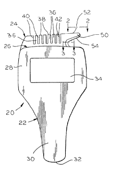
14 As seen in FIG. l, apparatus 20 is a tool for removing
unwanted matter such as cut hair strands and the lixe from in
16 between the cutting surfaces of the blades of a hair clipper. The
apparatus 20 includes a handle 22 and a comb 24 locatea at an end
18 26 of the handle 22. A portlori 28 of the handle 22 is relatively
19 wide, while a portion 30 is tapered to a narrow end 32. An opening
34 may be provided in the handle 22, if desired, for removing
zl detachable blade sets from hair clipper handles. A peripheral rib
22 may also be provided to add structural strength to the apparatus 20
23 if desired.
24 The comb 24 includes a body 39, outer surfaces 41, 43 arid
a plurality of spaced teeth 36 separated by openings 40. The
26 Operiirigs 40 preferably have relatively sharp edges 42. The Comb
2'7 teeth 36 have tips 38, which can be separated by the openings 40,
28 as in FIG. l, or secured to each other, as in FIG. 5.
29 The comb 24 also includes a finger 5o which extends from
an grid 52 of the comb 24 perpendicular to the teeth 36, but
31 parallel to the plane Created by the teeth 36. The finger 50 is
32 generally Contigu0ilS With the tips 38, and forms a recessed portion
33 54 adjacent the body 39 (FIG. 2).
-3-
~~6~4$8
1 The finger 50 and the recessed portion 54 are shown iri
2 greater detail in FIG. 2. The finger 50 is tapered inwardly
3 towards an end 51, and is also tapered inwardly towards the teeth
4 tips 38, as shown in FIG. 4. The recessed portion 54 may lriclude
a tapered area 56, if desired, in which the recessed portion 54
6 tapers inwardly towards an edge 55, as seen in FIG. 3.
7 Another tool for removing unwanted matter from hair
g clippers is shown in FIG. 6. There, apparatus 80 includes a handle
9 82, a comb portion 84 and a brush 86. The comb portion 84 includes
a plurality of spaced teeth 87 separated by openings 88, which do
11 riot extend to an upper edge 90, and a finger 92, which extends from
12 the upper edge 90. The openings 88 could extend to the edge 90, if
13 desired, and a recessed portion 94 can be provided beneath the
14 finger 92.
As seen in FIG. 7, a plurality of relatively small
16 protrusions 98 can be added to the comb portion 88 (FIG. 8). Such
17 protrusions can be added to the comb 24 (FIGS. 1 and 5), as well.
18 The protrusions 98 can be adjacent the edges 42, or any other
19 suitable place.
The apparatus 20 may be used to clean between hair
21 clipper blades of the type shown in FIGS. 8, 9 and 10. A hair
22 clipper 100 includes a handle 102, a stationary blade 104, a
23 reciprocating blade 106 and a spring 108. The stationary blade 104
24 and reciprocating blade 106 each have a row of teeth 110, 112,
respectively, which complement each other so that when the
26 reciprocating blade 106 moves back and forth laterally in the
27 directions of arrow 114 (FIG. 9), hair strands which enter spaces
28 between the stationary teeth 110 are cut by the teeth 112. The
29 spring 108 presses the teeth 112 against the teeth 110 for cutting
purposes, while still allowing the reciprocating blade 106 to move
31 back and forth in the directions shown by the arrow 114. In use,
32 however, cut hair strands and other unwanted matter may accumulate
33 between the blades 110, 112, in an area 120 (FIG. 8). If not
34 removed, these hair clippings can spread the blades so that
additional hair strands which enter the blade teeth are not cut.
_4_
206a48~
1 The apparatus 20 is used 'to clean the area 120 by
2 inserting the finger 50 between the blades 110 and 112, separating
3 them so that the comb 24 can enter the space 120. The end 51 is
4 pressed between the blades just below the teeth of the blades, and
the recessed portion 54 passes between the blade teeth. The taper
6 on the recessed portion 54 eases entry between the blades.
7 The tool 20 is then passed between the blades in the
8 direction of the arrow 122 (FIGS. 9 and 10), and unwanted cut hair
9 strands and the like in the space 120 are removed. When the comb
is removed, the spring 108 presses the blades 104, 106 together
11 again. This process can be repeated as often as necessary,
12 The cut hair strands are removed by the finger 50, the
13 recessed portion 54, the comb teeth 36 and the protrusions 98, if
14 used. The apparatus 20 can be inserted between the blades from
either side of the clipper 100. Also, the upward taper of the
16 outer surfaces 41, 43 of the comb 24 towards the outer edge 51 in
17 FIG. 4 may be set so that the outer surfaces are substantially
18 flush with the inside surfaces of the blades 110, 112. Such a
19 taper is used because the blades are secured inside the clipper,
and are spread by the comb only at the blade teeth, creating an
21 angle between the inside blade surfaces.
22 The many advantages of this invention are now apparent.
23 Hair clippings which accumulate between the clipper blades can be
24 removed easily and efficiently, without disassembling the blades.
Users are more likely to clean the blades often, improving both
26 performance and reliability.
27 While the principles of the invention have been described
28 above in connection with specific apparatus and applications, it is
29 to be understood that this description is made only by way of
example and not as a limitation on the scope of the invention.
-5-