Note: Descriptions are shown in the official language in which they were submitted.
CA 0206~607 l998-06-04
ROTARY PRINTING MACHINE
EQUIPPED WITH AN EXCHANGEABLE CYLINDER
The present invention is related to a rotary
printing machine equipped with an exchangeable cylinder,
especially so a screened ink transfer cylinder also called
"anilox" cylinder, held between the two side walls of the
machine frame by freely disengageable holding and driving
means.
With a view to optimizing the use of rotary printing
machines, exchangeable anilox cylinders have become a feature
more and more thought for.
In fact, depending on the given print motif a very
intensive solid requiring considerable ink quantities or a
fine meshed screen necessitating much less ink, it is possible
either to vary the ink characteristics such as viscosity,
dilution or else to exchange the anilox cylinder of which the
volume of the bits on its surface determines the quantity of
ink transferred. Considering the difficulties to master the
ink homogeneity and viscosity, an increasingly preferable
solution consists in exchangeable anilox cylinders.
The documents FR-E 503 628, W0-87/04665 and EP-315
917 present rotary printing machines equipped with one or
several cylinders and pertaining driving means lodged in a so-
called cassette allowing to be pulled out horizontally from
the machine perpendicularly to the lateral wall it is to
cross.
AS may be gathered, the weight of the exchangeable
assembly comprises the weight of the cylinders to be exchanged
68200-126
CA 0206~607 1998-06-04
but also the weight of the cassette body as well as the
cylinder holding and driving means thereto attached. Handling
of such an assembly will thus be so difficult that the
exchange will not be carried out as often as it should.
On the rotary printing machine presented in the
document US 4,901,641, the printing cylinder 15 is held by two
axles 61 and 65 with tapered ends penetrating into equally
tapered apertures arranged coaxially on both lateral ends of
the cylinder. The axle 61 may be freely advanced or retracted
as required towards, or from, the cylinder in order to seize
or disengage it. Moreover, an ink basin 85 is kept underneath
the printing cylinder by a bracket 86 able to both turn around
and rise or descend along a vertical threaded shaft 91
situated against a lateral wall. The linkage between the
basin and the bracket end is also rotarily movable. The inner
side of the basin is provided with V-shaped half-rigid
supports 114 for the cylinder.
With the bracket rising, the basin will get in
contact from underneath with the cylinder and thus take up its
weight. The cylinder holding axles will then be retracted
and, by double rotation of the basin with regard to the
bracket as well as of the bracket with regard to the threaded
shaft, it will be possible to disengage this printing cylinder
through the upstream side and then on the machine side. It
becomes obvious that the bracket holding at its very end the
basin and the cylinder should be particularly well dimensioned
and that the movement to be carried out for the release of the
cylinder is rather complex for less qualified workers.
68200-126
CA 0206~607 1998-06-04
on the frame crossbars. On these rails would run two
identical trolleys provided on their upper sides with at least
one cylinder support and held together at their end on one
side by a rigid connection enabling to keep a free space in
the carriage centre. It would be useful to add to one of the
carriage rails a rack, and to the corresponding trolley a
device with guides to be actuated by means of a handle so as
to have them engage into the teeth of the rack and thus to
stop the carriage in a precise position.
Worded differently, the carriage may be considered
as a frame movable on the rails and supporting the cylinder at
both its ends, the space in the middle being likely to be used
for means ensuring the first shifting in vertical direction.
According to a first way of realisation, the means
allowing the cylinder to be vertically moved onto the trolleys
supports of the carriage include a parallel table underneath
the cylinder with a length less than the distance between the
trolleys and provided with cylinder supports on its upper
side.
This table is shifted vertically by lifting means
between the upper position against the lower part of the
cylinder, and a lower position situated below the position of
the trolleys, the said table passing through the space
available in the centre of the carriage.
The lifting means of the table may essentially
consist of two brackets arranged X-wise and jointed in their
centre with their ends rotarily movable. At least one of the
ends below the ground level and one of the upper ends below
68200-126
CA 0206~607 1998-06-04
the table are, additionally, movable sidewise and parallelly
to the table. A sensor checks the position either of the ends
movable in upper sidewise direction or of the ends movable in
lower sidewise direction. Preferably, only the ends of the
brackets situated on one side, ie an upper and lower one, are
shiftable sidewise, the sensor being fitted on the ground.
Alternatively, the lifting means of the table
include one or several vertical sensors underneath. If, with
the design thus realized, the table once retracted is fully on
ground level under the carriage, and the device for
disengaging the cylinder will in no way be able to interfere
with the operation of the printing machine.
It would be an advantage to design a workshop
trolley with its own carriage rails situated at identical
height and with identical gauge as the machine carriage rails.
Such a trolley, moreover, includes positioning means allowing
to fix it with regard to the upstream or downstream side of
the frame in such a way that the rails will be situated in the
extension of the machine's rails. Such a trolley might also
include a carriage provided with a space in its centre as
described above.
According to another way of realizing the invention,
the trolley carriage resting on horizontal rails is fitted
close to, and underneath, the cylinder. The means used for
the vertical shifting of the cylinder include then one or
several supports fitted so as to be able to rotate on a
vertical threaded rod engaged in the threaded hole of the
upper side of the corresponding trolley. Alternatively, one
68200-126
CA 0206~607 1998-06-04
or several cylinder supports are raised and lowered as
required by a vertical sensor.
According to another way of realizing the invention,
the carriage includes two stays situated each facing, and
close to, the inner opposite sides of the side walls of the
frame, and fitted on crossbars, every stay bearing in the
propinquity of, and underneath, the cylinder a horizontal bar
protruding from the frame with each end provided with a
stopping plate, both bars being held one with regard to the
other by at least one horizontal crosswise bar. The means for
the vertical shifting of the cylinder consist of a jack-type
device raising and lowering the cylinder holding and driving
means.
These simplified versions are actually foreseen for
occasional fitting and dismantling so as to allow the
withdrawal of the cylinder for repair and cleaning. In such a
case, the horizontal carriage is preferably fitted closely
after the cylinder, which solution allows to dispense with the
precedent table by using raising or lowering trolley supports
covering a short distance or else a device raising or lowering
the holding and driving means of the cylinder equally through
a short distance.
If the exchangeable cylinder is held and driven by
two taper-end pieces fitted for rotary motion, facing the side
walls and engaging in the coaxial tapered orifices on the
corresponding cylinder sides, one of the pieces being rotated
and the other one allowing to be withdrawn as required so as
to disengage the cylinder, it has appeared to be appropriate
68200-126
CA 0206~607 1998-06-04
to have every lateral ends of the exchangeable cylinder
protruded by a concentric rim the inner side of which has a
tapered part directed towards the inner side of the cylinder,
and exchangeable cylinder holding and driving pieces having
the shape of tapered disks, their largest diameter exceeding
the smallest inner diameter of the corresponding rim. As a
useful feature, one of the disks includes a concentric pusher
held against the corresponding side of the cylinder so as to
disengage the end rim from the disk with the opposite disk
being in retracted position.
As will be easily understood, the contact surface
between the driving piece and the cylinder side corresponds to
the circumference of a disk with a larger diameter. This
contact surface can thus be reduced, thereby enabling an
easier disengagement.
The invention is described hereafter more in detail
by means of sample executions without, though, imposing any
limits, and illustrated by the attached drawings on which:
- Fig. 1 is schematic perspective view of a printing
machine containing a first execution of the device for
disengaging an exchangeable cylinder;
- Fig. 2 is a schematic perspective view of a workshop
trolley preferably used with the machine according to Fig. 1;
- Fig. 3 is a perspective view of a printing machine
provided with a second execution of a device for disengaging
an exchangeable cylinder removed occasionally and laid on a
conventional workshop trolley; and
- Fig. 4 is a perspective view of a printing machine
68200-126
CA 0206~607 1998-06-04
provided with a third execution of a device for disengaging an
exchangeable cylinder removed occasionally and laid on a
conventional workshop trolley.
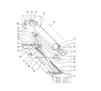
For better understanding of Fig. 1, the frame 10 of
the rotary printing machine is shown, although in its full
shape, only in dotted lines, the cylinders situated above the
anilox cylinder 15 such as the plate cylinder and the
impression rollers being not represented. Similarly, the
exchangeable anilox cylinder 15 is represented with a shorter
shape than in reality so as to allow the maintenance and
driving means to be shown in a more obvious way. In this
printing machine, the inking device consists essentially of a
lengthwise chamber 11 applied against the anilox cylinder 15
and within which ink circulates before being scraped off the
cylinder by an upper and a lower blade.
Every side of the anilox cylinder 15 is extended by
a rim 17 having the same diameter as the cylinder itself and
an inner surface in the shape of a tapered part 19 directed
towards the inner cylinder space. This tapered part 19 can be
realized for instance with the shape of chamfer on the inner
circular edge. The anilox cylinder 15 is held between two
disks 40 and 41 the circumference 43 of which is also tapered
and directed towards the cylinder. The disks 40 and 41 are
fitted for free rotation on each side of the frame 10 with, if
necessary, a jack-type device 42 so as to allow the cylinder
15 to be slightly raised or lowered against the printing
cylinder which is not represented. The installation of the
disk 40 also includes a device 44 with hydraulic or pneumatic
68200-126
CA 0206~607 1998-06-04
jacks enabling the disk 40 to be moved forward or backward as
required with regard to the cylinder 15. In this way, if the
device 44 is actuated, it is possible to engage the tapered
circumferences 43 of the disks 40 and 41 as required into the
equally tapered parts 19 of the sides of the cylinder 15 which
will simultaneously seize, centre and rotate it owing to the
considerable friction forces appearing at the tapered
junction. The disk 41 comprises in its centre a pusher 45, ie
an inner coaxial piston the outer side of which visible on
Fig. 1 can be moved forward by an inner sensor (not
represented) towards the corresponding side of the
exchangeable cylinder 15.
The device for disengaging the anilox cylinder 15
includes a vertically movable table 30 and a horizontal
carriage 20. As illustrated, the table 30 provided on its
upper side with several cylinder supports 37 is held by two
brackets arranged X-wise and centre-jointed for rotation. The
upper end of the bracket 32, represented in the foreground of
Fig. 1, is fitted underneath the table 30 so as to effectuate
rotations. Similarly, the lower end of the bracket 31,
equally shown in the foreground of Fig. 1, is fitted to
effectuate rotations, though on the ground. On the other
hand, the upper end of bracket 31 is both movable rotarily and
sidewise underneath the table 30 owing to the casters 34.
Similarly, the lower end of the bracket 32, represented in the
background of Fig. 1, is movable both rotarily and sidewise
along the ground owing to the casters 35. The position of the
lowered end of the bracket 32 is determined by a sensor 38
68200-126
CA 0206~607 1998-06-04
imposing vertically the height of the table 30 by the
kinematics of the crossed brackets. The sensor 38 may
indifferently be a hydraulic or pneumatic jack, or even a
threaded rod rotarily movable, driven by an electric motor and
passing through a tapered orifice arranged in the lower part
of the bracket 32. As illustrated on this Fig. 2, the table
30, when in retracted position, will be positioned between two
crossbars 12 of the frame 10.
The carriage 20 includes two rails 21 and 21' fitted
close to the ground, opposite one another and against the side
of the frame 10, the said rails being preferably also
supported by the crossbars 12 on the ground. The rails 21
guide an identical trolley 22 provided on its upper side with
two cylinder supports 24. These two trolleys 22 in the
foreground and background of Fig. 1 are rigidly held together
at their downstream end by a rod 26, thus ensuring a rigorous
correspondence between the supports of the cylinder 24 placed
opposite one another. As may be noticed better on the rear
rail 21, the latter is provided with a rack 27 the teeth of
which can be engaged by a dog belonging to a locking device 29
itself actuated by a handle 28.
Fig. 2 illustrates a workshop trolley 16 designed
for carrying one or several anilox cylinders 15 from one
printing machine to the other. As a particular feature, the
upper side of this trolley is provided with a carriage 20
identical to the one described previously and mounted on two
rails 121. Moreover, the longitudinal sides of the trolley 16
have two apertures 14 which in joint action with the bolts 13
68200-126
CA 0206~607 l998-06-04
fitted on the crossbar 12 of the frame 10 on the machine
illustrated by Fig. 1 allow the positioning of the trolley 16
along the upstream side of the frame 10 in such a way as to
enable the trolley rails 121 to be situated as an extension of
the machine rails 21. In this way, the machine carriage 20
can be rolled on or off the trolley 16.
At the end of the rails 21 of the frame 10, safety
devices are foreseen for the purpose of stopping the trolleys
of the carriage 20 at the outlet of the frame 10 if a workshop
trolley 16 is not appropriately positioned, ie if the
positioning means 13 and 14 are not engaged in one another.
As already described precedently, the machine
operates in the following way. With the anilox cylinder 15
being initially held between the two disks 40 and 41, the
operator is to order the retraction of the sensor 38 which
action entails the raising of the table 30 until the supports
37 touch the lower part of the cylinder 15. The device 44 is
then switched on so that the disk 40 will be pulled out of the
rim 17 at the end of the cylinder 15. In most cases, the
cylinder will nonetheless not disengage from the disk 41
entailing the necessity to order the pusher 45 to move forward
so as to slightly shift this cylinder 15 lengthwise until the
tapered circumference 43 will come out of the rim 17.
As soon as the cylinder 15 iS disengaged from its
holding and driving means 40 and 41, the operator is able to
order the extension of the sensor 38, which action causes the
lowering of the table 30 until the latter will move into the
centre of the carriage 20. At that stage, the ends of the
11
68200-126
CA 0206~607 1998-06-04
cylinder 15 are seized by the supports 24 of the trolleys 22
and 22' whereas the table 30 continues its movement up to full
retraction, ie between the crossbars 12. The anilox cylinder
15 resting now on the carriage 20 can be shifted orthogonally
with regard to the lengthwise horizontal axle along the rails
21.
In line with a first possibility, the carriage 20
has on its upper side at least 2 pairs of supports 24, the
second pair being already used for carrying the second anilox
cylinder 15 desired. In such a case, the simple shifting of
the carriage 20 allows to move the second cylinder desired
above the table 30 which is still in retracted position
whereas the carriage is interlocked in position by an end stop
device 29. Hence only a new rise of the table 30 is to be
ordered so as to have it carry off the new cylinder 15 until
opposite the holding and driving disks 40 and 41 which will
then be tightened again thus ensuring the cylinder to be
seized.
With a second possibility, an empty workshop trolley
16 is previously placed and fixed along the upstream side of
the frame 10. Thereupon, the carriage 20 carrying the
cylinder 15 is rolled from the rails 21 of the frame 10 onto
the rails 121 of the trolley 16, thus enabling the cylinder to
be carried out of the machine for subsequent operation. Then,
by means of another trolley 16, a new cylinder 15 is brought
on site and put into the lower part of the printing machine.
Fig. 3 illustrated a printing machine from which the
anilox cylinder 15 is only supposed to be withdrawn for
12
68200-126
CA 0206~607 l998-06-04
cleaning or repair. On this figure, the parts similar to
those described earlier on Fig. 1 are identified with
identical references. In this case, the carriage 20 iS each
time fitted and then dismantled, which action is accomplished
higher up and closer to the cylinder 15, thus allowing to
dispense with the automatic table 30 previously described. As
represented by the illustration, two rails 21 and 21' but of
greater length are fitted opposite one another closely to, and
parallelly with, each side of the frame 10. Every rail 21
rests on a conventional workshop trolley 116 as well as on a
support 49 SO as to enable the height adjustments to a certain
extent. According to illustration, the support 49 includes a
threaded rod 47 held within a bushing 48 but allowing to be
turned manually for raising or lowering the rod.
A carriage 20 movable on the rails 21 iS initially
shifted so as to allow a pair of supports 24 to be positioned
under the anilox cylinder 15. Owing to the rising threaded
rods 47 acting immediately underneath the rails 21, the entire
carriage 20 can be raised as far as to allow the supports 24
to pick up the cylinder 15 which can then be disengaged from
the holding and driving means 40 and 41.
With an anilox cylinder 15 disengaged, the carriage
20 is slowly rolled along the rails 21 as far as to allow the
cylinder to be placed above the supports 37 of the workshop
trolley 116. These supports 37 are also fitted for rotation
on the threaded rods passing through the threaded rings which
latter can be turned by means of a handle. Turning the rims
causes the supports 37 to rise in such a way as to seize the
13
68200-126
CA 0206~607 1998-06-04
cylinder 15 and to lift it sufficiently, disengaging the
supports 24 of the carriage and enabling its withdrawal.
Alternatively, the carriage supports 49 are fixed or
else substituted by case piles and supports 24 on trolleys 22
are fitted for free rotation on the threaded vertical rods 25
engaged in threaded orifices 23 on the upper side of the
trolleys 22. Hence, the cylinder is then seized not by the
rise of the entire carriage 20 but by the rise of each support
24 with regard to the carriage.
Fig. 4 illustrates a carriage 50 consisting of two
stays 55 based on the crossbars 12 and fitted on either side
of the frame by means of the bolts 59. Every stay supports at
its upper end close to, and under, the cylinder 15 a
horizontal bar 56 provided on its upper side with a rubber
coating 58 and with a stopping plate 54 at both ends. One of
the ends of each of these horizontal bars protrudes from the
downstream side of the frame 10. Preferably, both horizontal
bars are held by an intermediate crossbar 52 with regard to
one another.
The empty workshop trolley 116 is provided on its
upper side with cylinder supports 37 fitted on threaded axles,
themselves engaged on threaded rings which can be rotated by
means of a handle for raising or lowering these supports as
required. This trolley is previously moved under the ends of
the horizontal bars 56 protruding from the frame. At that
stage, the jack device 42 is then actuated in order to lower
the holding disks 40 and 41 until the cylinder 15 will be
positioned on the horizontal bars 56, whereupon the device 44
14
68200-126
CA 0206~607 1998-06-04
for withdrawing the disk 40 is actuated in order to disengage
the cylinder. Then, the cylinder 15 can be slowly rolled
along the bars 56 until it will be stopped by the plates 54.
By lifting the supports 37, it will be possible to pick up the
disengageable cylinder by means of the trolley. Another
cylinder can then be put in by inverse procedure. If
necessary, the carriage 50 can be dismantled when not used.
Numerous improvements can be added to this machine
within the limits of this invention.
14a
68200-126