Note: Descriptions are shown in the official language in which they were submitted.
2 ~
--1--
INTERNAL COMBUSTION ENGINE HAVING
AN INTEGRAL CYLINDER HEAD
Back~roulld Of The Invention
This invention relates to internal combustion
engines, and more particularly to engines having an
integral cylinder head.
Many types of internal combustion engine
designs are known for use in lawnmowers, generators,
snowblowers and the like as well as for motor vehicles.
In a typical prior art engine design, the engine housing
is made of at least three distinct engine housings.
Typically, there is a separate housing for the cylinder
head that encloses the cylinder bore and the valves, and
at least two additional housings for enclosing the other
engine components. A cam shaft cover is also used to
enclose the cam shaft in overhead cam (OHC) engines. The
need for these engine housings requires additional die
casting and assembly steps in the engine manufacturing
process. These additional steps increase the cost of the
engine.
Conventional engine designs require that the
cam shaft be mounted in bossas affixed to the inside of
the engine housing. These designs require additional or
more complex assembly steps to insert the cam shaft into
the engine housing. Separate cam shaft bearing
components must also be manufactured and inserted about
the cam shaft, resulting in additional manufacturing and
assembly cost.
The crankshaft in conventional engine designs
is typically disposed within opposite apertures machined
in the engine housing side walls. These designs also
increase the assembly time and require that separate
crankshaft bearings be manufactured and placed around the
crankshaft, further increasing the manufacturing and
assembly cost.
The difficulty in assembling the conventional
crankshaft and connecting rod components require that a
:
2 ~
--2--
two piece connecting rod be used to connect one end of
the rod to the crankshaft throw. The two pieces of the
connecting rod are typically bolted together by a pair of
bolt assemblies. The need for a multi-piece connecting
rod and the bolt assemblies also results in increased
manufacturing and assembly costs.
In conventional overhead cam engines, the cam
shaft is driven hy a timing belt or chain assembly.
Prior art timing belt drives have several disadvantages.
First, the idler pulley must be adjusted so that the belt
has the correct amount of tension. If the tension is too
low, there is a risk that the belt will jump a tooth on
the sprocket, causing improper engine timing. If the
t~nsion in the timing belt is too high, the belt and the
bearings tend to wear prematurely.
A second disadvantage of prior art timing
belts is that they typically require a belt guard or
cover to keep dehris off of the belt. A third
disadvantage is that they typically require an oil seal
on the cam shaft.
Chain assemblies used to drive cam shafts
also have several disadvantages. First, chain drives,
like belt drives, require an idler sprocket to adjust the
tension. Second~ chains require lubrication and are
difficult to assemble. Third, chain drives require a rub
rail on the outer side of the chain to keep the chain
from slipping.
One obsolete method for driving the cam shaft
used bevel gears. However, such bevel gears typically
required very small center line and axial alignment
tolerances, on the order of about + 0.001 inches. These
small, critical tolerances require precision machining of
the bevel gears at increased expense.
Typical small internal combustion engines
require one or more additional shafts mounted to the
inside of the engine housing to operate the oil slinger
for engine lubrication and the engine governor for
'
2 ~
controlling engine speed. These additional sh~fts also
require extra manufacturing and assembly steps, thereby
further increasing the cost of the engine.
Therefore, it is desirable to reduce the
number of engine housings, bearings, shafts and other
component parts to decrease the manufacturing and
assembly costs of an internal combustion engine.
Summary Of The Invention
An internal combustion engine is disclosed in
which the number of distinct housings, shafts, bearings
and other components is decreased to achieve substantial
savings in manufacturing and assembly costs.
In its broadest form, the invention comprises
an internal combustion engine having a first engine
housing that includes a cylinder bore and an integral
cylinder head, disposed near a first end of the housing.
A first surface disposed near a second end of the housing
is adapted to create an interface with a second surface
on a second engine housing, with the crankshaft also
being disposed near or at the interface between the two
housings. This arrangement enables the crankshaft
bearings that encircle and retain the crankshaft to be
formed integrally with the first and second engine
housings at the first and second surfaces respectively.
This configuration also enables a one-piece connecting
rod and a built-up or two~piece crankshaft to be used~
In one embodiment of the invention employing
an overhead cam shaft, the drive means for driving the
cam shaft includes two gParsets of cross-helical or non-
enveloping worm gears. The drive or driven gears in each
gearset may also be made from a plastics material
containing nylon or phenol to further reduce costs.
Also in the overhead cam (OHC) embodiment,
the OHC drive shaft or cross shaft is also used as both
the shaft for the oil slin~er and the speed governor,
there~y eliminating the need for additional shafts to
drive these components. The auxiliary power take off
'
, :
.
2 ~ 3
--4--
used for example to drive the wheels of a lawnmower is
also directly connected to the cross shaft, thereby
eliminating intervening gears and other components.
In a second embodiment of the invention, both
the crankshaft and the cam shaft are disposed near or at
the interface between the first engine housing and the
second engine housing. This unique design also enables
the cam shaft bearings to be integrally formed in the
first surface and in the second surface of the first and
second housings respectively, thereby eliminating the
need for separate bearing components.
It is a feature and an advantage of the
present invention to reduce the number of distinct
components in an internal combustion engine to thereby
decrease the cost of manufacturing and assembling the
engine.
It is yet another feature and advantage of
the present invention to reduce engine costs by
integrating the cylinder head with one of the other
engine housings.
It is yet another feature and advantage of
the present invention to reduce engine costs by disposing
the crankshaft andlor the cam shaft at the interface
between the separate engine housings.
It is yet another feature and advantage of
the present invention to reduce engine costs by forming
the crankshaft and/or cam shaft bearings integral with
the engine housings.
It is yet another feature and advantage of
the present invention to reduce engine costs by using a
one-piece connecting rod and a two-piece crankshaft.
It is yet another feature and advantage of
the present invention to reduce OHC engine costs by the
OHC drive shaft to drive both the oil slingex and the
speed governor.
It is yet another feature and advantage of
the present invention to reduce OHC engine costs by using
~, . '
-: . -, ;
, ~ ~
- ' . ' ' ' ~ :
,
2 ~
OHC drive gears having less precise tolerances made from
inexpensiv~ plastic materials.
It is yet another feature and advantage of
the present invention to reduce OHC engine costs by
directly connecting the auxiliary power take off shaft to
the OHC cross shaft without intervening gears or other
linkage components.
These and other features of the pressnt
invention will be apparent to those skilled in the art
from the following detailed description of the preferred
embodiments and the attached drawings, in which:
Brief Description Of The Drawinqs
Fig. 1 is a side view of an overhead cam
engine, shown in partial section.
Fig. 2 is a partial sectional side view of
the OHC engine of Fig. 1, the engine having been rotated
9oo clockwise about its longitudinal axis.
Fig. 3 is a top view of the engine depicted
in Figs. 1 and 2 with the cam shaft cover removed,
depicting the overhead cam shaft.
Fig. 4 is a partial sectional side view of
the drive means for driving the overhead cam shaft and of
the oil slinger and governor assemblies of the engine
depicted in Figs. 1-3.
FigO 5 is a partial sectional side view of
the first embodiment depicted in Figs. 1-4, depicting a
one-piece connecting rod with the piston at top dead
center.
Fig. 6 is a partial sectional side view
similar to Fig. 5 but rotated 90 clockwise about the
; engine's longitudinal axis, depicting the piston at
bottom dead center.
Fig. 7 is a top view of an engine housing
; according to the second embodiment of the present
invention, depicting both the crankshaft and the cam
shaft being disposed at the interface between the two
engine housings.
,:.. ,.. , ., ~
': :
'
~. ,
2 ~ 2 ~
--6--
Detailed Description of The Preferred Embodiments
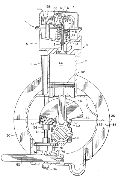
In Figure 1, engine l includes a first engine
housing 2 and a cam shaft cover 3 that encloses overhead
cam shaft 4. Formed integral with overhead cam shaft 4
is a cam 6 for operating the bucket tappet 8 of an
exhaust valve 10, the valve consisting of a valve stem 12
and a spring 14. Similarly, cam 16 disposed on cam shaft
4 operates intake valve 18 by engaging intake bucket
tappet 20. Intake valve 18 also includes a valve stem 22
and a spring 24.
First engine 2 includes a first surface 26
which forms an interface 86 (Fig. 2) with a second
surface 2~ of a second engine housing 30. Crankshaft 32
is disposed at the interface between first surface 26 and
second surface 28. A first pair of spaced bearing cap
sections 34 and 36 are also formed integral with first
surface 26. Similarly, a second pair of spaced bearing
sections 38 and 40 are formed integral with second
surface 28 of the second engine housing. Bearing section
34 opposes bearing section 38, and bearing section 36
opposes bearing section 40. Bearings 3~, 36, 38 and 40
are formed integral with their respective engine housings
to reduce cost, and are disposed near interface 86.
A piston 42 disposed within cylinder bore 44
is connected to crankshaft 32 by a two-piece connecting
rod 46. One end of connecting rod 46 is connected to
piston 42, and the opposite end of rod 46 is connected to
crankshaft 32 at crankshaft throw 48. The two pieces of
the connecting rod are held together by a pair of bolt
assemblies 50. The reciprocating and vibrational forces
of the piston are opposed by a pair of counterweights 52
and 54 connected to the crankshaft.
Overhead cam shaft 4 is rotatably driv~n by a
drive means consisting of a first gearset 56 and a second
gearset 5~. Gearsets 5~ and 58 are preferably comprised
of pairs of cross-helical gears because such gears do not
require precise tolerances. The cross~helical gears only
.. ~ ., , . , .,, .... , .... ,, . ~ , .. . .. .... . .. ...
' '` '` ' ' . `. . ' '
.
: ,
. ' ;` - ' , ' .
:: '
~0~2a
require a center distance tolerance of about + 0.004
inches. The axial alignment tolerance for the cross-
helical gears in the present invention is in the range of
between about + 0.060 to + 0.070 inches. However, bevel
or other types of gears may also be used for gears in
gearsets S6 and 58.
First gearset 56 includes a crankshaft drive
gear 60 and a driven gear 62 interconnected with the
drive or cross shaft 64. Second gearset 5B includes a
cross shaft drive gear 66 and a cam sha~t driven gear 68.
Rotation of crankshaft 32 causes the drive means to
rotate cam shaft 4 at twice the speed of the crankshaft
to operate the intake and exhaust valves.
Instead of being mounted on a separate shaft
to the inside of the engine housing, oil slinger 70 is
directly mounted onto cross shaft ~4 and rotatable
therewith. Oil slinger 70 distributes or splashes oil to
lubricate the moving components of the engine.
Several components of the engine speed
governor are also directly connected to cross shaft 64.
Specificallyl a pair of centrifugally-responsive
flyweights 72 and 74 are disposed about cross shaft 64
and adjacent to oil slinger 70. The rotation of cross
shaft 64 causes flyweights 74 and 76 to move in a radial
direction away from cross shaft 64 at higher engine
speeds, thereby causing a governor spool 78 to engage a
governor actuating arm 80. The movement of arm 80 moves
a governor lower arm 82 interconnected therewith. In
turn, the movement of lever arm 82 moves the throttle
plate of the engine carburetor to adjust engine speed.
Also directly connected to cross shaft 64 is
an auxiliary power take off shaft 84, which may be used
to operate the wheels of a lawnmow~r or other
accessories. The direct connection of shaft 84 to cross
shaft 64 eliminates the need for any intervening gearsets
or other mechanical linkages.
,,
,
~ ` ~ ' ' `
2 ~ 2 ~
Figure 2 is another side view of the engine
of Figure 1 shown in partial section. In Figure 2 as in
all of the Figures, components having corresponding
functions have been given the same numerical
designations.
Figure 2 more clearly depicts the interface
86 between first surface 26 and second surface 28. It is
clear from Figure 2 that crankshaft 32 lies at the
interface 86. This positioning of the crankshaft
decreases the cost and time required to assemble the
engine since crankshaft 32 may be simply laid onto either
first surface 26 or second surface 28 without fitting the
crankshaft through apertures in the side wall of the
engine housing, as in conventional engine designs.
Figure 2 also more clearly depicts the gears
in first gearset 56 and in second gearset 58.
Specifically, Figure 2 depicts crankshaft drive gear 60
engaging cross shaft driven gear 62. Similarly, Figure 2
depicts cross shaft drive gear 66 engaging cam shaft
driven 68.
As depicted in both Figures 1 and 2, cylinder
head 5 is formed integral with first engine housing 2 to
decrease manufacturing and assembly cost. Figure 2 also
depicts a two-piece connecting rod 46 which is held
together by bolt assemblies 50 as described abovP in
connection with Figure 1.
Figure 3 is a top view of the engine depicted
in Figures 1 and 2. Figure 3 more clearly depicts the
engagement of gears 66 and 68 in second gearset 58.
Figure 3 also depicts the spatial relationship between
cams 6 and 16 and their respective valve assemblies 10
and 18.
Figure 4 is a partial cross sPctional side
view which more clearly depicts the drive means used for
driving the overhead cam shaft. As shown in Figure 4,
cross shaft 64 is retained by bearings 88 and 90, which
are preferably integral with the first engine housing.
~, '
_9_
Figure 4 also more clearly depicts the
configuration oE centrifugal flyweights 74 and 76 and
their relationship to governor spool 78. As cross shaft
64 rotates, flyweights 74 and 76 move in a radially
outward direction from the cross shaft, causing their
respective dog legs 74a and 76a to engage a flange 78a on
spool 78. This engasement causes spool 78 to move in an
axial direction away from oil slinger 70 to engage
governor actuating arm 80. The movement of actuating arm
80 causes the engine speed to change via governor lever
82 as discussed above in connection with Figure 1.
Figure 4 also depicts auxiliary power take
off (PT03 shaft 84 which is directly connected and
preferably an integral part of cross shaft 64. Auxiliary
PTO shaft 84 is used to drive the wheels or other
accessories as discussed above.
Figures 5 and 6 depict the piston, connecting
rod and crankshaft assembly in which a one-piece
connecting rod 92 is used instead of the two~piece
connecting rod 46 depicted and described above in
connection with Figures ~ and 2. The use of a one-piece
connecting rod 92 may require that crankshaft 32 be made
of several pieces to enable the engine to be easily
assembledO The use of a one-piece connecting rod may
have certain cost advantages over the two~piece
connecting rod discussed aboveO
Figure 7 depicts a second embodiment of the
present invention in which both crankshaft 32 and cam
shaft 94 are disposed at the interface between first
surface 26 (Figs. 1 and 2) and second surface 28. In
this second embodiment, cam shaft 94 is encircled by two
sets of spaced cam shaft bearing cap sections 96 and 98.
Bearings 96 and 98, including their counterpart spaced
sections on the second engine housing, are formed
integral with their respective engine housings to
eliminate the need for separate bearing components.
.
2 ~
--10--
Cam shaft 94 rotates in timed relation to
crankshaft 32 by way of a timing gear 99, interconnected
with the crankshaft that engages a cam gear 100
interconnected with cam shaft 94. Although Figure 7
depicts a two-piece connecting rod 46, a one-piece
connecting rod like rod 92 discussed above may also be
used. If a one~piece connecting rod is used, it may be
necessary to use a multi-piece crankshaft.
Although particular embodiments of the
present invention have been shown and described, other
alternate embodiments will be apparent to those skilled
in the art and are within the intended scope of the
present invention. Thus, the present invention is to be
limited only by the following claims.
-- . -- .... . ..
.
.
,: