Note: Descriptions are shown in the official language in which they were submitted.
2065692
STANDING AID FO~ USE ff~TH Æ CHEC~OUT COUNTER
~ TECE{NICAL FIEi,D
The- present invention rela-l:es to checkout counters and
5 more particularly to a standing aid for use with checkout
counters in the retailing and supermarket industries.
~ ~ - ,-- .
B~CKGROUN~ OF I2-~YF.~TION
Checkout counters, such as thos~ used in the retailing
10 and supermarket industries, typically require that the operator
of the checkout counter stand ~or long periods of time,
regardless of whether the current activity level is low or
high. As is commonly ~nown, standing f~r long periods of time
places undue stress on the feet, legs and lower back, causing
15 muscle and joint fatigue and discomfort.
U.S. Patent No. 4,953,664 of Vrooman, et al addresses
the problem of fatigue in operators of such checkout counters
by providing a comprehensive checkovt counter system for
supermarket and merchandising industries. The checkout counter
20 system includes a chair which allows the operator to sit and
rest during periods of low activity. The chair can be swung
out of the way to allow the operator to work while standing
during periods of higher activity and is adjustable both
vertically and horizontally. Unfortunately, many existing
25 checkout counters cannot readily be provided with such a
chair. Also, those individuals responsible for supervising
checkout counter operators may be reluctant, for diverse
reasons, to provide such a chair for the operators.
Accordingly, i~ can be seen that a need yet remains
30 for an aid for use with a checkout counter to provide some
relief from fatigue caused by wo.king while standing for long
periods of time. It is to the ~rovision of such an aid that
the present inventicn is primarily dirested.
- 2 -
2065692
~, .
SUM~ARY OF THE INVENTION
Briefly described, i.n a preferred form the present
invention compris.es ia standing aid for use with a checkout
counter to assist an oper-ator of the checkout counter while
5 standing above the floor. The.standing aid includes a base
frame adapted to be securely-mounted above the floor adjacent
the checkout counter and.a butt~cks cushion adapted for
engaging the buttocks.o~ the operatvr of the checkout counter
while standing. Suppo~t means.-are m~nted.to the base frame
10 for selectively movably supporting the buttocks cushion above
the floor in both a plurality of vertical..positions and a
plurality of lateral positions relative tn the base frame.
Furthermore, the buttocks ~cushion is pivotally mounted to the
support means.
Preferably, the support means comprises a first
stanchion pivotally mounted to the base frame, and including a
first or lower portion and a second or upper portion extendably
mounted to the lower portion. The ~utt:ocks cushion is mounted
to the upper portion of the first stancllion. The support means
20 also includes a second stanchion pivotally mounted at first end
thereof to the base frame, including a ~irst or lower portion
and a second or upper porti.on extendably mounted to the first
portion. The second stanchion is pivotally mounted at a second
end thereof, opposite the first end, to the first stanchion.
Preferably, the standing aid also includes a foot rest
selectively movably mounted to the base frame for movement
among a variety of selected positions.
With this construction, the standing aid is adaptable
for use by operators of a broad range of heights by extending
30 or retracting the upper portion of the first stanchion. Also,
the angle of the first stanchi.on can be adjusted by extending
the upper portion of tlle second stanchion to aid the operator
while standing generally upright (such as during times of high
activity) and to aid the vperator while leaning backwardly
35 (such as during periods of low or no activity). Furthermore,
-- 3
2065692
such a standing aid is adaptable for use with existing, already-
installed checkout counters.
Accordingly, the present invention seeks to provide a
standing aid for use with a checkout counter which is durable in
construction, economical to manufacture, and effective in use.
In addition to the above aspect of the invention, it also
seeks to provide a standing aid for use with a checkout counter to
assist an operator of the checkout counter while standing above a
floor, comprising a base frame adapted to be mounted above the
floor adjacent the checkout counter, a buttocks cushion adapted
for engaging the buttocks of the operator of the checkout counter
while standing, and support means mounted to the base frame for
movably supporting the buttocks cushion above the floor in a
plurality of lateral positions, the buttocks cushion being
pivotally mounted to the support means. The support means
comprises a first stanchion pivotally mounted to the base frame at
a lower end thereof and includes a lower portion and an upper
portion extendably mounted to the lower portion, the first
stanchion being capable of forward pivotal adjustment. A second
stanchion is pivotally mounted at a lower portion thereof to the
base frame and includes an upper portion extendably mounted to
the lower portion, the second stanchion being pivotally mounted at
the upper portion thereof to the first stanchion.
Accordingly, a standing aid is for use with a checkout
counter and which is useful for providing relief to an operator
from fatigue from standing for long periods of time, the standing
aid can be provided as a retrofit for existing checkout counters,
it is adaptable for use by operators of various heights, and for
aiding the operator of the checkout counter while leaning
backwardly.
Other aspects, features and advantages of the present
invention will become apparent upon reading the following
specification in conjunction with the accompanying drawing
figures.
~s,;
~ - 4 -
~ 2065692
BRIEF DESCRIPTION OF THE DRAWING FIGURES
Fig. 1 is a perspective, schematic illustration of a
standing aid according to a preferred form of the invention.
Fig. 2 is a schematic, side view of the standing aid of
Fig. 1, shown positioned adjacent a checkout counter and shown
being used by an operator of the checkout counter while standing
generally upright.
Fig. 3 is a schematic, side elevation view of the
standing aid of Fig. 1, shown positioned adjacent a checkout
~'
~ - 4a -
206S692
~_ .
counter and schematically showing ranges cf motion of a
buttocks cushion portion thereof and of a footrest portion
therèof. - -
Figs. 9A and ~ ar~ a perspec~ivQ, partially e~ploded
5 view and a top, partially sectiot~al view, respectively, of apivoting joint construction por~ion of the standing aid of
Fig. 1.
Fig. 5 is-a eerspecti~e, schematic illustration of a
portion of the standing aid of Fig. 1.
Figs. 6A and 6B-are a schematic, perspective view and
a plan view, respectively, of a ~odified form of the standing
aid of Fig. 1.
Fig. 7 is a perspective, partially cut away
illustration of a standi-n~ ai~ in a second preferred form of
lS the invention includirlg-electric actuating means.
Fig. 8 is a perspective, schematic illustration of a
standing aid in a third preferred form of the invention
including double acting ~s crlinders for raising and lowering
and for laterally adjusting the buttocks cushion thereof.
Fig.s. 9A through qC are schematic, side elevation
views of the standing aid according to the present invention
showing an operator of a checkout counter using the standing
aid while standing su~stantially upri.gllt, while leaning
backwardly slightly, and while partially seated, respectively.
DETAILED DESCRIPTIQN
Referring now in detail to the drawing figures,
wherein like reference characters denote like parts throughout
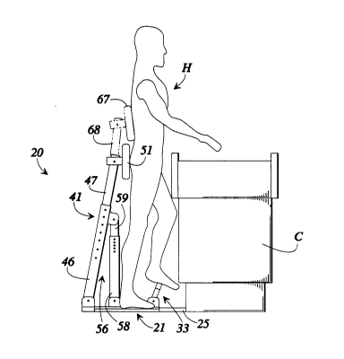
the several views, Fig. l shows a standing aid 20 according to
30 a preferred form of the invention and adapted for use with a
checkout counter. The standing aid 20 includes a base frame 21
comprising a rectangular ~ase panel 22 for positioning atop the
ground or flooring. A first elongate reinforcement beam 23 is
secured to one side of base panel 22 alollg one side edge5 thereof. The elongate rein~orcing beam ~3 is abutted by
-- 5
~ 206~692
.
anotller elonqate reinforcing beam 24 exten-ling perpendicularly
thereto from a central portion of elongate reinforcing beam 23
to a distal side edge 26-of bas-e panel 2~. In this way, the
elongate reinforcing beams 23 and 24 ~orm a T-shaped
5 structure. Each of the elorlgate rein~orcing beams 23 and 24 is
formed of rectangular metal tubing. Foam fatigue mats can be
placed on the base panel 2~ on each side of the beam Z4.
Elongate beam ~ is hollow and ~elescopicallY receives
therein an elon~ate mounting bracket 25 for mounting the
10 standing aid 20 to a-checkout count:er, su~ll as checkout counter
C shown in Fig. 2, and islcludes a bolt flange 25a for this
purpose. Elongate be~m Z4 and elorlgate mounting bracket 25
include means for se]ectively securing the elongate mounting
bracket in place relative to ~longate bea~. 24, and such means
15 will be discussed in more detail below in connection with
Fig. 5.
First and second brackets Z7 and 28 are securely
mounted to an upper surface 29 of elongate reinforcing-beam
24. Bracket 27 is positioned at one end of the reinforcing
20 beam adjacent side edge 26 o base panel 22, while the other
bracket 28 is positioned generally distal therefrom, at a
position approximate]y between one-half and three-fourths of
the length of the reinforcing be2m 24 from the side edge 26 of
base panel 22. Each of the brackets 27 and 28 is made up of a
25 pair of upstanding ears or tabs, such as ears 31 and 32 of
bracket 27.
A footrest 33 is secured to t~-le base frame 21 with the
use of the bracket 27. The footrest 33 includes a short
upright portion 34 and an elongated foot engaging portion 36
30 securely mounted to the short upright portion 34. The footrest
33 is mounted to the bracket 27 for pivotal movement about an
axis 37 extendillg through the bracket 27. As will be discussed
in more detail below, means (unshown in Fig. 1) are provided
for selectively securina t:lle ootrest in any of its various
35 possible angular positions with respect to base frame 21.
2065692
A large upright stanch.~on 41 is pivotally mounted to a
bracket 42, which in tu~n is mounted to elongate beam 23, for
pivotal movement about axis 43 in the dire~tion of
double-headed direction.arrow.4~;. Large;upright stanchion.41
5 includes a first or lower porkion 46 and a second.or upper
portion 47. The lower port.ion.46 is.made..up of an elongate
rectangular tubing and ha~ing a series.of~apertures 48a through
48g formed-in one side 4g.thereof.
Upper or second portion 47 of stanchion 41 is
10 telescopically (extendably) recelved~with~n lower.por~ion 46.
A buttocks-engaging cushion 51 is pi~Jotally mounted to the
upper portion 47 of the stanchion 41 for p~otal movement about
an axis 52 through a variety~of pivotal positions. By virtue
of the telescopic or extendable mounting of the upper portion
15 47 to the lower portion 46, th~ heigh~.of ~uttocks cushi.on 51
a~ove the ground or floor can be adjusted. to adapt the standing
aid for use by persons of ~idely different ~eights~.
A bracing stanchio~ 5~, somewhat smaller than the
large upright stanchion 41, is pivotally mounted at one end
20 thereof to bracket 28 for pi.votal movement about an axis 57.
Smaller bracing stanchion 56 comprises a first or lower portion
58 and a second or upper porti~n 59. Each of the lower and
upper portions 58 and S9 are elongate, rectangular tubing
members, with upper portion 5~ being tel~scopically received
25 within lower portion 58. At an upper end of ~pper portion 59,
the bracing stànchion 56 is pivot~lly mounted to a bracket 61,
which is in turn mounted securely to an upper region of lower
portion 46 of the large upright stanchion 41. The pivotal
çonnection of the upper portion 59 of the bracing stanchion to
3a the bracket 61 of the large upriaht stanchion 41 allows pivotal
movement of the large upriqht stanchion 41 relative to the
bracing stanchion 56 about an ~xis 62.
Fig. 2 shows t,he standing aid 7.0 positioned ad~acent a
checkout counter C and mounted thereto by a ~ounting bracket
35 25. Fig. 2 also shows a huma~ operator H of the checkout
- 2065692
. ~,. .
~ . , - . .
counter standin~ ~enerall~.upri~ht, using the footrest 33 to
prop one foot up thereon, and usin.~.th.e..standing aid 20 to prop
himself up somewhat~ Flg.. 2 also.~shows.t~at a lumbar or lower
back support cushion ~? can be m~unted ~o..an.extension portion .
5 68 of upper portion 47~.of~the.1arge up.~.'Lght extension 41. Fig.
2 also shows that.the but~ocks cushion 51 is securely mounted
to a mounting bracket 54,~which.in turu is pivotally mounted to
the upper portion..~7 of t~e large upright stanchion 41. Fig. 3
shows a typical range of..mo~ion for the footrest 33 and for the
10 buttocks cushion 51, with~some of the possible positions being
shown in dashed lines.
Figs. 4A and 4B sh~w.a typical pivotal joint used at
various locations of t~e standing aid 20.. .Fo~ example, the
stanchions 41 and 56 are pivotally mounted ~o the base frame 21
15 with this technique, and ar~ piyotally mounted to one another
with this technique. I'or exampl~, as shown in Fig. 4A, the
upper portion 59 of bracing stanchion 5~ pivotally mounted
to the lower portion 46 of stanchion 41 using a U-shaped
bracket 61 which is welded or otherwise permanently secured to
20 lower portion 46 of the uprigh~ stanchion 41. The U-shaped
bracket 61 includes first and s~cond parallel, spaced apart
ears or tabs 71 and 72, with each of the ears hav.ing an.
aperture formed therein, such as aperture 73 formed in ear 71.
A pair of aligned apertures are formed near the upper end of
25 upper portion S9 of the ~racing stanchion 5~, such as aperture
74. A bolt 76 extends through the aligned apertures 73 and 74
along axis 62. The bolt includes a threaded shank 77, a head
78, and a smooth bearing shoulder 79. A nut 81 having a f~ange
or head 82 and a smooth bearin~ shoulder 83 extends through two
30 of the apertures and is threaded onto the threaded shank 77 to
secure the bolt in place. The combination of smooth.bearing
shoulders on the nut and bolt and the apertures provides a
smooth pivotal movement of the bracing stanchion relative to
the large upright stanchion.
Fig. 5 shows an arrangement for selectively securing
2065692
the extendable or telçscopic upper fitanchion portions in a
selected position relative to the lower stanchion portions.
For example, Fig. 5 depicts such a securing means as provided
in the large ~pright stanchion 41. As discussed previously,
5 the upper portion ~7 of the stanchi~n i~ . telescopically or
slidably received within the lower portion 46. A series of
. . .
apertures, such as the apertures 48c tnrough 48g shown in
Fig. 5, are provided in jside panel 49 of the lower portion 46
of the stanchion. One ~perture 86 i 5 ~ormed in the upper
10 portion 47 of the sta~chion~ A cylindrical pin 87 is sized and
adapted to be received wi~hin and extend through two aligned
apertures. The pin 87 is spring urged outwardly through the
aligned apertures by a biasing spring ~8. The biasing spring
is securely mounted at one end 91 thereof to an inside surface
15 of upper portion 47 of the stanchion. ~he other end of the
biasing spring 88 is rigidly secured to the cylindrical pin
~7. However, the biasing spring, in the vicinity of the
cylindrical pin, is larger, at least transversely, than the
aligned apertures so that the biasing spring also acts as a
20 limit or stop to prevent the pin from passing completely
through the aligned apertures.
Figs. 6A and 6B show-another join~ construction in
which the joint connection includes a locking mechanism
indicated generally at 101. This locking joint construction is
25 used to mount the footrest 33 to the elongate beam 24 to
mount the buttocks cushion 51 to the upper portion 47 of
upright stanchion 41. In this arrangement, one element, for
example the upper portion ~7 of stanchion 41, can be secured in
place and held against pivotal movement relative to the bracket
30 ears by operation of a "~ice handle" indicated at 104. The
vice handle 104 turns a threaded nut onto a threaded shaft 106
to urge a first plate 107 toward a second plate 108, thereby
compressing any elements positioned therehetween. By
tightening the vice handle, first and second pairs 111 and 112
35 of opposed splined plates or toothed faces are forced together,
2065692
, ~
thereby locking these plates to one another.to prevent relative
rotation. As the first o~ the sp~ined plates in pair 111 is
rigidly secured to plate 108 and als,o thereby rigidly secured
to tab 102, and since the~other ~f-tl~ oothed gear plates-is
5 secured to plate 113 which is rigidly.mounted to upper p~rtion
47 of the stanchion,.locking the two ~ear plates together
effectively locks the upper portiPn 47 of.the stanchion to the
bracket tabs 102 and 103. A similar locking takes place with
splined plate pair 112, bracket tabs 102 and 103 include plates
10 102a and 103a, respectively, which are permanently secured, as
by welding, to either the back of buttocks cushion 51, the back
of back support cushion 67, or footrest 33.
Fig. 7 shows an alternative,~mbodiment of the present
invention in which the pin and apertu,re arrangement of Fig. 5
fi is replaced with an electric actuator means for adjusting the
angle of stanchion 41 relative to.the base frame 21 and for
raising and lowering upper portion 47.of stanchion 41 relative
to the lower portion 46 thereof. As shown in the cutaway
portion of lower portion 58 of the bracing stanchion 56, an
20 electric motor 116 is securely ~ounted in a lower region of
lower portion 58 and drives a threaded shaft 117 selectively in
clockwise and counter-clockwise directions. The shaft is
received in a threaded member (unshown) rigidly secured within
upper portion 59 of the bracing stanchion 56. With this
25 construction, by oper~tion of an unshown switch to cause the
motor 116 to drive the threaded screw 117 in either clockwise
or counter-clockwise rotation, the upper portion S9 of the
bracing stanchion is caused to move downwardly or upwardly,
respectively, as determined by the direction of rotation of the
30 threaded shaft and the "hand" of the threads thereon. A
similar arrangement (unshown) can be provided for raising and
lowering the upper portion 47 of the large upright stanchion 41.
Fig. 8 shows another alternative embodiment in which
the bracing stanchion 56 and the upright stanchion.41 are
35 provided as double acting gas cylinders, with each double
acting gas cylinder including a hand-operated release valve 121
and 122 for allowing the operator to adjust the angle of
upright stanchion 41 (and thereby the lateral position of the
-- 10 --
2 0 6 5 6 9 2
buttocks cushion 51) and the hei~ht ~f the buttocks cushion 51
by manipulation of the valves~ nd 122.in conjunction with
the judicious application.or.removal of force, either laterally
or vertically, to al}ow the.but~ocks cushion to-move back and
5 forth laterally or to moYe up and down.
Fig. 9A shows t-hat- the standin~ a-id 20 can be used to
prop one foot,- or.both, on ~he. footre.st 33 while standing
substantially .upr.ight with the ~uttocks .ciushion 51 providing
some additional suppo-rt for the operator.ll of the checkout
10 counter C. Fig. 9~ shows.that the st:anding aid 20 is useful
for supporting the operat.or H-when leaning backwardly somewhat
away from the checko~-t ~oullter C. Fig; 9C. furthermore shows
that the standing .aid.20 can.even be used to provide some
vertical support for the operator's body weight in a partially
15 seated position.
With this construction, the standing aid is adaptable
for use by operators of a broad range of heights by extending
or retracting the upper portion of the f rst stanchion. ~180,
the angle of the first stanchion can be adjusted by extendin~
~0 the upper portion of the second stanchion to aid the operator
while standing generally upright (such as during times of high
activity) and to aid the operator while leaning backwardly
(such as during periods o~ low or no activity). Furthermore,
such a standinq aid is adaptable.for use with existing,
25 already-installed checkout counters. The standing aid
according to the above description is simple and durable and.
provides an operator with relief from fatigue from standing for
long periods of time. Also, the standing aid can be used by
operators of widely different heights and can be provided as a L
30 retrofit for existing checkout counters.
While the invention has been disclosed in preferred
forms only, it will be obvious to those skilled in the art that
many additions, deletions, and modifications can be made
therein without departing from the spirit and scope of the
35 invention as set forth in the following claims.