Language selection

Search

Patent 2065838 Summary

Third-party information liability

Some of the information on this Web page has been provided by external sources. The Government of Canada is not responsible for the accuracy, reliability or currency of the information supplied by external sources. Users wishing to rely upon this information should consult directly with the source of the information. Content provided by external sources is not subject to official languages, privacy and accessibility requirements.

Claims and Abstract availability

Any discrepancies in the text and image of the Claims and Abstract are due to differing posting times. Text of the Claims and Abstract are posted:

  • At the time the application is open to public inspection;
  • At the time of issue of the patent (grant).
(12) Patent Application: (11) CA 2065838
(54) English Title: HOSPITAL BED
(54) French Title: LIT D'HOPITAL
Status: Deemed Abandoned and Beyond the Period of Reinstatement - Pending Response to Notice of Disregarded Communication
Bibliographic Data
(51) International Patent Classification (IPC):
  • A61G 7/14 (2006.01)
  • A61G 7/10 (2006.01)
(72) Inventors :
  • NIEMINEN, MATTI O. (Finland)
  • OLKKONEN, KARI (Finland)
(73) Owners :
  • AHLSTROM (A.) CORPORATION
(71) Applicants :
(74) Agent: GOWLING WLG (CANADA) LLP
(74) Associate agent:
(45) Issued:
(86) PCT Filing Date: 1990-10-18
(87) Open to Public Inspection: 1991-04-20
Examination requested: 1992-03-11
Availability of licence: N/A
Dedicated to the Public: N/A
(25) Language of filing: English

Patent Cooperation Treaty (PCT): Yes
(86) PCT Filing Number: PCT/FI1990/000244
(87) International Publication Number: WO 1991005532
(85) National Entry: 1992-03-11

(30) Application Priority Data:
Application No. Country/Territory Date
894970 (Finland) 1989-10-19

Abstracts

English Abstract

2065838 9105532 PCTABScor01
In a hospital bed comprising a body (4) provided with wheels, a
transfer underlay frame (24) for a patient, a lying or resting
frame (17), which can be lifted and lowered down, lifting means (30)
for the lying frame, and bearer means (15, 20) for a transfer
underlay frame; the bearer means comprise two U-shaped bearer rods
(15) disposed side by side and turnable in the body, the upper
and the lower arms (15b, 15c) of which are interconnected through
articulated joints (18, 22) by a transverse support (16, 21) so as
to secure a parallel turn of the arms aside. A bearer beam (20)
is secured to the upper transverse support (21) and wheels (19)
to the lower support (16). The invention allows a sideways
transfer of a patient on a transfer underlay supported by straps (26,
28) secured to a bearer beam, without changing the direction.
Wheels (19) provided in the bearer rods (15) move simultaneously to
the same direction which ensures that the bed (2) is properly
supported during all stages of the transfer.


Claims

Note: Claims are shown in the official language in which they were submitted.

WO 91/05532 PCT/FI90/00244
We claim
1. A hospital bed (2) comprising a body (4) provided with
wheels (14, 19), a transfer underlay part (24) for
transferring a patient lying thereon, a resting or lying
underlay part (17) on which a patient normally rests and
which can be raised or lowered, displacing means (30)
for raising or lowering the lying underlay part 17 and
bearer means (15, 20) for supporting the transfer underlay
part, characterized in that
- the bearer means comprise two bearer rods (15)
turnable around their vertical axes and disposed side by
side at a distance from each other in an end (8) of the
body (4), the bearer rods having upper arms (15b) and lower
arms (15c), which upper arms (15b) in their initial position
substantially parallel with the longitudinal axis of the
bed (2) extend for a distance over the lying underlay part
and the lower arms (15c) for a distance under the body 4;
- the upper arms (15b) and the lower arms (15c)
are interconnected by transverse supports (16, 21) via
articulated joints (18, 22) so as to ensure a parallel
displacement of the arms as such are turned aside;
- a bearer beam (20) for the transfer underlay
part 24 is secured to the transverse upper support (21), and
that
- the lower transverse support (16) is provided
with wheels (19).
2. A bed as claimed in claim 1, characterized in that the
bearer rods (15) are made of a tube bent to form a U-
shape.
3. A bed as claimed in claim 1 or 2, characterized in
that the wheels (19) provided in the lower support (16)
are in their initial position spaced at a distance of 1/8
- 1/3 1 from the turning axes of the bearer rods (15)
where 1 is the length of the body (4).

Description

Note: Descriptions are shown in the official language in which they were submitted.


WOgl/05532 PCT/~90/00244
2~
HOSPITAL BED
Field of Invention
The present invention relateæ to a hospital bed.
Prlor Art
Swedish published patent application no. 406037 discloses
an apparatus for lifting a patient confined to bed in
which a pulley and a yoke extending over the bed in
transverse direction are prov~ded to serve as transfer
means and are secured to a supporting frame extendin~
above the bed. An underlay for transferring the patient
is connected to bars beside ~he bed and the patient which
bars again are connected to the yoke. By means of the
pulley and the yoke, the patient can be lifted and
transferred lying on the transfer underlay.
Swedish patent specification no. 341787 discloses a device
for lifting a patient in which device a vertical bar serving
as the support frame is connected to an edge of a bed. A
transverse bar extending above the bed is connected to the
- support frame. The structure of the transfer underlay is
rigid and`it is placed under the patient in the bed. Means
for transferrlng a patient comprise a lifting device
connected close to the end of the transverse bar. The
lifting device inc}udes an electric m~tor and a drum
provided with a lifting rope. The transfer means further
comprise a curved frame which is to be placed across over
- the patient and to which the rigid transfer underlay is
connected. The top end of the frame is connected to the
llft~ng rope.
A problem wtth these devices is for example that the
transfer means are located above the bed and the patient in
connection with the support frame. This increases the
stress on the support frame, requires space above the bed
and generally encumbers the use of the device.

WO91/05~32 PCT/~90/OO~W
, , , ~ ,~
2~ 3 2
To overcome these and other drawbacks of this kind of
apparatus, a device disclosed in Finnish patent application
no. 892374 has been developed which comprises an elongated
support frame connected to the bed, a transfer underlay
for the patient and transfer means for transferring a
patient on the transfer underlay supported by the support
frame. According to the prior application, the transfer
means comprise lifting means disposed between the support
frame and the lying plane of the bed in such a way that the
support frame and the lying plane of the bed are
transferable relative to each other substantially in the
vertical direction.
In one embodiment of the prior art apparatus, the support
frame is connected directly to the body of the bed in
which bed the lylng plane can be transferred in vertical
direction relative to the body and as the lifting means
serves the lifting means of ~he lying plane.
The support frame can be turned from the ~nitial position
to devlate from the direction of the longitudinal axis of
the bed to~ a desired angle beside the bed in order to
transfer a patient to a transport underlay.
Another application of the prior apparatus further comprises
an additional support for supporting the support frame
durlng the turning movement. The additional support is
employed to prevent the apparatus and the bed from falling
when the support frame is turned from above the bed to a
position deviating from the longitudinal axis of the bed.
Disclosure of Invention
The obJect of the invention is to provide a hospital bed
which dispences with any additional supporting structures
during transfer of a patient and which still is stable.

WO 91/05~32 r J PCr/FI90/00244 ~ ~
3 2~
Another ob~ect of the invention is to provide a structurally
simple hospital bed.
The hospital bed of the invention i characterized in that
bearer means comprise two bearer rods pivotable about
their vertical axes and disposed side by side at a distance
from each other in an end of the body, the bearer rods
having upper arms and lower arms, which upper arms in
their initial position substantially parallel with the
longitudinal axis of the bed extend to a distance over
lying underlay part and the lower arms to a distance under
the body; in that the upper arms and the lower arms are
interconnected through articulated ~oints by a transverse
support so as to ensure a parallel turn of the arms aside:
in that a bearer beam for a transfer underlay part is
secured to the upper transverse support; and that the
lower support is provided wlth wheels.
The invention provides the advantage that when a patient
i~ being transferred on the transfer underlay from the bed
to a transport underlay beside the bed the transfer underlay
moves in alignment. Less space is thus required beside
the bed than with means in wh~ch the transfer underlay
turns aside.
Brief Description of Drawings
The invention is described in detail, by way of example,
with reference to the accompanyin~ drawings, in which:-
5:
Fig. 1 is a side view of a hospital bed according to thelnvention; and
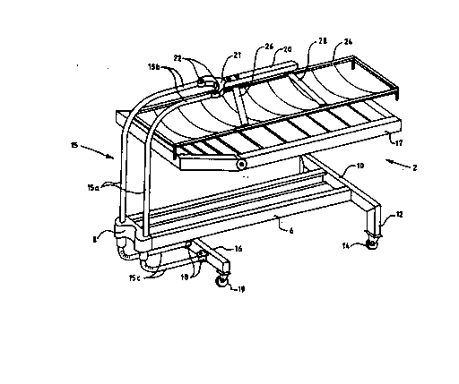
Fig. 2 is a perspective illustration of the bed of Fig. 1
without the lifting means.
Detailed Description of the Preferred Embodiments
The hospital bed 2 lllustrated in the figures comprises a ~;
body 4 which body comprises two longitudinal bars 6 and

WO91/05~32 PCT/~90/~
~ 4 -~
end bars 8 and 10. The end bar 10 at ~he foot end of the
bed is provided with legs 12 and wheels 14. Vertical
portion~ 15a of two bearer rods 15 are disposed turnably
at a distance from each other in the bar 8 at the head end
of the bed. The bearer rods are formed by tubes bent to
form a U and the upper arms 15b of which ~n their initial ~-~
pos~tion, i.e. substantially parallel wlth the longitudinal
axis of the bed, extend to a position over a lying or rest
underlay frame 17 of the bed on which the occupant normally
lies. The lower arms 15c in their initial position extend
for a distance under the body 6. The ends of the lower
arms are connected to each other by a transverse bar 16
via articulated ~oints 18. Wheels 19 are provided at the
ends of the transverse bar. The ends of the upper arms 15b
are connected to each other by a fork portion 21 of a
bearer beam 20 via articulated ~oints 22.
The bed further compr~ses a transfer underlay frame 24
displacing a patient to and from the rest frame 17 and which
in the position illustrated in the figures is supported by
straps 26 and 28 secured to the bearer beam 20 but which in
lts ~nitial position is supported by the lying underlay
frame 17.~
The bearer rods 15 are pivotable about their vertical axes
in parallel direction due to the fact that they have been
connected to each other in the way described above whereby
al~o the bearer beam 20 retains the direction of the bed
when lt is moved sldeways.
When a patient is transferred from the bed onto a transport
underlay or wheeled trolley or stretcher (not shown) beside
the bed the straps 26 and 28 are secured to the transfer
underlay frame 24 disposed under the patient on the lying
underlay frame 17. The lying underlay frame is lowered
down to its bottom position by a lifting device 30 provided
between the lying underlay frame and the body 6 whereby the
transfer underlay frame 24 and the patient on it are

91/05~32 PCT/~gO~00
supported by the bearer beam 20. Subsequent to this, the
bearer rods 15 are turned aside so as to position the
whole transfer underlay frame 24 beside the lying underlay
frame 17 and the transport underlay is lifted to a height
where the patlent and the transfer underlay frame 24 are
s~pported by the transport underlay trolley (not shown)
after which the straps are detached. The transfer of the ~-
patient is safe since while the transfer underlay frame 24
is moved sideways, the~ wheels 19 at the head end of the
bed also move to the same direct~on. Th~s prevents the bed
from toppling over.
The distance of the wheels from the pivot axes of the
b~arer rods is chosen to glve adequate~ support to the
transfer devlce and the body in all stages of the transfer
movement. A prop r dlstance $s 1/8 - 1j3 1 where 1 is
the length of the body. When the patient is brought bac~
to the bed *he lylng underlay frame 17 is lifted to a
higher position to receive the patient carried by the
transfer underlay frame 24.
~ The invention has been described above wlth reference to
- a preferred~applicatlon example but it is clear that the
- ~ - lnventlon can be modifled ln many ways within the scope of
~25 protection defined by the appended pa*ent claims. `
`: ~ . , .'
'';~'
.

Representative Drawing
A single figure which represents the drawing illustrating the invention.
Administrative Status

2024-08-01:As part of the Next Generation Patents (NGP) transition, the Canadian Patents Database (CPD) now contains a more detailed Event History, which replicates the Event Log of our new back-office solution.

Please note that "Inactive:" events refers to events no longer in use in our new back-office solution.

For a clearer understanding of the status of the application/patent presented on this page, the site Disclaimer , as well as the definitions for Patent , Event History , Maintenance Fee  and Payment History  should be consulted.

Event History

Description Date
Inactive: IPC from MCD 2006-03-11
Time Limit for Reversal Expired 1995-04-18
Application Not Reinstated by Deadline 1995-04-18
Inactive: Adhoc Request Documented 1994-10-18
Deemed Abandoned - Failure to Respond to Maintenance Fee Notice 1994-10-18
Request for Examination Requirements Determined Compliant 1992-03-11
All Requirements for Examination Determined Compliant 1992-03-11
Application Published (Open to Public Inspection) 1991-04-20

Abandonment History

Abandonment Date Reason Reinstatement Date
1994-10-18

Maintenance Fee

The last payment was received on 

Note : If the full payment has not been received on or before the date indicated, a further fee may be required which may be one of the following

  • the reinstatement fee;
  • the late payment fee; or
  • additional fee to reverse deemed expiry.

Please refer to the CIPO Patent Fees web page to see all current fee amounts.

Fee History

Fee Type Anniversary Year Due Date Paid Date
MF (application, 2nd anniv.) - standard 02 1992-10-19
Owners on Record

Note: Records showing the ownership history in alphabetical order.

Current Owners on Record
AHLSTROM (A.) CORPORATION
Past Owners on Record
KARI OLKKONEN
MATTI O. NIEMINEN
Past Owners that do not appear in the "Owners on Record" listing will appear in other documentation within the application.
Documents

To view selected files, please enter reCAPTCHA code :


To view images, click a link in the Document Description column. To download the documents, select one or more checkboxes in the first column and then click the "Download Selected in PDF format (Zip Archive)" or the "Download Selected as Single PDF" button.

List of published and non-published patent-specific documents on the CPD .

If you have any difficulty accessing content, you can call the Client Service Centre at 1-866-997-1936 or send them an e-mail at CIPO Client Service Centre.


Document
Description 
Date
(yyyy-mm-dd) 
Number of pages   Size of Image (KB) 
Abstract 1991-04-20 1 76
Claims 1991-04-20 1 55
Cover Page 1991-04-20 1 19
Drawings 1991-04-20 2 56
Descriptions 1991-04-20 5 257
Representative drawing 1999-01-04 1 21
Fees 1993-10-04 1 36
Fees 1992-10-02 1 30
International preliminary examination report 1992-03-11 12 312
Prosecution correspondence 1992-03-11 1 27
Prosecution correspondence 1993-04-05 1 29
PCT Correspondence 1992-06-11 1 32
Examiner Requisition 1993-03-22 1 53
Courtesy - Office Letter 1992-10-30 1 50
Courtesy - Office Letter 1992-05-12 1 30
Courtesy - Office Letter 1992-11-02 1 41