Sélection de la langue

Search

Sommaire du brevet 2065838 

Énoncé de désistement de responsabilité concernant l'information provenant de tiers

Une partie des informations de ce site Web a été fournie par des sources externes. Le gouvernement du Canada n'assume aucune responsabilité concernant la précision, l'actualité ou la fiabilité des informations fournies par les sources externes. Les utilisateurs qui désirent employer cette information devraient consulter directement la source des informations. Le contenu fourni par les sources externes n'est pas assujetti aux exigences sur les langues officielles, la protection des renseignements personnels et l'accessibilité.

Disponibilité de l'Abrégé et des Revendications

L'apparition de différences dans le texte et l'image des Revendications et de l'Abrégé dépend du moment auquel le document est publié. Les textes des Revendications et de l'Abrégé sont affichés :

  • lorsque la demande peut être examinée par le public;
  • lorsque le brevet est émis (délivrance).
(12) Demande de brevet: (11) CA 2065838
(54) Titre français: LIT D'HOPITAL
(54) Titre anglais: HOSPITAL BED
Statut: Réputée abandonnée et au-delà du délai pour le rétablissement - en attente de la réponse à l’avis de communication rejetée
Données bibliographiques
(51) Classification internationale des brevets (CIB):
  • A61G 7/14 (2006.01)
  • A61G 7/10 (2006.01)
(72) Inventeurs :
  • NIEMINEN, MATTI O. (Finlande)
  • OLKKONEN, KARI (Finlande)
(73) Titulaires :
  • AHLSTROM (A.) CORPORATION
(71) Demandeurs :
(74) Agent: GOWLING WLG (CANADA) LLP
(74) Co-agent:
(45) Délivré:
(86) Date de dépôt PCT: 1990-10-18
(87) Mise à la disponibilité du public: 1991-04-20
Requête d'examen: 1992-03-11
Licence disponible: S.O.
Cédé au domaine public: S.O.
(25) Langue des documents déposés: Anglais

Traité de coopération en matière de brevets (PCT): Oui
(86) Numéro de la demande PCT: PCT/FI1990/000244
(87) Numéro de publication internationale PCT: WO 1991005532
(85) Entrée nationale: 1992-03-11

(30) Données de priorité de la demande:
Numéro de la demande Pays / territoire Date
894970 (Finlande) 1989-10-19

Abrégés

Abrégé anglais

2065838 9105532 PCTABScor01
In a hospital bed comprising a body (4) provided with wheels, a
transfer underlay frame (24) for a patient, a lying or resting
frame (17), which can be lifted and lowered down, lifting means (30)
for the lying frame, and bearer means (15, 20) for a transfer
underlay frame; the bearer means comprise two U-shaped bearer rods
(15) disposed side by side and turnable in the body, the upper
and the lower arms (15b, 15c) of which are interconnected through
articulated joints (18, 22) by a transverse support (16, 21) so as
to secure a parallel turn of the arms aside. A bearer beam (20)
is secured to the upper transverse support (21) and wheels (19)
to the lower support (16). The invention allows a sideways
transfer of a patient on a transfer underlay supported by straps (26,
28) secured to a bearer beam, without changing the direction.
Wheels (19) provided in the bearer rods (15) move simultaneously to
the same direction which ensures that the bed (2) is properly
supported during all stages of the transfer.

Revendications

Note : Les revendications sont présentées dans la langue officielle dans laquelle elles ont été soumises.


WO 91/05532 PCT/FI90/00244
We claim
1. A hospital bed (2) comprising a body (4) provided with
wheels (14, 19), a transfer underlay part (24) for
transferring a patient lying thereon, a resting or lying
underlay part (17) on which a patient normally rests and
which can be raised or lowered, displacing means (30)
for raising or lowering the lying underlay part 17 and
bearer means (15, 20) for supporting the transfer underlay
part, characterized in that
- the bearer means comprise two bearer rods (15)
turnable around their vertical axes and disposed side by
side at a distance from each other in an end (8) of the
body (4), the bearer rods having upper arms (15b) and lower
arms (15c), which upper arms (15b) in their initial position
substantially parallel with the longitudinal axis of the
bed (2) extend for a distance over the lying underlay part
and the lower arms (15c) for a distance under the body 4;
- the upper arms (15b) and the lower arms (15c)
are interconnected by transverse supports (16, 21) via
articulated joints (18, 22) so as to ensure a parallel
displacement of the arms as such are turned aside;
- a bearer beam (20) for the transfer underlay
part 24 is secured to the transverse upper support (21), and
that
- the lower transverse support (16) is provided
with wheels (19).
2. A bed as claimed in claim 1, characterized in that the
bearer rods (15) are made of a tube bent to form a U-
shape.
3. A bed as claimed in claim 1 or 2, characterized in
that the wheels (19) provided in the lower support (16)
are in their initial position spaced at a distance of 1/8
- 1/3 1 from the turning axes of the bearer rods (15)
where 1 is the length of the body (4).

Description

Note : Les descriptions sont présentées dans la langue officielle dans laquelle elles ont été soumises.

WOgl/05532 PCT/~90/00244
2~
HOSPITAL BED
Field of Invention
The present invention relateæ to a hospital bed.
Prlor Art
Swedish published patent application no. 406037 discloses
an apparatus for lifting a patient confined to bed in
which a pulley and a yoke extending over the bed in
transverse direction are prov~ded to serve as transfer
means and are secured to a supporting frame extendin~
above the bed. An underlay for transferring the patient
is connected to bars beside ~he bed and the patient which
bars again are connected to the yoke. By means of the
pulley and the yoke, the patient can be lifted and
transferred lying on the transfer underlay.
Swedish patent specification no. 341787 discloses a device
for lifting a patient in which device a vertical bar serving
as the support frame is connected to an edge of a bed. A
transverse bar extending above the bed is connected to the
- support frame. The structure of the transfer underlay is
rigid and`it is placed under the patient in the bed. Means
for transferrlng a patient comprise a lifting device
connected close to the end of the transverse bar. The
lifting device inc}udes an electric m~tor and a drum
provided with a lifting rope. The transfer means further
comprise a curved frame which is to be placed across over
- the patient and to which the rigid transfer underlay is
connected. The top end of the frame is connected to the
llft~ng rope.
A problem wtth these devices is for example that the
transfer means are located above the bed and the patient in
connection with the support frame. This increases the
stress on the support frame, requires space above the bed
and generally encumbers the use of the device.

WO91/05~32 PCT/~90/OO~W
, , , ~ ,~
2~ 3 2
To overcome these and other drawbacks of this kind of
apparatus, a device disclosed in Finnish patent application
no. 892374 has been developed which comprises an elongated
support frame connected to the bed, a transfer underlay
for the patient and transfer means for transferring a
patient on the transfer underlay supported by the support
frame. According to the prior application, the transfer
means comprise lifting means disposed between the support
frame and the lying plane of the bed in such a way that the
support frame and the lying plane of the bed are
transferable relative to each other substantially in the
vertical direction.
In one embodiment of the prior art apparatus, the support
frame is connected directly to the body of the bed in
which bed the lylng plane can be transferred in vertical
direction relative to the body and as the lifting means
serves the lifting means of ~he lying plane.
The support frame can be turned from the ~nitial position
to devlate from the direction of the longitudinal axis of
the bed to~ a desired angle beside the bed in order to
transfer a patient to a transport underlay.
Another application of the prior apparatus further comprises
an additional support for supporting the support frame
durlng the turning movement. The additional support is
employed to prevent the apparatus and the bed from falling
when the support frame is turned from above the bed to a
position deviating from the longitudinal axis of the bed.
Disclosure of Invention
The obJect of the invention is to provide a hospital bed
which dispences with any additional supporting structures
during transfer of a patient and which still is stable.

WO 91/05~32 r J PCr/FI90/00244 ~ ~
3 2~
Another ob~ect of the invention is to provide a structurally
simple hospital bed.
The hospital bed of the invention i characterized in that
bearer means comprise two bearer rods pivotable about
their vertical axes and disposed side by side at a distance
from each other in an end of the body, the bearer rods
having upper arms and lower arms, which upper arms in
their initial position substantially parallel with the
longitudinal axis of the bed extend to a distance over
lying underlay part and the lower arms to a distance under
the body; in that the upper arms and the lower arms are
interconnected through articulated ~oints by a transverse
support so as to ensure a parallel turn of the arms aside:
in that a bearer beam for a transfer underlay part is
secured to the upper transverse support; and that the
lower support is provided wlth wheels.
The invention provides the advantage that when a patient
i~ being transferred on the transfer underlay from the bed
to a transport underlay beside the bed the transfer underlay
moves in alignment. Less space is thus required beside
the bed than with means in wh~ch the transfer underlay
turns aside.
Brief Description of Drawings
The invention is described in detail, by way of example,
with reference to the accompanyin~ drawings, in which:-
5:
Fig. 1 is a side view of a hospital bed according to thelnvention; and
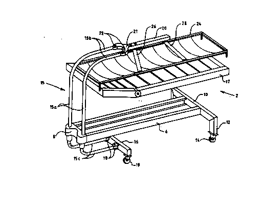
Fig. 2 is a perspective illustration of the bed of Fig. 1
without the lifting means.
Detailed Description of the Preferred Embodiments
The hospital bed 2 lllustrated in the figures comprises a ~;
body 4 which body comprises two longitudinal bars 6 and

WO91/05~32 PCT/~90/~
~ 4 -~
end bars 8 and 10. The end bar 10 at ~he foot end of the
bed is provided with legs 12 and wheels 14. Vertical
portion~ 15a of two bearer rods 15 are disposed turnably
at a distance from each other in the bar 8 at the head end
of the bed. The bearer rods are formed by tubes bent to
form a U and the upper arms 15b of which ~n their initial ~-~
pos~tion, i.e. substantially parallel wlth the longitudinal
axis of the bed, extend to a position over a lying or rest
underlay frame 17 of the bed on which the occupant normally
lies. The lower arms 15c in their initial position extend
for a distance under the body 6. The ends of the lower
arms are connected to each other by a transverse bar 16
via articulated ~oints 18. Wheels 19 are provided at the
ends of the transverse bar. The ends of the upper arms 15b
are connected to each other by a fork portion 21 of a
bearer beam 20 via articulated ~oints 22.
The bed further compr~ses a transfer underlay frame 24
displacing a patient to and from the rest frame 17 and which
in the position illustrated in the figures is supported by
straps 26 and 28 secured to the bearer beam 20 but which in
lts ~nitial position is supported by the lying underlay
frame 17.~
The bearer rods 15 are pivotable about their vertical axes
in parallel direction due to the fact that they have been
connected to each other in the way described above whereby
al~o the bearer beam 20 retains the direction of the bed
when lt is moved sldeways.
When a patient is transferred from the bed onto a transport
underlay or wheeled trolley or stretcher (not shown) beside
the bed the straps 26 and 28 are secured to the transfer
underlay frame 24 disposed under the patient on the lying
underlay frame 17. The lying underlay frame is lowered
down to its bottom position by a lifting device 30 provided
between the lying underlay frame and the body 6 whereby the
transfer underlay frame 24 and the patient on it are

91/05~32 PCT/~gO~00
supported by the bearer beam 20. Subsequent to this, the
bearer rods 15 are turned aside so as to position the
whole transfer underlay frame 24 beside the lying underlay
frame 17 and the transport underlay is lifted to a height
where the patlent and the transfer underlay frame 24 are
s~pported by the transport underlay trolley (not shown)
after which the straps are detached. The transfer of the ~-
patient is safe since while the transfer underlay frame 24
is moved sideways, the~ wheels 19 at the head end of the
bed also move to the same direct~on. Th~s prevents the bed
from toppling over.
The distance of the wheels from the pivot axes of the
b~arer rods is chosen to glve adequate~ support to the
transfer devlce and the body in all stages of the transfer
movement. A prop r dlstance $s 1/8 - 1j3 1 where 1 is
the length of the body. When the patient is brought bac~
to the bed *he lylng underlay frame 17 is lifted to a
higher position to receive the patient carried by the
transfer underlay frame 24.
~ The invention has been described above wlth reference to
- a preferred~applicatlon example but it is clear that the
- ~ - lnventlon can be modifled ln many ways within the scope of
~25 protection defined by the appended pa*ent claims. `
`: ~ . , .'
'';~'
.

Dessin représentatif
Une figure unique qui représente un dessin illustrant l'invention.
États administratifs

2024-08-01 : Dans le cadre de la transition vers les Brevets de nouvelle génération (BNG), la base de données sur les brevets canadiens (BDBC) contient désormais un Historique d'événement plus détaillé, qui reproduit le Journal des événements de notre nouvelle solution interne.

Veuillez noter que les événements débutant par « Inactive : » se réfèrent à des événements qui ne sont plus utilisés dans notre nouvelle solution interne.

Pour une meilleure compréhension de l'état de la demande ou brevet qui figure sur cette page, la rubrique Mise en garde , et les descriptions de Brevet , Historique d'événement , Taxes périodiques et Historique des paiements devraient être consultées.

Historique d'événement

Description Date
Inactive : CIB de MCD 2006-03-11
Le délai pour l'annulation est expiré 1995-04-18
Demande non rétablie avant l'échéance 1995-04-18
Inactive : Demande ad hoc documentée 1994-10-18
Réputée abandonnée - omission de répondre à un avis sur les taxes pour le maintien en état 1994-10-18
Exigences pour une requête d'examen - jugée conforme 1992-03-11
Toutes les exigences pour l'examen - jugée conforme 1992-03-11
Demande publiée (accessible au public) 1991-04-20

Historique d'abandonnement

Date d'abandonnement Raison Date de rétablissement
1994-10-18

Taxes périodiques

Le dernier paiement a été reçu le 

Avis : Si le paiement en totalité n'a pas été reçu au plus tard à la date indiquée, une taxe supplémentaire peut être imposée, soit une des taxes suivantes :

  • taxe de rétablissement ;
  • taxe pour paiement en souffrance ; ou
  • taxe additionnelle pour le renversement d'une péremption réputée.

Veuillez vous référer à la page web des taxes sur les brevets de l'OPIC pour voir tous les montants actuels des taxes.

Historique des taxes

Type de taxes Anniversaire Échéance Date payée
TM (demande, 2e anniv.) - générale 02 1992-10-19
Titulaires au dossier

Les titulaires actuels et antérieures au dossier sont affichés en ordre alphabétique.

Titulaires actuels au dossier
AHLSTROM (A.) CORPORATION
Titulaires antérieures au dossier
KARI OLKKONEN
MATTI O. NIEMINEN
Les propriétaires antérieurs qui ne figurent pas dans la liste des « Propriétaires au dossier » apparaîtront dans d'autres documents au dossier.
Documents

Pour visionner les fichiers sélectionnés, entrer le code reCAPTCHA :


Pour visualiser une image, cliquer sur un lien dans la colonne description du document. Pour télécharger l'image (les images), cliquer l'une ou plusieurs cases à cocher dans la première colonne et ensuite cliquer sur le bouton "Télécharger sélection en format PDF (archive Zip)" ou le bouton "Télécharger sélection (en un fichier PDF fusionné)".

Liste des documents de brevet publiés et non publiés sur la BDBC .

Si vous avez des difficultés à accéder au contenu, veuillez communiquer avec le Centre de services à la clientèle au 1-866-997-1936, ou envoyer un courriel au Centre de service à la clientèle de l'OPIC.


Description du
Document 
Date
(aaaa-mm-jj) 
Nombre de pages   Taille de l'image (Ko) 
Abrégé 1991-04-20 1 76
Revendications 1991-04-20 1 55
Page couverture 1991-04-20 1 19
Dessins 1991-04-20 2 56
Description 1991-04-20 5 257
Dessin représentatif 1999-01-04 1 21
Taxes 1993-10-04 1 36
Taxes 1992-10-02 1 30
Rapport d'examen préliminaire international 1992-03-11 12 312
Correspondance de la poursuite 1992-03-11 1 27
Correspondance de la poursuite 1993-04-05 1 29
Correspondance reliée au PCT 1992-06-11 1 32
Demande de l'examinateur 1993-03-22 1 53
Courtoisie - Lettre du bureau 1992-10-30 1 50
Courtoisie - Lettre du bureau 1992-05-12 1 30
Courtoisie - Lettre du bureau 1992-11-02 1 41