Note: Descriptions are shown in the official language in which they were submitted.
2~a~6
VACUUM-OPERATED V~N~ER DRYER
Background and SummarV of the Invention
This invention relates to a dryer, and more particularly
to a dryer wherein a vacuum or subatmospheric pressure is
established within the dryer, which, together with the application
of heat, produces drying of material handled. The dryer is
particularly suited for the drying of veneer or similar sheet
material which can be prepared as a layered stack within the dryer.
Because the dryer of the invention utilizes a vacuum,
moisture within the material being processed vaporizes at a lower
temperature than in conventional type dryers. As a consequence,
for a given dryer temperature, drying may be performed more rapidly
than with other types of dryers. With a lower temperature used in
drying, resinous materials which vaporize at the higher
temperatures typifying conventional dryers tend not to be vaporized
and expelled into the atmosphere. This substantially minimizes
pollution problems that characterize conventional dryers.
In a dryer constructed pursuant to the invention, a pair
of relatively movable, opposed platens are brought together, and
under the action of vacuum press against opposite sides of the load
handled. These walls are supported by the load, and there is an
absence in the dryer of substantial containment walls that must be
adequately braced to withstand the atmospheric pressure which is
present on the outside of the dryer. The dryer features a novel
construction for sealing one platen against the other, whereby a
vacuum may be established within the dryer. The invention further
embraces, in one modification thereof, the provision of a conveyor
whereby material may be easily transported into and out of the
dryer.
A general object of the invention, therefore, is to
provide an improved dryer for heating material, such as wood
2~&~ 9~
veneer, which relies on the application of heat and also the
establishment of a vacuum to produce the drying action.
Another object is to provide such a dryer which has a
minimal extent of containment walls functioning to define the
limits of a vacuum chamber within the dryer.
Another object is to provide a dryer with improved means
for sealing together relatively movable sections in the dryer.
A dryer constructed according to the invention readily
adapts itself to the handling of loads of different thickness. A
dryer pursuant to the invention may be relatively simply
constructed, and at low cost.
Brief Description of the Drawin~s
These and other objects are attained by the invention
which is described hereinbelow in conjunction with the accompanying
drawings, wherein:
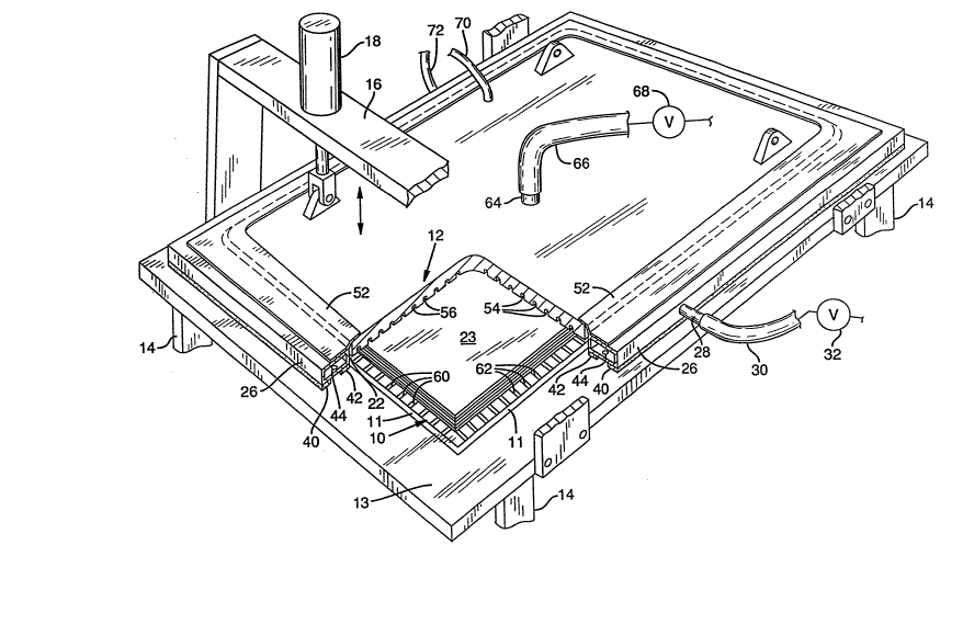
Fig. 1 is a perspective view of a dryer, with portions
broken away;
Fig. 2 is a cross-sectional view, showing a modified form
of a dryer; and
Fig. 3 is a schematic showing details of how a vacuum may
be produced in the dryer.
Detailed Descri~tion of a Preferred Embodiment
A dryer constructed pursuant to the invention may include
a pair of opposed and separable plates or platens, indicated in the
drawings at 10 and 12. Lower platen is suitably connected, through
a ribbon of heat insulating material 11, to a margin plate 13.
Elements 10, 11, and 13 together form one rigid structure. In the
particular form of the invention illustrated, the platens are of
substantially rectangular outline. In details of construction,
however, the platens of different dryers may vary from one dryer
to another.
2 ~ t~ ~ ~
The platens ordinarily are prepared from a heat
conductive material, such as a metal. In the units that I have
made, platens composed of aluminum have performed entirely
satisfactorily.
The lower platen is conveniently supported on a base or
frame, such as is partially illustrated at 14. The upper platen,
as already mentioned, is separable from the lower one. The upper
platen, for convenience, may be hinged or otherwise supported
relative to the lower platen in a removable fashion (to permit
entry to the interior of the dryer). As illustrated in Fig. 1, the
upper platen is movably supported over the lower one on framework
16, with hydraulically actuated rams such as ram 18 providing a
means for adjustably raising and lowering the platen.
During operation of a dryer, a chamber 22 is formed
between the lower surface of the upper platen and the upper surface
of the lower platen, and this chamber receives the material 23 to
be dried, such as a sheet or stack of sheets of veneer. To
establish a sealed relation between the platens, whereby a vacuum
or subatmospheric condition may be established within the dryer
chamber, means is provided extending about the perimeter of a
platen whereby such may be sealed to the platen opposite.
Specifically, and with reference to the dryer shown in
Fig. 1, the seal provided takes the form of an elongate hollow
manifold, shown at 26, extending as a continuous rectangular loop
about the perimeter of upper platen 12. The manifold, which
specifically may take the form of elongate rectangular tubing, is
connectable to a vacuum source, such as a vacuum pump, through
fitting 28, tube 30, and valve 32.
Extending along the base of the manifold is a double seal
construction. This includes one elongate sealing strip 40
extending in a continuous course along the underside of the
~Q~:~s~
manifold, and spaced laterally from this strip, another sealing
strip 42, also extending in such a continuous course. The strips
may be made of foam rubber or either elastomer material. Thus,
they are deformable to provide a tight seal with the platen surface
provided thereunder.
The manifold along its length is provided with apertures
or ports, such as the one shown at 44. These provide fluid
communication between the interior of the manifold and the space
existing being sealing strips 40, 42. The strips form what is
referred to herein as an elongate vacuum mouth. With a
subatmospheric pressure or vacuum established within the manifold,
such vacuum also exists between the sealing strips. Atmospheric
pressure then causes the manifold to be forced downwardly through
the sealing strips against the platen surface thereunder.
Establishing a vacuum within the manifold quickly produces a sealed
relationship between the manifold and the platen thereunder. With
the vacuum broken, release is immediate.
The manifold and associated structure is connected to
adjacent margins of platen 12 through a flexible means permitting
the manifold and platen 12 to have different elevations with
respect to platen 10 beneath it. In this way, different heights
of material may be handled, with a seal still established.
Specifically, shown at 52 is an elongate, flexible, air-
impervious strip, with an inner margin joined and thus sealed to
platen 12, and an outer margin joined and thus sealed to manifold
tube 26. The strip, which may be made of a suitable elastomer
material, is flexible and resilient. This enables the manifold to
have different positions with respect to platen 12.
The face of platen 12 which faces downwardly is formed
with a set of elongate parallel grooves shown at 54 and these
intersect with another set of elongate parallel grooves 56. The
2~3~ ~
grooves thus all interconnect with each other. The grooves provide
an air-passage means extending over the face of the platen
accommodating air movement between regions located interiorly of
the chamber or space 22 and a region located adjacent manifold 26.
When a vacuum is initiated within press chamber 26, this passage
means promotes the movement of air while such is being expelled
from the chamber. Furthermore, the passage means accommodates the
movement of moisture and other gases from the chamber to outside
the dryer during the drying process.
A similar set of grooves, such as those shown at 60 and
62, may be provided in the upper face of the lower platen 10 with
such grooves performing a similar function.
A hollow fitting 64, tube 66, and valve 68 connecting
with a vacuum source are provided for establishing a vacuum within
the dryer. The fitting has an interior communicating with dryer
chamber 22.
Means is also provided for heating the space within the
dryer. Specifically, shown at 70, 72 are conductors leading to the
upper and lower platens, respectively. These connect with
conventional electrical heating elements embedded within the upper
and lower platens 12, 10.
Because the vacuum within the main drying chamber and
within the sealing means may be separately regulated, the pressure
within the drying chamber may be set at the level determined to be
the optimum for the amount of moisture handled, etc. The vacuum
within the mouth of the sealing means is adjusted to produce the
seal required with this being the main purpose of this vacuum.
Fig. 3 illustrates schematically how a vacuum may be
produced within the vacuum chamber and how moisture removed from
the chamber may be condensed. Thus, the tube 66 leads to a heat
exchanger 82. A vacuum source 84 connects with the heat exchanger
2 ~
and is opexable to produce a vacuum within the exchanger and tube
30. Moisture condensed within the heat exchanger flows by gravity
downwardly from the exchanger to be collected in a collection tank
86~
In Fig. 2, there are illustrated portions of a modified
form of a dryer. In the dryer of Fig. 2, a seal is provided
between upper platen 90 and lower platen 92, by an elongate
continuous length of tubing 94, which may have flexible walls and
may resemble, for instance, a continuous length of hose. The
interior of this tubing is connected, through a fitting 96, with
a source of air under pressure. Air under pressure is introduced
to the interior of the hose to extend the hose whereby such
throughout its length projects to the extent permitted by the
construction of the hose downwardly from the bottom surface of
platen 90. With the upper platen drawn downwardly toward the lower
platen, by esta~lishing a vacuum within the dryer, the hose is
pressed against the surface beneath it to establish a seal.
In the modification shown in Fig. 2, a run 98 of an
elongate continuous conveyor belt is shown. This belt has its
lower surface slidably supported on the top of platen 92. The
conveyor belt enables material to be conveyed into the interior of
the dryer without handling of the operator.
In using the belt, atmospheric pressure is established
within the dryer. This enables upper platen 90 to be lifted
upwardly from conveyor belt run 98. The conveyor belt is moved to
transport the load that was in the dryer to a region that is
outside the dryer and to replace this load with another load
supported on the conveyor run. With this other load properly
positioned between the two platens, belt movement i5 stopped. The
upper platen then is lowered toward the lower one to place hose or
tubing 94 against the top of the conveyor belt. A vacuum may then
2 ~ 9 ~
be reestablished within the dryer chamber.
While various modifications of the invention have been
described, obviously, further modifications and variations are
possible without departing from the invention. It is desired to
cover all such modifications and variations that come within the
scope of the invention.