Language selection

Search

Patent 2066166 Summary

Third-party information liability

Some of the information on this Web page has been provided by external sources. The Government of Canada is not responsible for the accuracy, reliability or currency of the information supplied by external sources. Users wishing to rely upon this information should consult directly with the source of the information. Content provided by external sources is not subject to official languages, privacy and accessibility requirements.

Claims and Abstract availability

Any discrepancies in the text and image of the Claims and Abstract are due to differing posting times. Text of the Claims and Abstract are posted:

  • At the time the application is open to public inspection;
  • At the time of issue of the patent (grant).
(12) Patent Application: (11) CA 2066166
(54) English Title: ELECTRICAL CONNECTOR ARRANGEMENT FOR MAINS CONNECTION
(54) French Title: CONNECTEUR ELECTRIQUE
Status: Dead
Bibliographic Data
(51) International Patent Classification (IPC):
  • H01R 13/514 (2006.01)
  • H01R 13/447 (2006.01)
  • H01R 13/713 (2006.01)
  • H01R 25/00 (2006.01)
  • H01R 25/16 (2006.01)
(72) Inventors :
  • SCHMID, RUDOLF (Switzerland)
(73) Owners :
  • SCHMID, RUDOLF (Not Available)
(71) Applicants :
(74) Agent: MARKS & CLERK
(74) Associate agent:
(45) Issued:
(86) PCT Filing Date: 1991-08-12
(87) Open to Public Inspection: 1992-02-15
Availability of licence: N/A
(25) Language of filing: English

Patent Cooperation Treaty (PCT): Yes
(86) PCT Filing Number: PCT/CH1991/000169
(87) International Publication Number: WO1992/003857
(85) National Entry: 1992-03-31

(30) Application Priority Data:
Application No. Country/Territory Date
2641/90-0 Switzerland 1990-08-14

Abstracts

English Abstract


ABSTRACT OF THE DISCLOSURE

The electrical connector arrangement for mains
connection is distinguished by modular releasable and
conductively interconnectable connector units (7, 8, 19).


Claims

Note: Claims are shown in the official language in which they were submitted.


- 8 -

THE EMBODIMENTS OF THE INVENTION IN WHICH AN EXCLUSIVE
PROPERTY OR PRIVILEGE IS CLAIMED ARE DEFINED AS FOLLOWS:

1. An electric circuit arrangement for mains connection,
characterised by modules, detachable circuit construc-
tion units that are current-conductive and connectable
to one another (1 to 20).


2. The electric circuit arrangement as defined in claim 1
wherein at least one circuit construction unit (1,2,7)
is constructed for a mains socket connection having a
plug cord (1';2) or as a plug (7).


3. The electric circuit arrangement as defined in claims 1
and 2 wherein the current-conducting connecting means
of the circuit construction units (4-6 and 10-13)
simultaneously form interlocking means (4'-6' and
10'-13').


4. The electric circuit arrangement as defined in claims 1
and 2 wherein the circuit construction units (14-17)
comprise in addition interlocking means (14'-17').


5. The electric circuit arrangement as defined in claim 1
wherein the circuit construction units (1-20) are
constructed cubical or quarter-shaped and have


- 9 -

connecting means on at least two sides.

6. The electric circuit arrangement as defined in claim 5
wherein the circuit construction units (20) are close-
able on the connecting-means side by means of small
contact-protecting plates (20').


7. The electric circuit arrangement as defined in one or
several of the aforementioned claims 1 - 6 wherein the
circuit construction units are constructed as, among
other things, an on-off switch or a power circuit-
breaker (1), as a transit block or preferably a switch-
able transformer (2), as an individual socket (3), as a
plug switch (7), as a multiple-socket strip or board
(8), as a dimming switch (19), as a switching-on lag
switch or potentiometer or connecting piece or branching
or the like (not shown).


8. The electric circuit arrangement as defined in claim 3
wherein the current-conducting connecting means are flat
or round plug pins and plug sockets (3',4',6' or 5') or
turning-lock contact means (10',11',12') or slot contact
means (13').


- 10 -

9. The electric circuit arrangement as defined in claim 4
wherein the additional locking means are screw
connections (14',15') or swivel means (16') or locking
slide means (17').

Description

Note: Descriptions are shown in the official language in which they were submitted.


:
:
- 1 -901_41


Rudolf Schmid Fallanden/Switzerland


Electric Circuit Arrangement
for Mains Connection


The present invention relates to an electric circuit
arrangement for mains connection.


In many industrial and domestic fields, the need for a
versatile mains connection technique increases in order that
not only many consumers may be connected to an existing
mains socket, but also that low-voltage apparatus may be

connected and switching means interconnected.


Existing connection strips provided with a plug cord cannot
fulfil these demands, even if these connection means are
provided with an on-off switch and in most cases comprise
several sockets.


2 ~ 6 ~


~her0fore, a primary object of the present invention is to
create an electric circuit arrangement for mains connection
which meets practically all requirements in regard to
possible connection, transformation and switching
techniques.


This is achieved according to the invention in the first
place by modules, detachable circuit construction units that
are current-conductive and connectable to one another.


In this connection, it is of advantage that at least one
circuit construction unit is constructed for a mains socket
connection having a plug cord or as a plug.


Further, in order to make the circuit arrangement childproof
or safe against mechanical stress, it is of advantage that
the current-conducting connecting means of the circuit
construction units simultaneously fo~m interlocking means;
and/or that the circuit construction units comprise in
addition interlocking means.


For an optimum handiness, it is further of advantage that
the circuit construction units are constructed cubical or
quarter-shaped and have connecting means on at least two
sides.


2Q~166


For a current-contact protection, the circuit construction
units can, moreover, be closeable on the connecting-means
side by means of small contact-protecting plates.


In order to attain a wide range of applications, it is
essential to the invention that the circuit construction
units are constructed as, among other things, an on-off
switch or a power circuit-breaker, as a transit block or
preferably a switchable transformer, as an individual
socket, as a plug switch, as a multiple-socket strip or
board, as a dimming switch, as a switching-on lag switch
or potentiometer or connecting piece or branching or the
like.


Further, according to the invention, the current-conducting
connecting means can ~e flat or round plug pins and plug
sockets or turning-lock contact means or slot contact means;
and, furthermore, the additional locking means can be screw
connections or swivel means or locking slide means.


Exemplary embodiments of the invention will now be more
particularly described with reference to the accompanying
drawings in which:


2~6~6~


FIG. 1 a,b is a diagrammatic representation of a first
modular circuit construction unit shown in two
elevations;


FIG. 2 a,b is a diagrammatic representation of another
modular circuit construction unit shown in two
elevations;


FIG. 3 is a diagrammatic trans~erse section of a
circuit construction unit shown as a modular
individual socket;


FIG. 4 a,b,c, is a diagrammatic representation of other
specific embodiments of modular circuit
construction units;


FIG. 5 is a diagrammatic representation of a modular
circuit construction unit comprising small
. contact-protecting plates;


FIG. 6 is a diagrammatic representation of modular
circuit construction units in the form of
connecting pieces or branchings;


FIG. 7 a - g is a diagrammatic representation of modular


circuit construction units with different
contact connecting means; and


IG. 8 a - d is a diagrammatic representation of modular
circuit construction units with different
interlocking means.


As the representations of the drawings show, the electric
circuit arrangement for mains connection distinguishes
itself according to the invention by modules, detachable
circuit construction units that are current-conductive and
connectable to one another 1 - 20.


As FIGS. 1,2 and 4a show, at least one circuit construction
unit 1,2,7 is constructed for a mains socket connection
having a plug cord 1'j2 or as a plug 7.


As FIGS. 1 to 6 show in particular, the circuit construction
units can be constructed as, among other things, an on-off
switch or a power circuit-breaker 1, as a transit block or
preferably a switchable transformer 2, as an individual

socket 3, as a plug switch 7, as a multiple-socket strip or
board 8, as a dimming switch 19, as a switching-on lag
switch or potentiometer or connecting piece or branching or
the like (not shown).


2~6~


Of course, other circuit elements in addition to those here
are, moreover, capable of being developed and adapted as
modular circuit construction units.


In order to make a circuit arrangement consisting of a
plurality of such circuit construction units as previously
described safe against mechanical stress or childproof, the
current-conducting connecting means of the circuit
construction units can simultaneously form interlocking
means 4' - 6' or 10' - 13' according to FIG. 7 a-g.


Further, the circuit construction units can, of course, also
comprise additional locking means 14' - 17', as Figures 8
a - d illustrate. In which case, these interlocking means
can be screw connections 14', 15' or hinge means 16' or
locking slide means 17'.


For an optimum handiness, it is further of advantage that
the circuit construction units are constructed cubical or
quarter-shaped and have connecting means on at least two
sides (all Figures).


For a current-contact protection, the circuit construction
units 20 are, moreover, closeable on the connecting-means
side by means of small contact-protecting plates 20', as


2~6~ 6~


FIG. 5 illustrates in particular.


As FIGS 3 and 7 show in particular, the current-conducting
connecting means can be flat or round plug pins and plug
sockets 3',4',6' and 5' or turning-lock contact means 10',
11',12' or slot contact means 13'.


Thus from the aforementioned there results a modular
electric circuit arrangement for mains connection for a
practically unlimited applicability.


Naturally, in this connection, there are no limits to a
further development, so far as the other specific embodi-
ments are based on the modular circuit construction units
according to the invention.
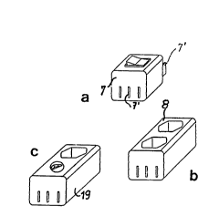

Representative Drawing
A single figure which represents the drawing illustrating the invention.
Administrative Status

For a clearer understanding of the status of the application/patent presented on this page, the site Disclaimer , as well as the definitions for Patent , Administrative Status , Maintenance Fee  and Payment History  should be consulted.

Administrative Status

Title Date
Forecasted Issue Date Unavailable
(86) PCT Filing Date 1991-08-12
(87) PCT Publication Date 1992-02-15
(85) National Entry 1992-03-31
Dead Application 1996-02-12

Abandonment History

There is no abandonment history.

Payment History

Fee Type Anniversary Year Due Date Amount Paid Paid Date
Application Fee $0.00 1992-03-31
Maintenance Fee - Application - New Act 2 1993-08-12 $50.00 1993-07-23
Maintenance Fee - Application - New Act 3 1994-08-12 $50.00 1994-08-02
Owners on Record

Note: Records showing the ownership history in alphabetical order.

Current Owners on Record
SCHMID, RUDOLF
Past Owners on Record
None
Past Owners that do not appear in the "Owners on Record" listing will appear in other documentation within the application.
Documents

To view selected files, please enter reCAPTCHA code :


To view images, click a link in the Document Description column. To download the documents, select one or more checkboxes in the first column and then click the "Download Selected in PDF format (Zip Archive)" or the "Download Selected as Single PDF" button.

List of published and non-published patent-specific documents on the CPD .

If you have any difficulty accessing content, you can call the Client Service Centre at 1-866-997-1936 or send them an e-mail at CIPO Client Service Centre.


Document
Description 
Date
(yyyy-mm-dd) 
Number of pages   Size of Image (KB) 
International Preliminary Examination Report 1992-03-31 19 473
Drawings 1992-02-15 2 45
Claims 1992-02-15 3 55
Abstract 1992-02-15 1 6
Cover Page 1992-02-15 1 14
Representative Drawing 1999-08-23 1 4
Description 1992-02-15 7 157
Fees 1994-08-02 1 48
Fees 1993-07-23 1 22