Note: Descriptions are shown in the official language in which they were submitted.
2û6~92
FMC 0241 PUS
90-350
IMPROVED METHOD FOR FABRICATING
A CLUTCH CYLINDER-DRUM ASSEMBLY
Technical Field
This invention relates generally to a method
for fabricating clutch cylinder-drum assemblies for
vehicle drivetrains, and in particular, to an improved
method using resistance or laser beam weld techniques
to join a clutch cylinder to a drum.
Backqround Art
10 Conventionally, two methods of manufacturing
have been employed to fabricate clutch cylinder-drum
assemblies for use in automatic transmissions or
transaxles of vehicle drivetrains. The first utilizes
an electron beam weld method and the second involves
integrally casting the assembly and machining it to a
desired configuration. Each method has disadvantages
and limitations.
The electron beam method is applied to a
clutch cylinder and drum, each of which is generally
formed through a stamping operation. The clutch
cylinder includes an annular, radially extending base
plate connected to an axially extending cylindrical
member. The drum includes an annular, radially
extending end plate adjoining an axially extending
cylindrical wall. The clutch cylinder is placed
within the drum, with the base plate abutting the end
plate. An electron beam is directed to tXe inside of
the clutch cylinder with the beam penetrating through
the base and end plates. Alternativel~, the electron
beam is applied to the exterior of the end plate,
penetrating into and through the end and base plates.
.. . . . . ..
2~6~92
FMC 0241 PUS -2-
90-350
Generally, due to the size and complexity of the
electron beam welding apparatus, the components to be
welded are rotated about a fixed welding apparatus to
form an annular weld.
One disadvantage of this m~thod is that
electron beam welding typically requires a great deal
of maintenance to keep the welding apparatus operating
properly. Electron beam welding generally requires a
vacuum chamber which reduces barometric pressure to
the order of 1 x I0~1 to 1 x I0-2 Torr. (Atmospheric
pressure is approximately 760 Torr). If air or other
gases are present, the electron beam will scatter,
thus deteriorating the effectiveness of the weld
procedure. This high vacuum tends to draw metal
vapors from workpieces, thereby requiring removal of
these vapors. The voltage used across the workpieces
is in the range of 30,000 - 200,000 volts, thus
requiring an expensive power supply.
Second, the electron beam methods known to
have been used to date have penetrated the inner or
exposed surface of the annular base plate of the
clutch cylinder. This produces warping, and weld
spatter on this surface. Unless weld spatter is
removed, at a later date it may break free and
contaminate the transmission fluid. In turn, this may
cause clogging in the flow of transmission fluid or a
valve body located in the transmission or transaxle
system. Further, these contaminants may inc~ease wear
to parts within the transmission or transaxle.
The warping of the exposed inner surface of
the clutch cylinder may cause further problems. If
the surface is not flat, a piston operating within the
clutch cylinder may become ramped or cocked, allowing
for fluid leakage or piston interference and seizure
during operation of the transmission or transaxle. As
2066292
FMC 0241 PUS -3-
90-350
other components of the transmission or transaxle
often locate in relation to this surface, flatness of
the exposed surface is required for their proper
positioning. Consequently, an additional
manufacturing step may be required to machine this
surface to achieve a desired flatness.
Finally, the electron beam weld method uses
X-ray radiation. This is potentially dangerous to
operators, and, therefore, lead shielding or heavy
sections of machine base castings are required around
the welding apparatus. Shielding makes observation of
the welding process more difficult, and interferes
with steps involved in correcting problems associated
with the welding apparatus and procedure. Also, in
some States, official certification and inspections
are required to operate an electron beam welder.
The second conventional method of
manufacturing a clutch cylinder-drum assembly involves
forming the assembly directly in cast iron and
machining it to the proper configuration. This method
also has a number of drawbacks.
First, cast iron is a more expensive
material than the metal typically used to produce the
stamped metal components. Second, facility and
tooling costs are also greater. Cast iron requires a
mold, is difficult to machine and in some instances,
residue and chips remain after machining. These
pieces may break free and contaminate the transmission
fluid, thereby causing wear and clogging problems as
discussed above. Finally, cast iron clutch cylinder-
drum assemblies generally are significan~ly heavier
than are those made of stamped metal components.
Methods for joining annular components
together are known. One example is Nakayama et al,
U.S. Pat. No. 3~949,186, which discloses a method
2~6292
FMC 0241 PUS -4-
90-350
using laser beam, electron beam or plasma welding
techniques to join precision-machined hollow bodies to
other metallic members. A concentrated beam of heat-
producing energy is directed across and peripherally
about the axially extending interface of the bodies to
be joined. This reference suggests using the method
for adjoining concentric precision machined wave
guides for propagation of electromagnetic radiation.
Disclosure Of The Invention
10 The present invention includes a method for
fabricating a clutch cylinder-drum assembly for use in
vehicle drivetrains wherein the interior surface of a
clutch cylinder remains free of weld spatter. The
clutch cylinder is placed within a drum, with a base
plate on the clutch cylinder being iuxtaposed with an
end plate on the drum. Either a resistance or a laser
weld technique is used to form a weld connection
between interfacing surfaces of the end and base
plates wherein the weld connection does not penetrate
the interior surface of the clutch cylinder.
Therefore, additional manufacturing steps to remove
weld spatter or other weld material from this surface,
or to machine the surface flat, are minimized.
The resistance and laser weld techniques are
used to join the clutch cylinder to the drum without
using a vacuum chamber. Also, these techniques do not
produce X-ray radiation, unlike electron beam welding,
and therefore avoid radiation-related safety risks.
A particular advantage of the resistance
weld technique is that no rotating parts are necessary
to form the weld connection. In contrast, other
welding techniques require that either the apparatus
206~ 2
FMC 0241 PUS -5-
90-350
for welding, or the components to be welded, be
rotated relative one another to form an annular weld.
The resistance weld technique usually requires less
time as the entire weld connection is formed
simultaneously. Therefore, more clutch cylinder-drum
assemblies may be fabricated in a given time period.
Also, fewer sets of welding apparatus are required to
fabricate a particular number of the assemblies in a
given time. This is an important consideration when
high volume production is required.
An object of the present invention is to
overcome the disadvantages and problems encountered
with prior methods of fabricating clutch cylinder-drum
assemblies for vehicle drivetrains.
In particular, it is an object to provide a
lower maintenance and more cost-effective method than
is available by other methods of clutch cylinder-drum
fabrication now in use.
Another object is to provide a method of
fabrication of a clutch cylinder-drum assembly in
which the inner, exposed surface of the clutch
cylinder remains free of weld material and other loose
particulates that otherwise might be produced during
fabrication.
Yet another object is to a provide a method
of fabrication wherein no X-ray radiation is produced
and no lead shielding is needed.
Still another object is to provide a method
of fabrication which does not require rotation between
the welding apparatus and the components being welded
and accordingly, which requires less time to form a
complete weld connection.
Other objects, features and advantages will
become more readily apparent from the following
description and the accompanying drawings.
2066292
FMC 0241 PUS -6-
90-350
Brief Description Of Drawings
Figure 1 is a perspective view of a drum
with an annular projection located on an interfacing
surface of an end plate;
Figure 2 is a perspective view of a drum
with a clutch cylinder located therein;
Figure 3 is a sectional view taken along
planes co-linear with line 3-3 of Figure 2 showing the
clutch cylinder secured within the drum;
Figure 4 is an enlarged fragmentary
sectional view of the area 4 of Figure 3 showing the
clutch cylinder juxtaposed with the drum before
resistance welding;
Figure 4A is an enlarged fragmentary
sectional view, similar to Figure 4, of the clutch
cylinder-drum assembly following resistance welding;
Figure 4B is a further enlarged fragmentary
sectional view of area 4B in Figure 4A showing further
details of a weld connection;
Figure 5 is an enlarged fragmentary
sectional view, similar to Figure 4, showing the
clutch cylinder juxtaposed within the drum prior to
laser welding;
Figure 5A is an enlarged fragmentary
sectional view, similar to that of Figure 5, showing
the clutch cylinder secured to the drum through a weld
connection which is formed by laser welding;
Figure 6 is a graph illustrative of welding
currents as a function of time during the resistance
weld method; and
Figure 7 is a graph illustrative of closure
forces applied across the drum and clutch cylinder as
a function of time during the resistance weld method.
206~2~2
FMC 0241 PUS -7-
90~350
Best Modes For Carrying Out The Invention
The present invention includes a method for
fabricating a clutch cylinder-drum assembly for use in
an automatic transmission or transaxle of a vehicle
drivetrain wherein the radially extending, inner
exposed surface of the clutch cylinder remains free of
weld spatter.
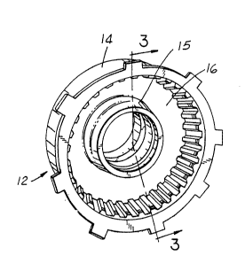
Figures 1-3 show a clutch cylinder-drum
assembly 12 which includes a drum 14 and a clutch
cylinder 16 joined by a weld connection 18.
Generally, a hub 15, as shown in Figure 1, is welded
to drum 14 prior to the addition of the clutch
cylinder 16. Weld connection 18 is preferably formed
by using either a resistance weld or laser beam weld
technique. The drum 14 and the clutch cylinder 16 are
each formed in a stamping operation. One preferred
material is 1006 aluminum killed, draw quality, low
carbon, cold rolled steel. Alternate materials
include steel with up to .44% carbon and high
strength, low alloy steels.
When using the resistance weld techni~ue,
the configuration of drum 14 is slightly different
from the drum 14' which is used with the laser beam
technique (Figure 5). The resistance weld (Figure 4)
calls for the drum 14 to include an annular end plate
20 connected to an axially extending cylindrical wall
22. End plate 20 has radially extending interfacing
and exposed surfaces 24 and 26, with exposed surface
26 being on the axially exterior side of the drum 14.
Interfacing surface 24 has an annular axially inwardly
protruding or extending projection 28 and a pair of
annular grooves 30 radially spaced apart therefrom.
The projection 28 overlies a channel 32 defined in the
associated exposed surface 26, the channel 32
2066292
FMC 0241 PUS -8-
90-350
extending toward the projection 28. Preferably, the
operation that creates projection 28 simultaneously
forms channel 32.
In the preferred embodiment, the end plate
5 20 is about .170" thick. Projection 28 is
approximately .040" high and has a radius of curvature
of about .100"! with its apex located radially about
2.30" from the axial centerline of clutch cylinder-
drum assembly 12. Grooves 30 are about .015" deep and
10 have a radius of curvature of abou~ .030". Channel 32
is approximately .050" deep.
Clutch cylinder 16 has an annular base plate
34 connected to an axially extending cylindrical
member 36. Base plate 34 has radially extending,
15 associated interfacing and exposed surfaces 38 and 40.
Base plate 34 has a thickness of approximately .100".
Exposed surface 40 is generally planar before and
after being subjected to the weld method discussed
herein and may be used as a datum from which other
20 components of the transmission or transaxle may be
located.
This invention also contemplates placing a
projection on the interfacing surface 38 or having
mating projections on both of the interfacing surfaces
25 24 and 38. Accordingly, grooves and channels,
respectively, may also be located on the interfacing
and exposed surfaces of the base plate. Further, the
projections could be intermittent, rather than forming
a continuous annular projection, when hermetically
30 sealing welds are not required. ~
Generally, the clutch cylinder 16 is placed
within drum 14, so that the interfacing surfaces 38
and 24 of the base and end plates 34 and 20 are
juxtaposed. There exists about a .010" annular gap
35 between cylindrical wall 22 and cylindrical member 36.
2066292
FMC 0241 PUS -9-
90-350
A closure force is applied across the base and end
plates 34 and 20 so that they are urged into adjoining
relationship. Then a means for welding is provided
whereby weld connection 18 is formed between the base
and end plates 34 and 20 without the weld connection
18 penetrating the exposed surface 40 of the base
plate 34 so that the exposed surface 40 thereof
remains free of weld spatter.
More specifically, clutch cylinder 16 is
placed concentrically within drum 14 with interfacing
surface 38 of base plate 34 juxtaposed and opposing
the interfacing surface 24 of the end plate 20. The
annular gap between cylindrical wall 22 and
cylindrical member 36 prevents electrical current from
passing thereacross. See Figures 2 and 4. Annular
outer and inner electrodes 42 and 44, having flat
annular surfaces sized generally to mate with exposed
surfaces 26 and 40, are placed against these surfaces.
Portions of outer and inner electrodes 42 and 44 are
shown schematically in Figure 4.
An illustrative weld schedule using the
resistance weld technique for creating weld connection
18 for a drum and clutch cylinder with the dimensions
described above, is shown below in Table 1 and
graphically in Figures 6 and 7.
TABLE 1
~ELD SCHEDULE FOR RES~STANCE ~ELD METHOD
Temiodsn 0-30 ¦ 30-82 ¦ 82-86 ¦86-180 ¦180-19? 192-222 ¦ 222-232 ¦
_ _ _ .
Current in
Kiloamperes O 332 O 370 370 O O
Closure 0-24 ¦ 24 ¦ 24 ¦24 ¦40 !40-0
One Period = 1/60 second
2~66~92
FMC 0241 PUS -10-
90-350
Figure 6 shows the current, i.e.
histogram 46, applied across electrodes 42 and 44, and
accordingly, projection 28 and opposing interfacing
surface 38 during the resistance weld procedure. A
closure force is maintained across electrodes 42 and
44 and the interfacing surfaces 24 and 38 to apply
pressure upon projection 28. Figure 7 shows the
closure force, curve 48, applied across the electrodes
42 and 44 during the resistance welding technique.
The horizontal axis in Figures 6-7 shows time in
periods wherein each period is equal to 1/60 second.
To practice the invention over periods 30-
82, a preheat current of about 332 kiloamperes is
applied in 6 preheating pulses. Each pulse comprises
the current being "on" for 7 periods and then "off"
for 2 periods. Between periods 82 and 86, the current
is off. A welding current of about 370 kiloamperes,
covering time periods 86-192, is then applied for a
total of 12 pulses. Again, each pulse consists of 7
periods of the current being "on" and 2 periods of
the current being "off".
The closure force is increased from 0 to
about 24,000 pounds over the first 30 periods. The
closure force is maintained at that level for the next
150 periods, then increased to about 40,000 pounds for
42 periods and finally reduced to zero over the next
10 periods.
The preheat of about 52 periods warms
projection 28. The current is then turned off for 4
periods to allow for heat distribution throughout
projection 28. The welding current of about 370
kiloamperes is applied for approximate~y 108 periods,
during which time the weld connection 18-is formed.
The closure force is increased from 24,000 pounds up
to 40,000 pounds to ensure that the projection 28 is
2~66292
FMC 0241 PUS -11-
90-350
flattened, such that there is face-to-face contact
between the interfacing surfaces 24 and 38, as shown
in Figures 4A and 4B. The closure force is maintained
for 30 periods after the current is removed to allow
weld connection 18 to cool under pressure. The entire
welding process takes less than 240 periods, or 4
seconds.
The combination of heat and pressure creates
weld connection 18 and results in the projection 28
being flattened, with a portion of its material
flowing into either of grooves 30 located on the
interfacing surface 24. The remainder of the material
from projection 28 is pressed and flows into channel
32 on exposed surface 26. Weld connection 18 forms an
hermetic seal between the interfacing surfaces 24 and
38. Preferably, the exposed surface 40 has contours
which are substantially unchanged before and after the
formation of weld connection 18. As seen in Figures 4
and 4A, the exposed surface 40 retains its original
relatively flat condition as it abuts against the flat
surface of inner electrode 44 throughout the formation
of weld connection 18.
The general shape of the heat-affected zone
of weld connection 18, as it appears when sectioned,
is shown as the outer dashed outline in Figure 4B.
The inner solid line indicates the weld fusion zone as
confirmed by metallographic viewing. Weld connection
18 is similar to a forge weld in that it is formed
with heat and pressure and without a significant
portion of the projection material going into a molten
state. If insufficient heat is provided during the
welding, weld connection 18 may not properly form.
Conversely, too rapid of heating may cause projection
28 to melt and expel weld spatter between the
interfacing surfaces 24 and 38 or else projection 28
20~292
FMC 0241 PUS -12-
90-350
may penetrate exposed surface 40 and generate weld
~ spatter.
A second variation of this method utilizes a
laser beam weld instead of the resistance weld.
Again, no weld spatter remains in the interior of the
clutch cylinder 16 after welding. Many of the
problems associated with the electron beam or casting
methods of producing the clutch cylinder-drum assembly
12 are overcome.
In Figure 5, clutch cylinder-drum assembly
12' comprises a drum 14' and clutch cylinder 16.
Clutch cylinder 16 is identical to that described
above when utilizing the resistance weld technique.
Drum 14', however, has a flat interfacing surface 24'
rather than a projection 28 and grooves 30 as used
with resistance weld technique. Channel 32' is used
to reduce the distance a laser beam 50 must penetrate
before reaching the base plate 34 of clutch cylinder
16. Channel 32' is again approximately .050" deep.
Clutch cylinder 16 is placed concentrically
within drum 14'. Again, an approximate .010" annular
gap exists between cylindrical wall 22' and
cylindrical member 36. A closure force of about 4000
lbs is then applied across the drum 14' and clutch
cylinder 16 with interfacing surface 24' being
juxtaposed with interfacing surface 38. A laser beam
50 is applied to channel 32', penetrating through the
end plate 20' and partially into base plate 34. The
drum 14' and clutch cylinder 16 are rotated relative
to laser beam 50 such that an annular weld connection
18' is formed, thereby fabricating clutch cylinder-
drum assembly 12'. A shielded gas, preferably helium,
is used in conjunction with the laser weld to minimize
the oxides formed in the weld connection 18'. The
weld connection 18' hermetically seals interfacing
2~6~92
FMC 0241 PUS -13-
90-350
surfaces 24' and 38, thereby preventing leakage of
transmission fluid. Again, the exposed surface 40 of
base plate 34 remains free of distortion, weld
spatter, and weld material.
For a drum 14' and a clutch cylinder 16 of
the dimensions and configurations described above,
i.e. having the same size as in the resistance method,
but without the projection 28 and the grooves 30 the
laser beam weld is performed with about 5,000-6,000
watts of power at 25-30 amperes of current, at a feed
rate of 60-70"/min., using a shielding Helium gas
flowing at about 20 ft3/hr, which produces a resultant
weld connection 18'. Figure 5A illustrates weld
connection 18' connecting drum 14' and clutch cylinder
16.
Welds of different sizes, used to join
clutch cylinders and drums different in size and
configuration from that described above, will require
weld parameters, i.e. weld schedules, projection,
groove and channel sizes, differing from those
described above with respect to using the resistance
and laser weld techniques. The above specific
description of the method of fabricating a clutch
cylinder-drum assembly using either a resistance or a
laser weld technique, is intended to be illustrative
and not restrictive.
While in the foregoing specification this
invention has been described in relation to certain
preferred parameters thereof, and many details have
been set forth for purposes of illustration, it will
be apparent to those s~illed in the art that the
invention is susceptible to alteration,and that
certain other details described herein can vary
considerably without departing from the basic
principles of the invention.