Note: Descriptions are shown in the official language in which they were submitted.
2Q663~10
LATCH BEARING FOR BLOW-MOLDED CASE, AND
METHOD AND APPARATUS FOR FORMING SAME
Field of the Invention
This invention relates to cases and similar
articles that are blow-molded from thermoplastic material
and include relatively movable base and cover components
that are releasably secured together by one or more latch
assemblies. The invention more specifically relates to
an improved bearing for a latch assembly of the aforesaid
type, and to a method and apparatus for forming the
bearing and case.
Background of the Invention
The latch assemblies of blow-molded plastic
cases customarily each include a preformed latch member
which is secured adjacent one end to one of the base and
cover components of the case, and that has a latch
element adjacent its opposite end which is movable into
and out of latching engagement with a lug or other
retaining element upon the other one of the case compo-
nents. The latch member's capability for movement
between latched and unlatched positions has heretofore
been realized in one of two different ways. One of
these, disclosed in U.S. Patent 3,828,969, is to employ
a flexible latch member that bends so as to permit
movement of its free end between latched and unlatched
,.
~,
2 2066300
positions. An alternative technique disclosed in U.S.
Patent 4,522,312 employs a substantially rigid latch
member having a pivot element that is snapped into a
discontinuous or "split" bearing of the case.
The prior art latch assemblies of both of the
aforesaid types have significant disadvantages. The
flexible latch members do not provide a solid "feel", and
also tend to automatically reassume their "latched"
positions, when released. This can be quite annoying,
particularly when the case has a plurality of latches
that must all be held in their disengaged positions
before the case can be opened. The rigid latch members
unfortunately can be "snapped" out of, as well as into,
their associated split bearings. A substantial number of
cases having snap-in latch members are returned by
retailers each year to case manufacturers due to loss of
their latch members from the cases. Additionally, the
cost of manufacturing cases with latch assemblies of
either of the foregoing types is increased due to the
need for a separate latch-attaching operation subsequent
to blow-molding of the cases.
Summary of the Invention
The latch assembly of the present invention is free
from the disadvantages and deficiencies of the above-
discussed prior art ones now employed in association withblow-molded plastic cases.
According to an aspect of the present invention is a
latch assembly for a case blow-molded from thermoplastic
material, the case having relatively movable base and
cover components, each of which includes a main body,
which comprises a latch member having a pivot element
adjacent a first end thereof and a latch element adjacent
a second end thereof; a latch bearing integral with one
of the case components, the bearing being formed
substantially simultaneously with and of the same plastic
material as the main body of the one of the case
components, the latch bearing encircling the pivot
2066300
2a
element of the latch member and supporting the latch
member for pivotal movement between a latched position
and an unlatched position; and a keeper element upon the
other of the case components, the keeper element
cooperating at desired times with the latch member to
secure the components of the case together.
The invention further provides a method for
effecting pivotal mounting of the latch, and for
preventing formation of a permanent bond between its
pivot element and
201~63~0
the bearing member. In another of its aspects, the
invention provides apparatus for positioning the pre-
ferred latch member at a desired location within a mold
during molding of the latch bearing member and the main
body of the case component supporting the bearing. In
addition to other functions, the apparatus preferably
causes relative pivotal movement to occur between the
bearing member and the pivot element of the latch member
while the thermoplastic material of the bearing member is
still in a heated condition. Preferably the aforesaid
pivotal movement transpires automatically in response to
opening of the mold within which the case component and
the bearing are formed.
DescriPtion of the Drawings
Other features of the invention will be appar-
ent from the following description of preferred embodi-
ments thereof, which should be read in conjunction with
the accompanying drawings, in which:
FIG. 1 is a fragmentary view of the upper
portion of an upright double-wall, blow-molded case
having relatively movable base and cover components, and
latch assemblies for releasably maintaining such compo-
nents in a closed condition;
FIG. 2 is an enlarged vertical section taken
substantially along the line and in the direction of the
arrows 2-2 of Fig. 1 through one of the latch assemblies
and adjacent walls of the case of Fig. l;
FIG. 3 is an enlarged perspective view of the
latch member used in the latch assemblies;
FIG. 4 is an exploded and rotated perspective
view of fragmentary confronting areas of relatively
movable cavity and core sections of a split mold for
forming a latch bearing member integrally and substan-
tially simultaneously with one of the base/cover compo-
nents of the case; and of a fixture for positioning a
preformed latch member at a desired location within the
2~63~0
mold during molding of the case component and of the
bearing member;
FIG. 5 is a view similar to that of the
leftward part of Fig. 4, but showing the latch and
fixture members in the positions which they occupy during
a molding operation;
FIG. 6 is a vertical sectional view taken
substantially along the line and in the direction of the
arrow 6-6 of Fig. 5;
10FIG. 7 is a vertical sectional view taken
substantially along the line and in the direction of the
arrows 7-7 of Fig. 6;
FIG. 8 is a vertical section taken substantial-
ly along the lines and in the direction of the arrows 8-8
of Fig. 7;
FIG. 9 is a vertical section taken substantial-
ly along the line and in the direction of the arrows 9-9
of Fig. 7;
FIG. 10 is a vertical section taken substan-
tially along the line and in the direction of the arrows10-10 of Fig. 9;
FIG. 11 is a sectional view showing in phantom
lines the position occupied by the latch during the
molding operation, and showing by solid lines movement
undergone by the latch member as the mold opens following
the molding operation;
FIG. 12 is a side elevational view of an
alternative embodiment wherein a robotic apparatus
positions the latch members within the mold;
30FIG. 13 is a view similar to Fig. 5 but showing
an alternative construction of the latch biasing member;
FIG. 14 is a view similar to Fig. 6 but showing
the alternative latch biasing member; and
FIG. 15 is a fragmentary rear perspective view
of the central portion of the alternative latch biasing
member.
2û6~330
Description of the Preferred Embodiments
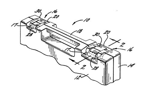
The numeral 10 in Fig. 1 designates a double-
wall case blow-molded from suitable thermoplastic materi-
al, such as polyethylene. Case 10 has complementary base
and cover components 12, 14 that are pivotally or other-
wise movable relative to each other between a closed
position, shown in Fig. 1 and wherein confronting upper
portions of components 12, 14 abut each other; and an
open position (not shown) wherein such portions are
spaced from each other.
Case components 12, 14 are releasably main-
tained in their closed position by at least one, and
illustratively two, latch assemblies 16 located upon the
upper (as viewed in Figs. 1 and 2) walls 17 of case 10
adjacent opposite ends of an optional carrying handle 18.
Each latch assembly 16 includes a substantially rigid
latch member 20, best shown in Fig. 3 of the drawings.
Latch member 20 has an elongate shaft-like pivot element
22 adjacent one end thereof, a latch element 24 adjacent
its opposite end, and a pair of laterally spaced opposite
side elements 26 interconnecting pivot and latch elements
22, 24. The latch member preferably and illustratively
has an angular nonplanar shape which enhances its rigidi-
ty and facilitates manipulation of the latch by a person
grasping its latch element 24. Element 24 preferably and
illustratively has a tab element 25 upon the edge thereof
facing pivot element 22.
Each latch assembly 16 also includes a bearing
member 28 that extends upwardly from and is integral with
the upper (as viewed in Figs. 1 and 2) wall 17 of one of
the case components 12, 14, illustratively base component
12; and further includes a latch keeper member 30 that
extends upwardly from and is integral with the adjacent
upper wall 17 of the other case component 14.
The bearing member 28 of each latch assembly
preferably and illustratively encircles the entire
circumference of pivot element 22 of the associated latch
2~6300
member 20, and extends along substantially the entire
length of the pivot element. Bearing member 28 perma-
nently secures pivot element 22 and the rest of latch
member 20 to case component 12 while permitting free
pivotal movement of the latch member between a latched
position and an unlatched position. In the latched
position of member 20, illustrated by solid lines in
Figs. 1 and 2, engagement between latch element 2~ and
latch keeper 30 maintains case 10 closed. When member 20
occupies an unlatched position, such as that illustrated
by phantom lines in Fig. 2, latch element 2~ is out of
engagement with latch keeper 30 and therefore does not
impede "opening" movement of case components 12, 1~ away
from each other.
The bearing member 28 of each latch assembly 16
is formed about pivot element 22 of the latch member 20
of the assembly. Member 28 is formed during blow-molding
of the case component 12 with which the bearing member is
illustratively associated, and of the same thermoplastic
material as is used for the formation of the main body of
case component 12. Fig. ~ of the drawings shows con-
fronting portions of the cavity and core sections 32, 3~
of a mold 35 that has been modified so as to produce the
foregoing results. Core section 32 has a seat 36 that
receives the preformed latch member 20, and maintains it
in a desired position during the molding operation. Seat
36 has sloping bottom walls 38, opposite side walls 40,
a sloping rear wall ~2, and a sloping (as shown) or
horizontal entry wall ~. A pad ~6 projects from the
upper center portion of rear wall ~2. A chamber ~8 below
pad ~6 has opposite side walls 50 that extend forwardly
from rear wall ~2 and upwardly from bottom wall 38, and
has a sloping top wall 52. A recess 5~ within the
chamber's front lower portion opens from the forward and
bottom edge surfaces 55 of the chamber, and is bordered
by forwardly disposed barrier edge surfaces 55. The
front lower portions of the side walls 50 of chamber ~8
20 ~631`)~)
--7--
contain arcuate recesses 56. Channels 58 within opposite
side walls 40 of seat 36 slidably receive the legs 60 of
a generally U-shaped latch biasing member 62. Member 62
is biased toward pad 4C by resiliently extensible and
compressible members 64, which are illustratively coil
springs. One end of each spring 64 engages and is seated
within the associated leg 60 of member 62. The opposite
ends of the springs engage cap elements 66 that are
secured within the forward end portions of channels 58.
Fig. 5 of the drawings shows the position
occupied by latch member 20 after downward movement from
its position of Fig. 4 into a position of seated engage-
ment with seat 36 of cavity mold section 32. Opposite
side elements 26 of latch member 20 closely straddle
opposite sides 50 of chamber 48, and overlie bottom walls
38 and rear wall 42. Pivot element 22 of latch member 20
extends across the front of chamber 48 and its opposite
ends are received within the recesses 56 in the chamber
side walls 50. Latch element 24 of member 20 overlies
pad 46, and is biased into engagement with the pad by
latch biasing member 62 and the therewith associated
biasing springs 64. During movement of latch member 20
into mold seat 36, member 62 is cammed away from pad 46,
against the biasing force of springs 64, to permit
passage of the lower components of latch member 20 by
member 62.
Core half 34 of mold 35 includes a recessed
area 68 which in the closed condition of the mold forms
a forwardly disposed extension of chamber 48 of mold
section 32. Area 68 is bordered by projecting barrier
edges 69 that in the closed condition of mold 35 engage
the forward edge surfaces 55 of chamber 48 and the
thereto adjacent portions of bottom wall 38 of seat 36 of
mold section 32. As shown in Fig. 8 and 9, the resulting
extended chamber 48 contains pivot element 22 of latch
20, and communicates, via its open bottom and as is best
shown in Fig. 6, with the underlying space 70 containing
2~63~0
the heated thermoplastic parison material 72 from which
the body of case section 12 is formed. Although prevent-
ed by abutting edge surfaces 55 and 69 of mold sections
32, 3~ from entering other areas of latch seat 36, the
heated thermoplastic material from space 70 can and does
pass upwardly into the extended chamber ~8, and forms the
bearing 28 which extends completely about pivot element
22 of latch member 20 and along substantially the entire
length of the pivot element. The bearing member 28 is
formed substantially simultaneously with formation of the
adjacent portion of the upper (as viewed in Fig. 1) wall
17 of case section 12, and is integral with such wall
section. The sectional view of Fig. 6 shows bearing 28
immediately following formation of it and the adjacent
part of the body of case component 12. Subsequent to
formation of the foregoing case and bearing components,
and when such components are in a solid but still heated
condition, the cavity and core sections 32, 3~ of mold 35
are moved in a conventional manner away from each other.
During this "opening" movement of the mold the case
component 12 carrying latch bearings 28 and latch members
20 adheres to core section 3~, and moves with it away
from mold cavity section 32. The pivot element 22 of
each latch member 20 moves in substantial unison with
case component 12 away from cavity section 32 of the
mold. However, as shown in Fig. 11 during the initial
part of such movement, the resilient biasing force
imposed upon each latch element 2~ of the latch member,
by the associated biasing member 62, causes a few degrees
of relative pivotal movement to occur between pivot
element 22 and bearing member 28. Such relative movement
prevents or overcomes whatever temporary surface bond
might otherwise form between bearing 28 and pivot element
22 of latch member 20, such that latch member 20 can
undergo unimpeded pivotal movement about an axis extend-
ing through its pivot element 22. To further insure
against a permanent bond being formed when latch member
~ ~b~3~
g
20 is formed of thermoplastic or other heat-sensitive
material, such material of the latch member should
preferably have a melt temperature (or, in the case of a
pre-molded plastic, a heat transition temperature)
greater than the maximum temperature to which it is
exposed during the molding of bearing member 28 and case
component 12.
Following the aforesaid initial pivotal move-
ment that occurs between bearing member 28 and pivot
element 22 of latch 20, the latch member is permitted by
the resilient mounting of member 62 to move in unison
with case component 12 from mold section 32.
Fig. 12 of the drawings illustrates an alterna-
tive embodiment wherein the positioning of each latch
member 20 within mold section 32 is accomplished by means
of a robotic apparatus 74, rather than manually. Appara-
tus 74 includes a base 76 having bearings 78 mounting a
generally horizontally extending threaded shaft member 80
for reversible rotative movement about its central axis
under the impetus of a drive motor 82. Shaft 80 supports
a traveling nut 8~ and rotation of screw 80 imparts
horizontal or X-axis movement to the nut 84 and to a
generally vertically extending piston and cylinder
assembly 86 affixed to it. Assembly 86 imparts con-
trolled upward and downward movement of desired magni-
tudes to a gripper mechanism 88 upon the lower end of the
rod 90 of assembly 86. Gripper mechanism 88 includes a
pair of gripper elements 92, 9~ and a piston and cylinder
assembly 96 for moving the gripper elements horizontally
toward and away from each other. Apparatus 74 also
includes a magazine 98 containing a supply of latch
members 20 and a spring, piston and cylinder assembly or
other mechanism (not shown) for advancing the latch
members sequentially in the direction of the arrow lOo to
a pick-up position adjacent the rightmost end of magazine
98.
20~3~0
--10--
Prior to the commencement of each molding
operation, gripper mechanism 88 is moved downwardly by
piston and cylinder assembly 86, and piston and cylinder
assembly 96 causes gripper elements 92, 9~ to move toward
each other and to grippingly engage the latch element 2~
of the latch member 20 in the pickup position of magazine
98. This is indicated in solid lines in the upper
portion of Fig. 12. Drive motor 82 and screw 80 then
move gripper mechanism 88 and the thereby gripped latch
member 20 horizontally to the right (as viewed in Fig.
12) to a position wherein they overlie the latch seat 36
within cavity section 32 of the mold. Extension of
piston and cylinder assembly 86 then moves mechanism 88
and the gripped latch member 20 vertically downwardly to
their positions illustrated in the lower part of Fig. 12,
and wherein latch member 20 is seated by seat 36 of
cavity mold section 32, and is resiliently retained by
latch biasing member 62. Gripper mechanism 88 may then
release latch member 20 and be moved upwardly by piston
and cylinder 86 to its upper phantom line position, in
readiness for another cycle of operation. Alternatively,
after gripper mechanism 88 has positioned latch member 20
within recess 36 of cavity mold section 32, the gripper
mechanism may remain in its lowermost position and
continue to engage latch member 20 until such time as the
molding operation has been completed and initial relative
movement of cavity and core sections 32, 3~ of mold 35
away from each other has effected the desired limited
pivotal movement between latch element 22 and the encir-
cling bearing member 28. When gripper mechanism 88
performs the foregoing latch retaining function, as well
as its latch member "loading" function, latch biasing
member 62 and its associated springs 64 and caps 66 may
not be needed or employed.
Figs. 13-15 show other embodiments wherein the
springs 6~ associated with member 62 of the Figs. 1-12
embodiments are not needed or employed. Opposite ends of
2Q~6300
the biasing member 62' of Figs. 13-lS are fixedly con-
nected or integral with the side walls ~0 of mold seat
36. The central part of member 62' has a rearwardly
extending pad 100 thereon. In one embodiment member 62'
is made of resiliently flexible metallic or other materi-
al. As a latch member 20 is moved onto seat 36, engage-
ment between pad 100 and the latch member deflects the
central portion of biasing member 62' sufficiently
forwardly as to not impede seating movement of the latch
member. The tendency of the deflected member 62' to
return to its non-deflected position subjects the seated
latch member to a biasing force that performs the same
function as the biasing force generated in the Figs. 1-12
embodiment by springs 6~. The aforesaid function can
also be achieved by use of a rigid member 62' when the
latch member 20 itself is sufficiently resiliently
flexible, since this also will result in imposition of
the desired biasing force upon the latch member, due to
the tendency of its section 2~ to return in a forward
direction after having been deflected rearwardly by
engagement with the pad 100 upon member 62'.
As will be appreciated from the foregoing
description, the present method of pivotally securing a
pivot latch element of a latch member to one of the base
and cover components of the blow-molded thermoplastic
case preferably includes the steps of positioning the
pivot element of the latch member at a selected location
within the mold, utilizing part of the heated thermoplas-
tic material of the parison introduced into the mold to
form the body of the case component and to substantially
simultaneously form an integral bearing member that is
integral with such body, which encircles the pivot
element of the latch member, and permanently secures the
latch member to the body of the case component. The
method preferably further includes preventing formation
of a permanent bond between the pivot element and the
bearing member, by, among other things, effecting rela-
20 ~63 00
tive movement between the bearing member and the pivot
element of the latch member while the thermoplastic
material forming the bearing member is still in heated
condition.
Although latch members 20 and their pivot
elements 22 illustratively have buckle-like and shaft-
like shapes, respectively, they of course might be of
other shapes.
While specific embodiments of the invention
have been shown and described, this was for purposes of
illustration only, and not for purposes of limitation,
the scope of the invention being in accordance with the
following claims.