Note: Descriptions are shown in the official language in which they were submitted.
2~66691
RACE; AND SHELVES ~HEREFOR
The pre3ent invention relates to storage racks, and, in
particular, to a novel arrangement for connecting together
the shelf members of a rack.
S Storage racks are well-known. These racks are used in
warehouses and other places for storing pallets or
packages. The racks are usually made up of frame members,
which are rigidly connected together to form a frame, and
shelf members, wbich are rigidly connected together to form
a shelf, which is then hung on the frame. The shelves may
be hung with the rear and f ront shelf members at the same
height or with the rear 3helf member higher than the front
and may include rollers, 80 that r~r k~g~ can be loaded
onto the rack from the back and can then ride on the
rollers to the f ront of the rack . This latter type of rack
is known as a carton f low rack . Many dif f erent
arrangements are known for connecting together the side and
front shelf members of a rack and for mounting rollers on a
shelf. The successful arrangements all include some type
of locking means 80 that the sides, front, and back of the
shelf are rigidly and securely connected together. The
means for mounting rollers usually require3 that the
rollers be mounted on a track which slides into grooves in
the front and rear shelf members. The rear shelf member
typically has a different ~ 38 s__l.ion from that of the
front shelf member in order to provide room for the roller
tracks to be slid into place. This means that two sets of
tooling must be used and two different-shaped pieces must
be kept in stock, creating greater expense than would be
the case if the front and back were identical.
All of the common locking means for locking t~le shelf
members together require that a separate piece be added to
the members being connected together. For example, the
separate piece may be a bolt which passes through holes in
the members and is tightened in place. The two member3 may
~' *
_ _ _ _ _ _ _ _ _ _ _ _ _ . . . . .
~ 2 20~6691
be fastened together by means of hooks and slots, and then
a separate clip may be added to prevent the hooks from
becoming unhooked. All of these connecting means involve
the use of additional pieces which means greater cost, more
difficult assembly, and the possibility that pieces will be
lost, preventing proper assembly.
SUMMARY OF T8E INVENTION
The present invention provides a rack which has locking
meana integral with the shelf members, 80 no additional
locking member is required.
By uslng an integral locking member, the present
invention provides a construction which is less expensive
to manufacture than the prior art constructions.
The present invention provides a rack construction
which is much simpler to assemble than racks of the prior
art .
The present invention greatly reduces the problem of
lost pieces in racks.
The present invention provides a means for mounting
roller tracks which permits the front and rear shelf
members to be identical. This saves on tooling costs and
on the cost of stocking different parts.
BRIEF DESCRIPTION OF THE DRAWINGS
Figure 1 i8 a perspective view of a rack made in
accordance with the present invention;
Figure 2 is a top view thereof;
Figure 3 is a broken-away side view thereof;
Figure 4 is a side view partially in section of one
shelf on the rack;
Figure 5 is a broken-away exploded perspective view of
the left side shelf member, the back shelf member, and one
of the roller tracks;
Figure 6 is a broken-away, exploded perspective view of
a vertical frame member and clip which support the shelf;
_ _ , , ,,, ,, _,,,,,,,,, , , ,, _ _
3 2066~91
Figure 6A i8 a perspective view of the clip;
Figure 7 ia a 8ide view partially in gection of a lower
portion of the rack, with package8 shown in phantom;
Figure 8 i8 a front view of a roller track which has
5 been removed from its shelf;
Figure 9 i8 a view taken along the ~ection 9-9 of
Figure 8;
Figure 10 is view taken along the line 10-10 of Figure
8;
Figure 10A is a broken-away perspective view of the
portion o the roller track ahown in Figures 9 and 10;
Figure 11 is a front view of the center divider which
has been removed f rom its shelf;
Figure 12 is a broken-away view taken generally along
the section 12-12 of Figure 2, showing the vertical frame
members, the clips, and a 3helf;
Figure 13 i~ a view taken along the section 13-13 of
Figure 2;
Figure 14 is an enlarged, broken-away view of the left
portion of the shelf shown in Figure 13; and
Figure 15 is the same view as Figure 14, with the hook
portion lifted upward to show how it is inserted into the
slot .
DESCRIPTION OF TI~E ~n~ nn~ll EMBODIMENT
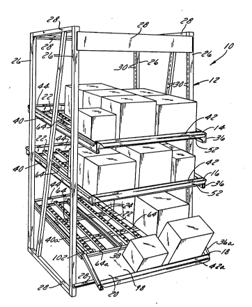
~he rack 10 shown in Figure 1 is made up of a frame 12,
and three shelves 14, 16, and 18. The top shelf 14 and
middle shelf 16 are identical to each other, and the bottom
shelf 18 i9 a little different, in that Lt lncludes a
tilted front portion 20.
Each shelf shown Ln Figure 1 includes a number of
roller tracks 22 with rollers 24 supported on the roller
tracks 22. The rollers 24 permit the packages to move
easily from the back of the shelf to the front of the
shelf. This rack 10 is intended as an example of a typical
arrangement of shelves, but racks could include more or
4 2~6~91
fewer shelves, and each ~helf may or may not include tilted
front portions or rollers.
The rack 10 is made up of vertical frame members 26 and
horizontal frame members 28, which are bolted together or
5 welded together to form a rigid frame. The inside surface
of the vertical frame members 26 has double rows of notchcs
30, which are used to support the shelves.
Figure 6 shows a portion of one of the vertical frame
members 26 and the notches 30 and a clip 32, which has
10 projections 34 that fit into the notches 30 to hold the
clip 32 on the vertical frame member 26. At least four of
auch clips 32 are used to support each shelf. The clips 32
are mounted on the vertical members 26 at the desired
height, and then the shelf simply hooks onto the clips and
15 hangs from the frame 12.
Figure 3 shows a single shelf 14 mounted on the frame
12. The clips 32 cannot be seen in this view, because they
are hidden behind the vertical memoers 26, but it is
obvious from the position of the shelf 14 that the clips 32
20 are mounted on the vertical member~ 26 at different
heights, with the ront clips 32 mounted lower than the
rear clips 32, and the right side beam 36 of the shelf 14
simply hooks over the top of the clips. The left side of
the shelf 14 is mounted in the same way, 80 that the shelf
25 14 is mounted at an i nrl; nr~d angle alpha. Products can be
loaded onto the shelf 14 from the rear and will then roll
down the rollers 24 toward the front of the shelf 14 to be
unloaded. This arrangement of using inclined shelves and
rollers is desirable, because it provides a
30 first-in-fir~t-out arrangement, 80 there is a controlled
turn-over of products.
As can be seen in Figures 2 and 11-13, in the center of
the shelves 14, 16, 18 is a gnide 38, which defines
separate lanes and allows the cartons to f low properly
35 toward the front of the rack. In most installations, a
shelf would be wlder than that shown in these drawings and
, _ _ _ , . _ _ _
.
5 20~691
would have several guides 38 at intervals along lts width.
Each shelf 14, 16 i8 made up of a left beam 40, a right
beam 36, a front beam 42, and rear beam 44. ThQ
cros~-section of the front and rear beams 42, 44 can be
seen in Figure 4. The cross-section of both the front and
rear beams 42, 44 includes a vertical portion 46, an
inwardly-projecting portion 48 at the bottom of the
vertical portion 46, and an upward extension 50 at the end
of the inwardly-projecting portion 48. The cross-section
of the front beam 42a on the bottom shelf 18 is slightly
dLfferent from the front beams 42 of the other shelves 14,
16, in that it does not include the upward extension 50.
At the top of the vertical portion 46 of the front and rear
beams 42, 44 is an outwardly-extending lip 52. The front
and rear beams 42, 44 also include angled slots 54 in their
upward extension portions 50, as shown in Figures 5, 13 and
14, wl-ich are used to secure the roller tracks 22 to the
shelf .
The cross-section of the left and right beams 40, 36 is
shown in Figureg 12-15. Both the left and right beams 40,
36 include a vertical face 56, a downwardly-curved leg 58
at the top of the vertical face 56, and an upwardly-cu,rved
leg 60 at the bottom of the vertical face 56. The
downwardly-curved leg 58 fits over the top of the clip 32
to support the shelf on the frame 12. The upwardly-curved
leg 60 has notches 62 along its top edg~, as ~hown in
Figure 4, and is used to carry intermediate support members
64, which prevent the roller tracks 22 from sagging in the
middle .
The front and rear beams 42, 44 hnve downwardly-hooking
projections 66 extending from their left and right ends,
and the vertical faces 56 of the left and right beams 40,
36 have vertical slots 68, which receive the hooks 66 to
connect the ends of the beams together to form a
rectangular shelf. The beams also include an integral
locking means, which makes the connection between the beams
_ _ _ _,, . . ,,, . , , , =,, ,, ,,, _ ,, , ,, _ _ _ _ _ _ _ , , ,
20~6591
6
more rigid and prevents the hooks from coming out of the
slots. This integral locking means eliminates the need for
a separate locking member as was required in prior art
designs .
The integral locking means ~n~ln~ an integral
vertical flap 70 which lies adjacent to each of the slots
68. The vertical flap 70 has a top edge 72 which is
integral with the vertical face 56 of the left and right
beams 40, 36, and the vertical flap 70 has left, right, and
bottom edges 74, 76, 78, respectively, which are free from
the vertical face 56. The bottom edge 78 of the vertical
flap 70 is cut to form two legs, a shorter leg 80 and a
longer leg 82. The shorter leg 80 is bent inwardly along
the line 79 at a slight angle from the vertical.
Tlle manner in which the vertical flap 70 functions can
be seen best in ~igures 14 and 15. Figure 14 shows that,
when the hook 66 of the rear beam 44 is inserted into the
slot 68 in the left beam 40 until the hook 66 reaches the
bottom of the slot 68, the inwardly-bent portion 79 of the
20 shorter leg 80 of the vertical flap 70 is just above the
inwardly-projecting portion 48 of the rear beam 44. If a
force is applied to the rear beam 44 trying to lift the
rear beam 44 upward relative to the left beam 40, the
shorter leg 80 wiLl contact the inwardly-projecting portion
25 o~ the rear beam 44, preventing the rear beam 44 from
moving up. Since the rear beam 44 must move up relative to
the left beam 40 in order for the hook 66 to be removed
from the slot 68, the shorter leg 80 prevents the rear beam
44 and left beam 40 from being disassembled once they are
30 assembled. This same connecting and locking arrangement i8
used at each corner of the rectangular shelf.
The longer leg 82 extends below the inwardly-projecting
portion 48 of the rear beam 44 and contacts the left end of
the inwardly-projecting portion 48. This prevents the
35 vertical flap 70 from flexing inward.
The rear beam 44 and left beam 40 are connected
7 2~66691
together a~ shown in Figure 15. The downwardly-hooking
projection 66 on the left end of the rear beam 44 i8 moved
toward the left until it enterg the vertical glot 68 on the
left beam 40. Then the rear beam 44 is moved downward. As
5 the rear beam 44 is moved downward relative to the left
beam 40, the inwardly-projecting portion 48 of the rear
beam 44 contacts the inwardly-bent short leg 80 on the
vertical flap 70. The force of the rear beam 44 acting on
the slight angle of the inwardly-bent short leg 80 causes
10 the vertical flap 70 to flex outward, allowing the
inwardly-projecting portion 48 of the rear beam 44 to get
past the short leg 80. When the hook 66 has reached the
bottom of the slot 68, the rear beam 44 has moved down far
enough that it has passed the short leg 80 and no longer
15 pushes the short leg 80 outward. The vertical flap 70 then
returns to its vertical position, with the short leg 80
located directly above the inwardly-projecting portion 48
of the rear beam 44. It is also possible to use a
screwdriver or other tool to push the short leg 80 inwardly
20 even further to provide a more secure locking arrangement.
This connecting and locking arrangement is used at all
four corners of the rectangular shelf until the entire
shelf is assembled.
There is an opening 84 in the vertical flap 70, which
25 can be used for disassembling the shelf. The opening 84
can recsive a screwdriver or other tool which can be used
to pry the vertical flap 70 outward, which permits the rear
beam to move upward past the shorter leg 80, so the rear
beam 44 can be lifted up relative to the left beam, and the
30 hook 66 can be removed from its slot 68.
The mounting arrangement for the rollers 24 i8 aB
follows: The rollers 24 are mounted on axles 86, and the
ends of the axles 86 are mounted in the left and right
rails 88, 90. Upper strips 92 connect the left rail 88 and
35 right rail 90 together, and there are spaces between the
strips 92, through which the tops of the rollers 24
_, , , _ _ . _ _ _ _
8 2066691
project. The rollers 24, rails 88, 90, and strips 92 form
the roller track 22. The cross-section of the rails 88, 90
can be seen in Figure 14. The rails 88, 90 are primarily
vertical but include an angled portion 94 at their bottom
5 edge. This angled portion 94 fits into thc corresponding
angled slots 54 of the upward extension 50 of the front and
rear beams 42, 44 to secure the track 22 to the shelf. It
can be seen in Figures 5, and 8-10 that there are small
discontinuities 96 in the angled cros~-section of the rails
88, 90 near both ends. The discontinuities 96 are formed
by crimping or f lattening the angled portion 94 . These
discontinuitiea 96 eermit the track 22 to be installed
without requiring that it be slid backwards into the rear
frame member 44 and then forward into the front frame
15 member 42, as was required in the prior art design. The
prior method of installation required that the front and
rear beams 42, 44 have different cross-sections so that the
rear beam 44 had enough depth to receive the track as it
was slid backward. This meant that the rear beam and the
20 front beam could not be identical, requiring ~eparate
tooling to produce the front and back beams, and requiring
that two dif f erent beams be stocked. All of this
additional expense and inconvenience is eliminated by the
present design.
In order to install the track on the shelf, the
discontinuities on the front and rear of the track are
aligned with the angled slots 54 on the front and rear
beams, 42, 44, and the rails are pushed downward until the
angled portions 94 of the rails 88, 90 are aligned with the
angled slots 54 in the front and rear beams 42, 44. At
this point, the back end of the track 22 is very close to
the vertical portion 46 of the rear rail 44. Then, the
track is slid forward a short distance, 80 that the angled
portion 94 of the rails 88, 90 enters the angled slots 54
of the front and rear beams 42, 44, and is slid forward a
bit more, until the front end of the track 22 contacts the
_ _ _ . _ _ _ _ _ _
9 2066691
vertical portion 46 of the front beam 42. At this point,
the track 22 is secured on the shelf. The angled slots 54
on the front and rear beams 42, 44 prevent the track from
moving up or down relative to the shelf, and the track iB
5 as far forward as it can go. The only direction the track
22 could move is backward, and, since it i8 inclined
downward from back to front and all the packages move from
back to front, no force is ever applied to the track to
move it in the backward direction. It would be possible to
10 accomplish the same type of installation with
discontinuities 96 only near the rear end of the rails 88,
90, but this would leave a bit larger gap between the back
end of the rails 88, 90 and the vertical portion 46 of the
rear beam 44 after installation of the track.
Tlle guide 38 has the same kind of angled portion 94 as
the roller tracks and mounts onto the angled slots 54 in
the front and rear beams 42, 44 in the same manner as the
roller tracks.
The lowermost shelf 18 is slightly different from the
20 shelves that have already been described, because it has a
tilted front portion 20, which makes it easier for people
working in a warehouse to pick up articles out of the boxes
on the rack. As was mentioned earlier, this type of shelf
could be located ~t any height on the rack and, in fact,
25 all the shelves could be of this type, depending upon the
installation. The left and right side beams 40a, 36a on
the lowest shelf 18 are the same as in the other shelves,
except that they have been formed at an angle. This is
intended to be accomplished by cutting a triangular section
30 out of each side beam, forming the beam, and then welding
the 1. ;n;ng cut edges together. The front and rear beams
42a, 44 connect to the side beams in the same way as on the
other shelves. A special type of intermediate support
member 64a is used in the angled area. This special
35 int~ te support member 64a has slots 99 near both ends
of its web portion 101 which permit it to fit down over the
lO 2066691
upwardly-curved portion 60 of the two side beams 36, 40.
TheYe slot3 99 permit the rear leg 100 of the intermediate
3upport member 64a to ba caught in a notch 62 on each of
the side beams 36a, 40a. The front leg 102 of the special
5 intermediate support member 64a rest8 on the
upwardly-curved side portions 60 of the tilted portion 20.
The intermediate support member 64a has the same angled
slots 54 in its rear leg 100 as do the front and rear beams
42, 44 in the other shelves, and it supports the roller
10 tracks 22 and divider 38 in the same manner as the front
beam 42 on the other shelves. A piece of sheet metal 98 is
bent at ita back edge, which fits cver the front leg 102 of
the special intermediate support 64a. The front edge of
the sheet metal 98 abuta the front beam 42a. This piece of
15 sheet metal aervea as the f loor of the angled portion of
the ahelf.
It will be obvious to thoae skilled in the art that
ation8 may be made to the embodiment described above
wit out departlnq Erom the ~ope o~ the pre ~ent invention.