Language selection

Search

Patent 2066942 Summary

Third-party information liability

Some of the information on this Web page has been provided by external sources. The Government of Canada is not responsible for the accuracy, reliability or currency of the information supplied by external sources. Users wishing to rely upon this information should consult directly with the source of the information. Content provided by external sources is not subject to official languages, privacy and accessibility requirements.

Claims and Abstract availability

Any discrepancies in the text and image of the Claims and Abstract are due to differing posting times. Text of the Claims and Abstract are posted:

  • At the time the application is open to public inspection;
  • At the time of issue of the patent (grant).
(12) Patent: (11) CA 2066942
(54) English Title: VENTING CONSTRUCTION FOR VEHICLE LIGHTING-FIXTURE
(54) French Title: DISPOSITIF D'AERATION POUR APPAREIL D'ECLAIRAGE DE VEHICULE
Status: Deemed expired
Bibliographic Data
(51) International Patent Classification (IPC):
  • F21S 45/30 (2018.01)
  • F21V 29/83 (2015.01)
  • F21V 31/03 (2006.01)
(72) Inventors :
  • KAMISHINA, HIROSHI (Japan)
  • YAMAGUCHI, NORITAKA (Japan)
(73) Owners :
  • STANLEY ELECTRIC CO., LTD. (Japan)
(71) Applicants :
(74) Agent: SMART & BIGGAR LP
(74) Associate agent:
(45) Issued: 1998-11-17
(22) Filed Date: 1992-04-23
(41) Open to Public Inspection: 1992-10-25
Examination requested: 1995-02-21
Availability of licence: N/A
(25) Language of filing: English

Patent Cooperation Treaty (PCT): No

(30) Application Priority Data:
Application No. Country/Territory Date
3-36900 Japan 1991-04-24

Abstracts

English Abstract


A venting construction of a vehicle lighting-fixture
having a housing formed with a venting hole,
characterized in that said venting hole is in the form
of a pipe and extends through the housing, an opening
thereof confronts a wall-like structure within said housing
leaving a suitable spacing, and said structure is provided
with an enclosure for encircling said pipe-like venting
hole leaving a suitable spacing.


French Abstract

Cette invention concerne un moyen de mise à l'air libre d'un appareil d'éclairage de véhicule ayant un corps muni d'un évent en forme de tube qui se prolonge à l'intérieur dudit corps jusqu'à proximité d'une paroi, la distance le séparant de celui-ci étant adaptée à la fonction à assurer. Ladite paroi comporte des projections qui entourent le tube à une distance appropriée.

Claims

Note: Claims are shown in the official language in which they were submitted.

THE EMBODIMENTS OF THE INVENTION IN WHICH AN EXCLUSIVE
PROPERTY OR PRIVILEGE IS CLAIMED ARE DEFINED AS FOLLOWS:


1. A vehicle lighting-fixture having a housing formed with a venting
structure including a venting hole, wherein:
said venting hole is in the form of a pipe means which extends
through said housing for passing venting air into the interior of said housing;
said pipe means having an opening on an interior portion of said
housing that confronts a solid wall-like structure within said housing, said solid
wall-like structure facing said opening with a spacing therebetween; and
said venting structure further comprising an enclosure extending from
said solid wall-like structure in an interior portion of said housing, said enclosure
encircling at least a portion of said pipe means with a lateral opening
therebetween, and said enclosure having an opening portion in direct
communication with the interior of said housing.


2. The ventilating construction according to Claim 1, wherein said
structure comprises the back of a reflecting mirror.


3. The ventilating construction according to Claim 1, wherein said
structure comprises an escutcheon provided in the peripheral edge of the
reflecting mirror.


- 6 -


Description

Note: Descriptions are shown in the official language in which they were submitted.


20669q2

SPECIFICATION


TITLE OF THE INVENTION
VENTING CONSTRUCTION FOR VEHICLE LIGHTING-FIXTURE
BACKGROUND OF THE INVENTION
Field of the Invention
The present invention relates to a vehicle lighting-
fixture SL~il as a headlamp, and more specifically to a
construction of a venting hole provided in a housing of
a vehicle lighting-fixture.
Description of the Prior Art
Fig. 3 shows an example of a conventional venting
hole of this kind. In order to provide a permeability
within a chamber formed by a housing 11 and a lens 12
of a headlamp 10, a pipe-like venting hole 91 is projected
externally of the housing ll. A rubber pipe 92 or the
like is connected to the venting hole 91 to prevent entry
of a drop of water.
The headlamp 10 encases therein a structure for
example such as a reflecting mirror 13 which constitutes
the headlamp 10.
However, in the aforementioned conventional venting
hole 91, the rubber pipe 92 is connected thereto to thereby
surely prevent an entry of a drop of water but dust
floating in air is sucked thereinto as it is. With the
passage of using time of the headlamp 10, dusts are


~ 0 6 6 Q 4 2
,~
is accumulated on a reflecting mirror 13 and the like. As a result, there gives rise
to a problem of insufficient illuminance.
SUMMARY OF THE INVENTION
The present invention provides a vehicle lighting-fixture having a
housing formed with a venting structure including a venting hole, wherein: said
venting hole is in the form of a pipe means which extends through said housing for
passing venting air into the interior of said housing; said pipe means having an
opening on an interior portion of said housing that confronts a solid wall-like
structure within said housing, said solid wall-like structure facing said opening with
10 a spacing therebetween; and said venting structure further comprising an
enclosure extending from said solid wall-like structure in an interior portion of said
housing, said enclosure encircling at least a portion of said pipe means with a
lateral opening therebetween, and said enclosure having an opening portion in
direct communication with the interior of said housing.
BRIEF DESCRIPTION OF THE DRAWINGS
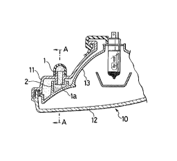
Fig. 1 is a sectional view showing one embodiment of a venting
construction for a vehicle lighting-fixture according to the present invention.
Fig. 2 is a sectional view taken on line A-A of Fig. 1.
Fig. 3 is a sectional view showing a conventional example.
DETAILED DESCRIPTION OF THE PREFERRED EMBODIMENTS
The present invention will be described in detail on the basis of one
embodiment shown in the drawings.


B
24700-22

20669~2


For better understanding, the same parts as those
of prior art are indicated by the same reference numerals,
and the duplicate portions are partly omitted from its
description.
In Fig. 1, a reference numeral 10 designates a
headlamp. In this headlamp 10, a chamber is formed by
a housing 11 and a lens 12, and a venting hole 1 is
pr~vided o~the side o th~ ihGusing il to provide ventilation
for the chamber, similar to the prior art. According
to the present invention, the venting hole 1 is in the
form of a pipe and extends through the housing 11.
The venting hole 1 according to the present
invention will be further described. This venting hole
1 is formed so as to extend through from outside toward
the interior of the housing 11, that is, so that the
venting hole 1 projects into both inside and outside of
the housing 1. The venting hole 1 is bored so that
particularly an inner end la thereof confronts a wall-
like structure for example such as the back of a reflecting
mirror 13 provided within the chamber leaving a suitable
spacing.
At the same time, from the side of the reflecting
mirror 13 is provided a ring-like enclosure 2 so as to
surround the venting hole 1 leaving a suitable spacing.
Thereby, air attracted through the venting hole 1 impinges
upon the reflecting mirror 13, after which moving direction


20669~2


direction thereof is inverted so that air is scattered
into the chamber through and between the outer diameter
of the venting hole 1 and the enclosure 2.
The function and effect of the venting construction
according to the present invention constructed as described
above will be described. With the aforementioned arrange-
ment, air containing dust sucked from the venting hole
1 imping~s upca the refl~cLi..~ mirror 13, and temporarily
loses its flow velocity, after which the direction thereof
is inverted.
This means that the dust contained in air is
precipitated, or adhered to or separated when it impinges
upon the back of the reflecting mirror 13. As a result,
dust contained in air is decreased.
While in the above-description, the structure has
been explained by way of the back of the reflecting mirror
13 as an example, it is to be noted that the structure
is not limited to the reflecting mirror 13 but others
for example such as an escutcheon provided in the peripheral
edge of the reflecting mirror can be freely selected.
As described above, according to the present
invention, there is provided a venting construction for
a vehicle lighting-fixture wherein a venting hole is inthe
form of a pipe and extends through a housing, an opening
thereof confronts a wall-like structure within the housing
leaving a suitable spacing, and the structure is provided


20669~2


with an enclosure for encircling the pipe-like venting
hole leaving a suitable spacing. With this arrangement,
air containing dust sucked into the chamber is once
permitted to impinge upon the structure, and the dust
is adhered to or precipitated and then separated so that
the dust is not scattered into the chamber, thus reducing
the amount of adherence of dust to the reflecting mirror
or the lik~-.o p~e~enl ~Lhe 'owering of illuminance and
to extend the service life of the vehicle lighting-fixture.


Representative Drawing
A single figure which represents the drawing illustrating the invention.
Administrative Status

For a clearer understanding of the status of the application/patent presented on this page, the site Disclaimer , as well as the definitions for Patent , Administrative Status , Maintenance Fee  and Payment History  should be consulted.

Administrative Status

Title Date
Forecasted Issue Date 1998-11-17
(22) Filed 1992-04-23
(41) Open to Public Inspection 1992-10-25
Examination Requested 1995-02-21
(45) Issued 1998-11-17
Deemed Expired 2002-04-23

Abandonment History

There is no abandonment history.

Payment History

Fee Type Anniversary Year Due Date Amount Paid Paid Date
Application Fee $0.00 1992-04-23
Registration of a document - section 124 $0.00 1992-12-01
Maintenance Fee - Application - New Act 2 1994-04-25 $100.00 1994-02-25
Maintenance Fee - Application - New Act 3 1995-04-24 $100.00 1995-03-17
Maintenance Fee - Application - New Act 4 1996-04-23 $100.00 1996-03-14
Maintenance Fee - Application - New Act 5 1997-04-23 $150.00 1997-03-20
Maintenance Fee - Application - New Act 6 1998-04-23 $150.00 1998-03-26
Final Fee $300.00 1998-06-30
Maintenance Fee - Patent - New Act 7 1999-04-23 $150.00 1999-04-14
Maintenance Fee - Patent - New Act 8 2000-04-24 $150.00 2000-03-22
Owners on Record

Note: Records showing the ownership history in alphabetical order.

Current Owners on Record
STANLEY ELECTRIC CO., LTD.
Past Owners on Record
KAMISHINA, HIROSHI
YAMAGUCHI, NORITAKA
Past Owners that do not appear in the "Owners on Record" listing will appear in other documentation within the application.
Documents

To view selected files, please enter reCAPTCHA code :


To view images, click a link in the Document Description column. To download the documents, select one or more checkboxes in the first column and then click the "Download Selected in PDF format (Zip Archive)" or the "Download Selected as Single PDF" button.

List of published and non-published patent-specific documents on the CPD .

If you have any difficulty accessing content, you can call the Client Service Centre at 1-866-997-1936 or send them an e-mail at CIPO Client Service Centre.


Document
Description 
Date
(yyyy-mm-dd) 
Number of pages   Size of Image (KB) 
Representative Drawing 1998-10-26 1 7
Claims 1994-02-27 1 19
Drawings 1994-02-27 1 27
Cover Page 1998-10-26 1 36
Cover Page 1994-02-27 1 15
Abstract 1994-02-27 1 11
Description 1994-02-27 5 129
Description 1998-02-11 5 137
Claims 1998-02-11 1 31
Correspondence 1998-06-30 1 42
Fees 2000-03-22 1 39
Fees 1997-03-20 1 47
Fees 1996-03-14 1 32
Fees 1995-03-17 1 39
Fees 1994-02-25 1 26
Prosecution Correspondence 1992-04-23 4 98
Office Letter 1995-03-20 1 22
Prosecution Correspondence 1997-11-07 2 62
Examiner Requisition 1997-05-09 2 68
Prosecution Correspondence 1995-02-21 1 41
Prosecution Correspondence 1995-02-21 1 36