Note: Descriptions are shown in the official language in which they were submitted.
~'~'O 91/05676 PCT/US90/05856
1
RETRACTABLE SUSPENSION
This invention relates to a retractable
suspension for the wheels of a vehicle and in
particular to a vehicle having a retractable suspension.
The invention will be described by way of
example with reference to the vehicle being a towable
vehicle such as a trailer or the like. It should be
understood that this is by way of example only and that
the invention is not limited to such vehicles.
Known trailers typically have a chassis
terminating at a drawbar assembly or the like one end
thereof, a body mounted on the chassis and wheels
secured to the chassis via suspension components. The
body has a load receiving surface or bed and in use,
that bed, when the drawbar assembly is secured to a
towing vehicle, is spaced from the ground by a
predetermined distance.
It is often difficult to load such a trailer
because the bed is above ground level.
Numerous earlier proposals have been suggested
for providing a trailer or vehicle with a bed which can
be moved relative to the ground such that the bed may
be moved between a raised towing position and a lowered
loading position. With such proposals the disadvantage
referred to above existing in known trailers was
eliminated.
U.S. patent specification 2,230,014 discloses a
WO 91/05676 PCT/US90/05856
2
trailer having a bed which could be raised or lowered
with respect to the ground. The trailer had a
generally U-shaped chassis when viewed in plan and the
bed was coupled thereto by two boomerang shaped
linkages. These linkages occur at longitudinally
spaced positions along the chassis and are linked so
that both of them could be moved by an hydraulic
cylinder to raise and lower the bed. U.S. patent
specifications 2,934,228 and 3,468,440 disclose similar
arrangements.
The diffuculty with such earlier proposals was
that they could not be readily adapted for vehicles
other than trailers. In addition, the arrangements
tended to be complex in construction.
U.K. patent specification 1,124,791 disclosed a
retractable suspension for the wheels of a vehicle and
in particular for towable vehicles such as trailers.
This specification disclosed a trailer having tandem
pairs of wheels. Each wheel was mounted to a free end
of a wheel arm and the other end of the wheel arm was
pivotally mounted to the vehicle chassis. A damper or
suspension cylinder extended between that part of the
arm to which the wheel is mounted and a lever. One end
of the lever was pivotally mounted to the chassis
adjacent the mount for the wheel arm and the other end
of the lever had an hydraulic cylinder coupled to it.
The cylinder joins the levers associated with a pair of
wheels and extension of the cylinder caused the wheel
WO 91/05676 PCT/US90/05856
3
arms to pivot to enable the bed of the vehicle to be
lowered relative to the ground.
This U.K. specification disclosed a second
embodiment where the lever referred to above was
replaced by a leaf spring assembly. In both
embodiments, one of the wheel arms formed a leading
wheel arm and the other a trailing wheel arm.
Because the wheel arms were trailing and
leading wheel arms the arrangement of the U.K. patent
specification could not readily be adapted to operate
with a vehicle having three pairs of wheels. In
addition, the arrangement was such that extension of
the cylinder caused the bed of the vehicle to move
relative to the ground under the influence of gravity.
Retraction of the cylinder effected lowering of the
suspension and hence raising of the vehicle bed.
During raising and lowering the wheel arms and levers
were relatively unsupported.
It is an object of the present invention to at
least minimize the disadvantages referred to above.
According to one aspect, the present invention
provides a vehicle including at least one pair of
wheels, a respective wheel support arm associated with
each said wheel for supporting the wheel for rotation,
one end of said arm being pivotally coupled to the
vehicle, a respective suspension component secured to
the arm and a mounting on the vehicle and having a
distal end, a respective support strut having one end
WO 91/05676 PCT/US90/05856
4
secured to the distal end of the suspension component
and a respective guide member for receiving the distal
end and the one end of the strut and guiding the one
end of the strut and the distal end for movement
therealong when the vehicle is moved between a
travelling position and a loading position.
In the travelling position the suspension
components and wheels are lowered and therefore a load
carrying bed of the vehicle is raised. In the loading
position the suspension components and wheels are
raised and the bed may then be adjacent the ground or
surface along which the vehicle normally travels.
The suspension component is preferably a
spring. In a particularly preferred form of the
invention the spring is a leaf spring assembly having a
plurality of leaves.
The spring assembly may have a saddle member
secured to it between its ends and this saddle member
may facilitate attachment to the wheel support arm.
Attachment of the spring assembly to the arm may be at
or adjacent the wheel carried by the arm.
An attachment member may attach the spring
assembly to the arm for pivotal movement at least
relative to the attachment member but preferably the
attachment member also is free to pivot relative to the
arm. The attachment member may be a relatively short
link member. Preferably the attachment member is a
WO 91/05676 PCT/US90/05856
shackle pivotally attached to and extending between the
saddle member and the arm.
The guide member is preferably an elongate
guide member. The guide member in one embodiment is
5 channel shaped. Preferably the guide member is
substantially C shaped and its free edges may have
short inwardly directed return flanges. The guide
channel in use may extend generally vertically aligned
and may form part of a vehicle frame or body. The
guide channel, when the vehicle is in a travelling
position may receive the strut between its return
flanges.
the channel. may be adapted to provide for
relatively frictionless guiding of the distal end of
the spring assembly as the vehicle is moved between its
travelling and loading positions. Friction resisting
material may line the channel. Friction resisting
strips may extend along opposed interior walls of the
channel. Preferably, friction resisting blocks line
the channel. Alternatively, the distal end of the
spring assembly and/or the one end of the strut have
slide blocks secured to them. The friction resisting
material or blocks may be made of nylon or other
suitable material.
Preferably a seal is provided between the
channel and the strut such that contaminants are
prevented from entering the channel when the vehicle is
WO 91/05676 PCT/US90/05856
6
in the travelling position. Sealing strips may be
positioned on those faces of the return flanges
directed towards the strut.
The end of the spring assembly secured to the
vehicle may be pivotally secured thereto. The end may
be directly secured to the vehicle. Preferably an
attachment member is employed. The attachment member
may directly attach the end of the spring assembly to
the vehicle in the case of a vehicle with independent
multiple wheel pairs. Alternatively, where the vehicle
has load sharing tandem wheel pairs the attachment
member may attach the end of the spring assembly to a
load sharing arm. The attachment member may be a short
link. Preferably the attachment member may comprise a
shackle. The shackle is preferably pivotally secured
to the vehicle or the load sharing arm (as the case may
be) and more preferably is also pivotally secured to
the end of the spring assembly.
The strut may be an elongate member. In one
embodiment the strut is substantially T shaped in
transverse cross section and may be made from two angle
shaped elongate members arranged back to back. The T
shaped strut, in use is positioned so that the
oppositely directed flanges are adjacent the return
flanges of the support channel (when the vehicle is in
the travelling position) and the intermediate flange
projects into the support channel. The one end of the
WO 91/05676 PCT/US90/05856
7
strut may have an attachment portion facilitating its
attachment to the distal end of the spring assembly.
The attachment portion is preferably forked and the
distal end is received by the forked end of the strut.
The attachment portion may be provided by two outwardly
directed plates secured to opposed sides of the
intermediate flange of the strut. As mentioned, the
one end of the strut may carry a slide block. the
slide block may be secured to the outwardly directed
plates which provide the forked attachment portion to
which the distal end of the spring assembly is secured.
The other end of the strut may also have an
attachment portion like that described and for a
purpose mentioned below.
The vehicle may have at least one pair of
wheels and each wheel has associated with it the
components just described. That is, each wheel may
have a spring assembly, support arm, guide member and
strut with related shackles and the wheels are arranged
on opposite sides of the vehicle. The vehicle may have
two or more pairs of wheels.
Where the vehicle has two tandem pairs of
wheels the suspension components and wheels may be
configured either as an independent multi-wheel system
or as a load sharing tandem wheel system. Where the
vehicle has three or more pairs of wheels it is
convenient that the system be configured as an
independent multi-wheel system.
WO 91/05676 PCT/US90/05856
8
The other end of the strut may also be guided
for movement when the vehicle is moved between its
travelling and loading positions. A strut support
guide member may be present for this purpose. The
strut support guide member may be an elongate member.
A channel member is preferred. The channel member may
have the same sectional shape as the channel shaped
member which guides the distal end of the spring
assembly for movement. Preferably the other end of the
strut is also provided with a slide block as discussed
or the guide channel is lined with friction resisting
material as previously discussed.
A drive may be included with the vehicle for
causing the vehicle to move between the travelling and
loading positions. the drive may move the other end of
the strut in the strut support guide. The drive may be
pneumatic, hydraulic or mechanical in nature.
Preferably, the drive is either hydraulic or mechanical
in nature.
Where the drive is hydraulic an hydraulic
cylinder assembly may be used for moving the other end
of the strut. Where there are one pair of wheels a
respective cylinder assembly is coupled to the strut
associated with each wheel. Thus, the cylinder
assembly with a cylinder and rod may have its rod
coupled to the other end of the strut. The cylinder is
preferably double acting so that the movement between
WO 91/05676 PCT/US90/05856
9
the travelling and loading positions in either
direction may be powered. Alternatively, the cylinder
may be single acting such that only the movement from
the loading to the travelling position is powered -
movement in the other direction may be achieved under
the influence of gravity.
Where there are two or more pairs of wheels the
rod may be coupled to the other end of one strut and an
extension member may extend from the rod to the other
end of the next strut on the same side of the vehicle
as the first strut. If there are three pairs of wheels
then an extension member may extend between the other
ends of the second and third struts on each side of the
vehicle. In this way the struts associated with each
wheel may be moved. Clearly a separate cylinder
assembly and any necessary extension members are
present on each side of the vehicle. Such an
arrangement is suitable for an independent multi-whee7_
system. The extension members may comprise extension
rods.
Where the drive is mechanical in nature a
threaded drive shaft may extend along each side of the
vehicle. The other end of each strut may be coupled to
the shaft via thread traveller nuts or the like. Such
travellers cause the end of the strut to move
longitudinally of the vehicle on rotation of the shaft.
Where there is a tandem load sharing system one
WO 91/05676 PCT/US90/05856
of the wheels (on one side of the vehicle) may be
provided with its support arm in a leading
configuration and the other wheel (on that side) may
have its arm in a trailing configuration. Thus, the
5 struts will be arranged in mirror symmetry and the
drive shaft is provided with respective threaded
sections of opposite hand.
Where the system has multiple pairs of wheels
in an independent multi-wheel system the shaft need not
10 have threaded sections of opposite hand and is simply
threaded along its length.
The shaft is preferably contained within the
strut support guide member and journalled for
rotation. The free end of each shaft may terminal in a
drive element such as a sprocket to facilitate rotation
either manually by a crank or by an electric or
hydraulic drive. It is desired that the shafts each
side of the vehicle be driven together and thus the
shafts may be mechanically linked. A chain, shaftor
belt may be used for this purpose.
The invention will now be described by way of
example with reference to the drawings in which:
Figure 1 is a detailed view of a suspension
raising and lowering arrangement according to one
embodiment;
Figure 2 is another embodiment of a suspension
raising and lowering arrangement;
PCT/US90/05856
WO 91 /05676
11
Figure 3 shows side elevational and sectional
views of a vehicle incorporating the arrangement of
Figure 1;
Figure 4 shows side elevational and sectional
views of the vehicle of Figure 3 with the suspension
raised;
Figure 5 shows side elevational and sectional
views of an alternative vehicle embodiment including an
arrangement according to Figure 2;
Figure E shows side elevational and sectional
views of the vehicle of Figure 5 with the suspension
raised; and
Figure 7 shows side elevational views of the
vehicle with the suspension raised and lowered.
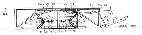
The vehicle of Figures 3 and 4 has two pairs of
wheels 2 on each side and rotationally mounted to
respective wheel support arms 1. Arms 1 are pivotally
mounted to the vehicle by axles 3 which extend across
the vehicle. A suspension component 4, which in this
case is a leaf spring assembly, extends between a mount
on the vehicle provided by pivoting shackle 7 and
equalizing arm 7A and strut 9 (more clearly shown in
Figure 1). The arm 1 is coupled to component 4 via
shackle 8. Shackle 8 is pivotally coupled to both the
component 4 and arm 1.
The strut 9 normally extends along a guide
member 6 when the suspension is lowered and the vehicle
is in the travelling position shown in Figure 3. Each
WO 91/05676 PCT/US90/05856
12
strut terminates in a slide block adapted for screw
threaded engagement with drive screw 11. Screw 11
locates within a support guide member 6A. Extension
shaft 13A forms an extension to screw 11 and terminates
in a sprocket 13.
The draw bar assembly is pivotally connected to
the vehicle and the pivotal movement is controlled by
linkage 17a, 17b and 17c and cam 17d. One end of
linkage 17a is pivotally attached to the lower end of
strut 9. The rotation of cam 17d causes assembly 16 to
rotate and link 17c being adjustable in length ensures
assembly 16 is automatically locked in the horizontal
position. In this way, the assembly 16 can pivot to
maintain a horizontal attitude of the vehicle during
movement of the vehicle between the travelling position
of Figure 3 and the loading position of Figure 4
without requiring decoupling of the vehicle from the
towing vehicle (not shown). Sections 21 and 22 of
screw 11 are of opposite hand and load sharing arm 7A
results in the vehicle having a load sharing tandem
wheel configuration. As a consequence, one arm 1 is a
leading arm and the other is a trailing arm.
To cause the vehicle to move from the Figure 3
travelling position sprocket 13 is driven to rotate
screw 11. This in turn causes one end of component 4
and the end of strut 9 secured to it to move along
guide member 6.. The other end of -strut 9 with guide
block 10 is caused to travel along screw 11. This
~O 91/05676 PCT/US90/05856
13
action pivots arm 1 and raises one end of component 4
and raises wheels 2. Simultaneous with this action
links 17 pivot assembly 16 to ensure that the vehicle
retains a horizontal attitude when the suspension is
raised to cause lowering of the vehicle to the loading
position of Figure 4. Chain 14 links sprockets 13 on
sides of the vehicle and the chain may be driven by
sprocket 15.
To move the vehicle from the Figure 4 loading
position to the Figure 3 travelling position sprocket
13 is rotated in the reverse direction to lower the
suspension and return the vehicle to the attitude of
Figure 3.
Figure 1 shows greater detail of part of the
vehicle suspension and components for raising ailu
lowering the suspension. Support arm 1 is shown
pivotally coupled to axle 3. In this drawing numeral 2
shows where the wheel (omitted for the sake of clarity)
would normally be mounted. Shackle 8 is pivotally
coupled to extend between arm 1 and suspension
component 4. One end of component 4 is connected to
strut 9 and is received within guide member 6. the
other end of component 4 is coupled to shackle 7.
Extension 13a is secured to one end of screw 11
via a coupling 23. The enlarged inset view "SECTION
A-A" shows detail of guide block 10, guide member 6A
and the other or top end of strut 9.
Guide member 6A is of inverted C shaped
WO 91/05676 PCT/US90/05856
14
configuration with two opposed short return flanges
24. The end of strut 9 is forked and has two spaced
fingers 25 secured by fasteners 25A to a main strut
member 26 provided by two L shaped members arranged in
abutting side by side relationship. Slide blocks 5
extend between fingers 25 and member 6A and can either
be short blocks pivotally attached to fingers 25 or
alternatively are long strips extending along and
secured to member 6A. Centre slide block 10 is
pivotally coupled to strut 9 and is threaded to engage
screw 11. Block 10 acts as a traveller and when screw
11 is rotated moves along member 6A to cause that end
of strut 9 to move horizontally and the distal end of
component 4 to move vertically within member 6. The
lower end of member 6 has a bracket 12 secured to it
and slide blocks 5 are secured to the one end of the
spring assembly. When the vehicle is in the travelling
position the strut is wedged between member 6A and
bracket 12.
With reference to Figure 4, it can be seen that
the wheels and suspension on each side of the vehicle
are constructed in a like manner the screws 11 are
linked. That is, extension shafts are coupled.
Sprockets 13 are driven by a chain 14 and the two drive
sprockets 15 can be used to drive one chain 14 and
hence screws 11. Either sprocket 15 may be driven by a
crank (not shown) or a powered system.
~O 91/05676 PCT/US90/05856
Figures 5 and 6 illustrate an alternative
embodiment and like numerals are employed to indicate
like components to that illustrated in other figures.
In these figures (Figures 5 and 6) a vehicle
5 having three pairs of wheels is shown. Unlike the load
sharing tandem arrangement of Figures 3 and 4 these
figures illustrate an independent multi-wheel
arrangement.
The support arms 1 are all trailing arms and
10 each is pivotally coupled to the vehicle by an axle 3
and each has a wheel 2 mounted thereto for rotation. A
suspension component 4 is coupled to extend between the
strut 9 and an inclined frame member 30 of the
vehicle. A shackle 7 secures one end of component 4 to
15 the member 30. Strut 9 is normally aligned with guide
member 6 when in the travelling position of Figure 5.
The vehicle has a similar tow bar assembly tilting
mechanism to that described in relation to Figures 3
and 4.
The suspension shown in Figures 5 and 6 can be
raised to lower the vehicle either by a screw mechanism
like that of Figures 3 and 4 or by an hydraulic
arrangement to be described below. If a screw
mechanism is used, because all arms 1 are trailing
arms, the screw can have a thread of the same hand
completely along an operative part of its length.
An hydraulic cylinder assembly lla having a
WO 91/05676 PCT/US90/05856
16
cylinder 31 and a rod 32 is shown with the rod
retracted in Figure 5. Extension members 33 extend the
length of the rod 32. Slide blocks 10 like that
illustrated in Figure 1 extend between the struts 9 and
the extensions 33 or rod 32 and provide for pivotal
movement between an end of the struts and the member 6A
as the blocks move along member 6A. Extension of the
rod 32 causes struts 9 to move from the Figure 5 to the
Figure 6 position. This movement causes one end of the
component 4 to move along member 6. That end of
component 4 and the adjacent end of strut 9 is
configured like that shown in the inset sectional view
of figure 2 whereas the other end of each of the struts
is configured as shown in the inset sectional view of
Figure 1. Each arm 1 has a shackle 8 extending between
it and component 4.
Figure 2 shows greater detail of the vehicle
suspension. Like components are given like numerals to
that used in Figure 1. An hydraulic cylinder assembly
lla having a cylinder 31 and a rod 32 is shown. Side
blocks 10 like that of Figure 1 are coupled between
each strut 9 and the rod 10 or extension members 33 as
the case may be. The sectional view shows the manner
in which the distal end of component 4 is received by
the guide member 6. Slide blocks 5 slide within the
member 6 and a seal 34 extends between the return
flanges of member 6 and the strut 9. In full outline
w0 91/05676 PCT/US90/05856
17
the rod 32 is shown retracted. When extended, the
components assume the broken line position.