Language selection

Search

Patent 2067810 Summary

Third-party information liability

Some of the information on this Web page has been provided by external sources. The Government of Canada is not responsible for the accuracy, reliability or currency of the information supplied by external sources. Users wishing to rely upon this information should consult directly with the source of the information. Content provided by external sources is not subject to official languages, privacy and accessibility requirements.

Claims and Abstract availability

Any discrepancies in the text and image of the Claims and Abstract are due to differing posting times. Text of the Claims and Abstract are posted:

  • At the time the application is open to public inspection;
  • At the time of issue of the patent (grant).
(12) Patent: (11) CA 2067810
(54) English Title: CASTING APPARATUS FOR CONNECTING A BATTERY PLATE TO A METAL STRAP
(54) French Title: APPAREIL DE COULAGE POUR RACCORDER UNE PLAQUE D'ACCUMULATEUR A UNE COURROIE METALLIQUE
Status: Deemed expired
Bibliographic Data
(51) International Patent Classification (IPC):
  • B22D 39/00 (2006.01)
  • H01M 50/541 (2021.01)
  • B22D 25/04 (2006.01)
  • H01M 2/28 (2006.01)
(72) Inventors :
  • HOPWOOD, ROBERT TIMOTHY (United Kingdom)
(73) Owners :
  • TBS ENGINEERING LIMITED (United Kingdom)
(71) Applicants :
  • TBS ENGINEERING LIMITED (United Kingdom)
(74) Agent: OSLER, HOSKIN & HARCOURT LLP
(74) Associate agent:
(45) Issued: 2001-01-23
(86) PCT Filing Date: 1990-10-16
(87) Open to Public Inspection: 1991-04-21
Examination requested: 1997-08-15
Availability of licence: N/A
(25) Language of filing: English

Patent Cooperation Treaty (PCT): Yes
(86) PCT Filing Number: PCT/GB1990/001593
(87) International Publication Number: WO1991/005625
(85) National Entry: 1992-04-15

(30) Application Priority Data:
Application No. Country/Territory Date
8923690.5 European Patent Office (EPO) 1989-10-20

Abstracts

English Abstract


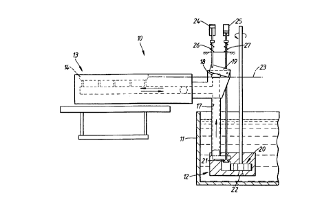
Moulding apparatus (10) includes a lead pot (11), a pump unit (12) and a mould
block (13), having feed duct (14). The feed
duct (14) communicates with the pump unit (12) by means of a supply passage
(17), which is also connected to an overflow outlet
(18), which can be closed by a dump valve (19). In normal operation the level
of the lead in the feed duct is kept to a datum level
(23) defined by the overflow. During 'pouring' however the dump valve (19) is
closed.


French Abstract

Un appareil de moulage (10) comprend un récipient en plomb (11), une unité de pompage (12) et un châssis de moule (13) possédant une canalisation d'amenée (14). La canalisation d'amenée (14) est reliée à l'unité de pompage (12) par l'intermédiaire d'un passage d'alimentation (17) qui est également relié à un orifice d'écoulement (18) pouvant être fermé par une soupape de décharge (19). Pendant le fonctionnement normal, le niveau de plomb dans la canalisation d'amenée est maintenu à un niveau de référence (23) défini par l'orifice d'écoulement. Cependant, ladite soupape (19) est fermée pendant le coulage.

Claims

Note: Claims are shown in the official language in which they were submitted.


THE EMBODIMENTS OF THE INVENTION IN WHICH AN EXCLUSIVE
PROPERTY OR PRIVILEGE IS CLAIMED ARE DEFINED AS FOLLOWS:


1. Apparatus for connecting a battery plate to a metal
strap or post, including a mould having at least one strap or
post cavity and a molten-metal feed duct adjacent thereto, a
weir between the feed duct and the cavity, means for delivering
molten-metal to one end of the feed duct including a pump for
substantially continuous operation and a dump valve for
allowing metal to flow out of the duct to a predetermined datum
level when open and for causing metal to flow over the weir
into the cavity, when closed.
2. Apparatus as claimed in claim 1, wherein there is an
inlet valve between the pump and the feed duct.
3. Apparatus as claimed in claim 1 or claim 2, wherein the
pump is an impeller pump.
4. Apparatus as claimed in any one of claims 1 to 3,
further including means for closing the dump valve only when
the cavity is to be filled.
5. Apparatus as claimed in claim 4, as dependent on claim
2, wherein the means for closing the dump valve operates in
response or in timed relationship with the opening of the inlet
valve.
6. Apparatus as claimed in any one of claims 1 to 5,
including means for driving the pump at more than one speed.
7. Apparatus as claimed in claim 6, further including
means for closing the dump valve when the pump is accelerated.

Description

Note: Descriptions are shown in the official language in which they were submitted.


2~fi'~~~.~ ~~
WO 91/05625 _ 1 _ PCT/GB90/01593
CASTING APPARATUS FOR CONNECTING A BATTERY
PLATE TO A METAL STRAP
This invention relates to casting apparatus of
the type for connecting a battery plate to a metal strap
or post.
Such apparatus was described in our British Patent
No. 2,023,471B. In this arrangement a pump 13 delivers
a metered shot of lead through an inlet valve 203 into a
feed duct 52 causing lead to overflow into mould cavities
51. A dump valve 82 is then opened and the lead in the
feed duct 52 falls back to a datum or constant head level
deffined by the level of the dump valve. Whilst this was
a considerable improvement over existing casting arrange-
ments certain problems have been experienced. First the
inlet valve has a tendency to become clagged so that it
does not seat properly. This results in the feed duct
draining down into the lead pot and as a result the next
"shot" of lead delivered by the,pump results in insufficient
ffilling of the cavities. Further the shockwave resulting
from the delivery of the metered shot of lead causes ripples
in the feed duct and hence incomplete filling of the
cavities.
The present invention consists in apparatus for
connecting a battery plate to a metal strap or post,
including a mould having at least one strap ar post
cavity and a molten-metal feed duct adjacent thereto, a
weir between the feed duct and the cavity, means for
delivering molten-metal to one end of the feed duct


PC1/GB 90/01593
_ ' S ~Se=tSmbeOr9199 9,
including a pump for substantially continuous operation and
a dump valve for allowing metal to flow out of the duct to a
predetermined datum level when open and for causing metal
to flow through the weirs into the cavity, when closed.
By running the pump substantially continuously or
completely continuously the shockwaves can be removed.
In this constant running arrangement the overflowing of the
lead from the feed duct into the cavities can be achieved
in a number of ways. First the pump can be run at a
single speed and overflow is achieved simply by closing
the dump valve. This leads to a rather high circulation
of lead and hence oxide formation. Secondly the pump may
be run at at least two speeds; a first low speed which is
designed simply to prevent the feed duct leaking dawn into
the pot and a second high speed which will deliver an
appropriate amount of lead into the feed duct for the
cavities to be filled. By timing the period of the
second high speed and the operation of the dump valve
the lead could be metered quite precisely. Thirdly the
apparatus may include an inlet valve between the pump
and the feed duct. In this case if the inlet valve
becomes clagged then the pump will prevent any leakage
from the feed duct into the pot, whilst the open dump
valve will prevent the feed duct overflowing. Fourthly,
and indeed preferably the pump may be switched off for a
very short period of time after the lead has flowed into
the eavi~ties, in order to increase the effective head
acting on the lead in the duct and hence the rate at
whicfi. the predetermined datum level is achieved.
In a preferred embodiment the pump is an impeller
pump and means are provided for closing the dump valve
only when the cavities are to be filled. The means for
_...~..~...,~.~..~__. .,.~.,
Unitod ~<,~ f°~ rr~ ' ' ~ ~ "
1 1..1 :r~ ~i J , 11 t tai ~ 'eel ~ (' 1 ~r ex
_-P~..T 1 ~, ~ , _ ,._.. ~ , , 1 ';.:,,


CA 02067810 2000-07-31
- 3 -
closing the dump valve may operate in response or in timed
relationship with the opening and closing of the inlet valve.
Alternatively in the situation where there is no inlet valve
the means for closing the dump valve may operate in relation
to the pump speed or some other cyclic element in the casting
apparatus.
The invention may be performed in various ways and
specific embodiments will now be described, by way of example,
with reference to the accompanying drawings, in which:
Figure 1 is a diagrammatic side view of a casting
apparatus;
Figure 2 is a sectional view through the mould block
of Figure 1; and
Figure 3 illustrates an alternative form of dump
valve.
The apparatus generally indicated at 10 comprises a
lead pot 11, a pump unit 12 and a mould block 13.
The mould block 13 comprises a feed duct 14 separated
from mould cavities 15 by weirs 16. The feed duct communicates
with the pump unit 12 by means of a supply passage 17, which
is also connected to an overflow outlet 18, which can be closed


~ ~ '~ ~.1 ~l
WO 91/05625 PCT/GB90/01593 fi.:~.,
- 4 -
by a dump valve 19.
The pump unit includes an impeller pump 20 and an
inlet valve 21. The impeller pump 20 draws lead in
from the lead pot 11 through an inlet 22 and, when the
inlet valve 21 i~s open, feeds lead up into the supply
passage 17 and hence into the feed duct 14.
In normal operation the level of lead in the
feed duct 14 is kept to a datum level 23 defined by the
overflow 18. VThen lead is to be poured into the mould
cavities 15, the dump valve 19 closes the overflow 18
and the inlet 21 is opened allowing a sustained flow of
lead into the feed duct 19 so that the lead overflows
the weirs 16. The dump valve 19 is then opened and the
inlet valve 21 closed (and the pnrip rlay be moraentarily
switched off) so that the lead in the feed duct falls
back below the height of the weir 16 once sufficient lead
has been poured into the cavities 15.
If, however, the inlet valve 21 becomes clagged so
that it no longer seats properly any downwardly leakage
from the supply passage is prevented by the flow of lead
through the resultant gap up into the passage 17. If
the rate of flow is such that excessive lead is received
in the feed duct 14 then this will be regulated by the
open overflow 18 which maintains the datum level. This
r
method of operation saves a considerable downtime in the
apparatus, because currently pumps are having to be
stripped out once a week.


WO 91/05625 ~ ~, ~ ~ ~ ~ ~ PGT/GB90/01593
- 5 -
As has been mentioned above the alternative
,, operations can be achieved in an arrangement omitting
the inlet valve 21. Both valves are operated by
hydraulic rams.24, 25 against springs 26, 27. The
dump valve is preferably arranged to fail open.
In the drawings the dump valve is shown as a
flap pivoted about an axis extending generally parallel
to the direction of flow through the valve. Alternatively
it may be pivoted about a transverse axis, so it closes
against the flow rather than 'slicing' across it. This
means it is less likely to become jammed by any clag
build up. A further possibility is shown in Figure 3
in this case the dump valve 19 comprises a needle valve
element 30 which locates in an 'open well' outlet 31 at
the head of supply passage 17. The advantage of this
arrangement is that it reduces the surface area of the
lead which is exposed to the air and hence oxidisation
and clagging.

Representative Drawing
A single figure which represents the drawing illustrating the invention.
Administrative Status

For a clearer understanding of the status of the application/patent presented on this page, the site Disclaimer , as well as the definitions for Patent , Administrative Status , Maintenance Fee  and Payment History  should be consulted.

Administrative Status

Title Date
Forecasted Issue Date 2001-01-23
(86) PCT Filing Date 1990-10-16
(87) PCT Publication Date 1991-04-21
(85) National Entry 1992-04-15
Examination Requested 1997-08-15
(45) Issued 2001-01-23
Deemed Expired 2010-10-16
Correction of Expired 2012-12-02

Abandonment History

There is no abandonment history.

Payment History

Fee Type Anniversary Year Due Date Amount Paid Paid Date
Application Fee $0.00 1992-04-15
Maintenance Fee - Application - New Act 2 1992-10-16 $100.00 1992-10-09
Registration of a document - section 124 $0.00 1993-07-27
Maintenance Fee - Application - New Act 3 1993-10-18 $100.00 1993-10-12
Maintenance Fee - Application - New Act 4 1994-10-17 $100.00 1994-10-11
Maintenance Fee - Application - New Act 5 1995-10-16 $150.00 1995-10-13
Maintenance Fee - Application - New Act 6 1996-10-16 $150.00 1996-10-15
Request for Examination $400.00 1997-08-15
Maintenance Fee - Application - New Act 7 1997-10-16 $150.00 1997-10-09
Maintenance Fee - Application - New Act 8 1998-10-16 $150.00 1998-10-07
Maintenance Fee - Application - New Act 9 1999-10-18 $150.00 1999-10-13
Final Fee $300.00 2000-10-11
Maintenance Fee - Application - New Act 10 2000-10-16 $200.00 2000-10-11
Maintenance Fee - Patent - New Act 11 2001-10-16 $200.00 2001-10-09
Maintenance Fee - Patent - New Act 12 2002-10-16 $200.00 2002-10-08
Maintenance Fee - Patent - New Act 13 2003-10-16 $200.00 2003-10-09
Maintenance Fee - Patent - New Act 14 2004-10-18 $250.00 2004-10-04
Maintenance Fee - Patent - New Act 15 2005-10-17 $450.00 2005-10-04
Maintenance Fee - Patent - New Act 16 2006-10-16 $450.00 2006-10-02
Maintenance Fee - Patent - New Act 17 2007-10-16 $450.00 2007-10-01
Maintenance Fee - Patent - New Act 18 2008-10-16 $650.00 2008-10-17
Owners on Record

Note: Records showing the ownership history in alphabetical order.

Current Owners on Record
TBS ENGINEERING LIMITED
Past Owners on Record
DRG (UK) LIMITED
HOPWOOD, ROBERT TIMOTHY
Past Owners that do not appear in the "Owners on Record" listing will appear in other documentation within the application.
Documents

To view selected files, please enter reCAPTCHA code :


To view images, click a link in the Document Description column. To download the documents, select one or more checkboxes in the first column and then click the "Download Selected in PDF format (Zip Archive)" or the "Download Selected as Single PDF" button.

List of published and non-published patent-specific documents on the CPD .

If you have any difficulty accessing content, you can call the Client Service Centre at 1-866-997-1936 or send them an e-mail at CIPO Client Service Centre.


Document
Description 
Date
(yyyy-mm-dd) 
Number of pages   Size of Image (KB) 
Cover Page 1994-04-30 1 15
Description 1994-04-30 5 178
Claims 1994-04-30 1 34
Drawings 1994-04-30 2 34
Abstract 1995-08-17 1 59
Description 2000-07-31 5 177
Claims 2000-07-31 1 38
Drawings 2000-07-31 2 35
Cover Page 2000-12-21 1 43
Description 1997-08-15 5 181
Representative Drawing 2000-12-21 1 8
Representative Drawing 1999-01-05 1 11
Prosecution-Amendment 2000-03-09 2 3
PCT 1992-04-15 11 337
Fees 2003-10-09 1 43
Fees 2000-10-11 1 55
Assignment 1992-04-15 13 398
Prosecution-Amendment 1997-08-15 1 56
Prosecution-Amendment 1998-01-13 3 127
Prosecution-Amendment 2000-07-31 7 194
Correspondence 2000-10-11 1 56
Fees 1998-10-07 1 50
Fees 1999-10-13 1 54
Fees 2001-10-09 1 56
Fees 2002-10-08 1 46
Fees 1997-10-09 1 54
Fees 1996-10-15 1 54
Fees 1995-10-13 1 45
Fees 1994-10-11 1 47
Fees 1993-10-12 1 44
Fees 1992-10-09 1 48