Note: Descriptions are shown in the official language in which they were submitted.
20 68 142
Gas Isolated Disconnecting Switch
and Gas Isolated Switching Device
The present invention relates to a gas isolated switching
device that performs a restriking surge suppressing function
during a switching operation, and in particular, relates to a
gas isolated switching device suitable for use as a gas
isolated disconnecting switch.
In a power generating or transforming station, for
example, the suppression of a surge voltage due to a so-called
restriking surge caused by circuit opening and closing
operations, such as by a disconnecting switch, is an important
problem.
As disclosed for example in JA-A-61-66510 (1986), the
restriking surge due to a switching operation of a gas
isolated disconnecting switch is conventionally suppressed by
mounting a cylindrical magnetic body around the outer
circumference of a conductive body subjected to a high
voltage.
In this conventional art, no special consideration is
given to the influence of an increase in inductance
(impedance) caused by the existence of the cylindrical
magnetic body for suppressing the restriking surge, whereby an
additional recovery voltage is likely to be applied between
the contacts of a circuit breaker when a current is
interrupted by the circuit breaker. As a result, in some
instances the circuit breaker cannot interrupt the fault
current that arises. After such a fault current passes
through the zero point a high recovery voltage appears between
the contacts of the circuit breaker, because of the increased
inductance in the system. As a result, restriking of the
circuit breaker occurs and the current interruption fails.
An object of the present invention is to provide a gas
isolated disconnecting switch or a gas isolated switching
device or switch gear that will not affect the operation of a
circuit breaker in the system, permitting the circuit breaker
to always reliably interrupt a fault current while providing a
sufficient restriking surge suppressing function.
~q~
2 20 68 ~ S2
For achi-eving the above object, a short-circuiting
contact circuit is arranged to bypass a conductor portion that
passes through a magnetic body for suppressing a restriking
surge. The short-circuiting contact circuit is opened only
when a line opening operation by the switch gear is performed.
In the steady state when the switch gear is closed, the
short-circuiting contact circuit functions to bypass a fault
current from the conductor portion that passes through the
magnetic body. Since the impedance of this conductor portion
is larger than that of the short-circuiting contact circuit, a
substantial portion of the fault current flows through the
short-circuiting contact circuit. No increase in inductance
is caused, and any increase of the recovery voltage that might
appear between the contacts of a circuit breaker in the system
is eliminated.
During a line opening operation of the switch gear, since
the short-circuiting contact circuit is opened, a restriking
surge current flows through the conductor portion within the
magnetic body so that a loss of the high frequency current
components at the conductor portion within the magnetic body
is reliably effected and the restriking surge voltage
resulting from the switching operation of the switch gear is
sufficiently suppressed.
In the drawings:
Fig. 1 is a lateral cross section showing one embodiment
of a gas isolated disconnecting switch according to the
present invention;
Fig. 2 (a) to (c) are circuit diagrams for explaining the
operation of this embodiment;
Fig. 3 is a lateral cross section showing another
embodiment of gas isolated disconnecting switch according to
the present invention;
Fig. 4 is a lateral cross section showing a further
embodiment of the invention;
Fig. 5 is a partial side cross section of a further
embodiment taken along the line A-A' in Fig. 4;
-= . ;
~ 0 6 8 1 4 2 ~
Fig. 6 (a) to (c) are circuit diagrams for explaining the
operation of this further embodiment;
Fig. 7 is a lateral cross section showing a still further
embodiment of the invention;
Fig. 8 is a lateral cross section showing an embodiment
of a gas isolated switching device according to the present
invention; and
Fig. 9 is a block diagram for explaining a control system
for this embodiment.
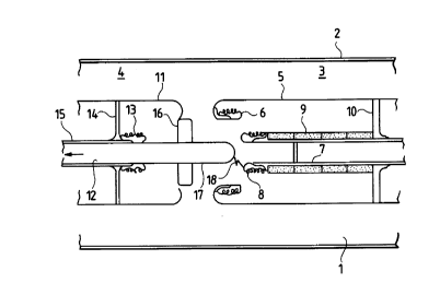
Fig. 1 is an embodiment wherein the present invention is
applied to a gas isolated disconnecting switch, as will be
apparent from the drawing. The switch consists of an electric
line make and break portion constituted by a stationary
assembly 3 and a movable assembly 4 arranged in a grounded
tank 2 filled with SF6 (sulfur hexafluoride) gas 1.
The stationary assembly 3 is composed of a conductor 5
serving as a shield, a main member 6 provided thereon, an
auxiliary conductor 7, an auxiliary member 8 provided thereon
and a cylindrical magnetic body 9 mounted around the auxiliary
conductor 7. The conductor 5 serves as a shield and is
connected to the auxiliary conductor 7 via a mounting bracket
10, the auxiliary conductor 7 extending to a bus-bar (not
shown) of the switch.
The movable assembly 4 is composed of a side shield 11, a
member 12, a contact piece 13, a mounting bracket 14 and a
tube-like conductor 15. At the end of the member 12 there is
a main member 16. Further an auxiliary movable member 17 is
provided at the top end of the movable member 12. In the
disconnecting switch of Fig. 1, the main stationary member 6
constitutes a main stationary contact and the member 16
constitutes a main movable contact. The auxiliary member 8
constitutes an auxiliary stationary contact, while the member
17 constitutes an auxiliary movable contact.
Fig. 1 shows the condition when the switch is opening,
the movable member 12 being on its way towards the fully open
position. A restriking arc 18 is illustrated between contacts
8 and 17.
- ~ B8 1~2
The operation of this embodiment is explained with the
circuits shown in Figs. 2(a), (b) and (c). The circuits each
correspond to an equivalent circuit of the embodiment.
Numeral 20 represent a main contact that is constituted by the
main stationary member 6 and the main movable member 16, and
the numeral 21 represents an auxiliary contact that is
constituted by the auxiliary stationary member 8 and the
auxiliary movable member 17.
The numeral 22 is a main circuit including the main
contact 20, and numeral 23 is an auxiliary circuit including
the auxiliary contact 21. Since the auxiliary circuit 23
includes the cylindrical magnetic body 9, its impedance is
high so that under the steady condition in which both the main
contact 20 and the auxiliary contact 21 are closed a sub-
stantial part of a fault current flows, for example, throughthe main circuit 22. The main circuit 22 thus constitutes a
short-circuiting contact circuit as this phrase is used in the
present invention.
Fig 2 (a) illustrates the condition in which the movable
member 12 is displaced toward the right so that the main
movable member 16 engages the main stationary member 6 and the
auxiliary movable member 17 engages the auxiliary stationary
member, i.e. both the main contact 20 and the auxiliary
contact 21 are closed. As indicated above, this condition is
considered the steady state.
In this steady state, when comparing the main circuit 22
with the auxiliary circuit 23, since the auxiliary conductor 7
constituting the auxiliary circuit 23 and includes the
cylindrical magnetic body 9, the impedance of the auxiliary
circuit 23 is high. Accordingly, a substantial part of a
current, such as a fault current, flowing through the
disconnecting switch in the steady state flows through the
main circuit 22. Thus, when the switch is in this position
there is no increase in impedance of the switch to an unduly
high value with respect to the fault current. Thus there is a
reduced likelihood that an additional recovery voltage will
appear between the contacts of a circuit breaker in the
2~ ~8 ~ 42
'',_.
system, after the fault current has passed the zero point and
that the interruption of the fault current will fail.
Fig. 2 (b) and (c) show an opening operation; first the
main contact 20 is opened, and then the auxiliary contact 21
is opened, i.e. the moving member 12 begins to move in the
arrowed direction in Fig. 1. Accordingly, for the first time
the main movable member 16 is disengaged from the main
stationary member 6, whereby the main contact 20 is opened, as
shown in Fig. 2 (b). In this condition all of the current
passing through the switch is shifted to the auxiliary circuit
23.
When the movable member 12 is moved further in the
arrowed direction, the auxiliary movable member 17 finally
disengages from the auxiliary stationary member 8 and the
auxiliary contact 21 begins to open, which condition is
illustrated in Fig. 2 (c). In the course of this separation
of auxiliary contacts 8 and 17, a restriking arc 18 is
generated at the auxiliary contact 21, as shown in Fig. 2(c).
However, the surge current is reduced by the effect of the
magnetic body 9 and the restriking surge voltage is
suppressed.
Once the condition shown in Fig. 2 (c) has been reached,
both the main contact 20 and the auxiliary contact 21 are
completely opened and the switch is held in the open line
condition.
As a result, the arrangement prevents an interruption
failure of a circuit breaker disposed in the system without
impairing the restriking surge suppressing function of the
disconnecting switch by means of the magnetic body 9.
In the present invention, several kinds of magnetic
materials, such as Permalloy*, iron and ferrite, can be used
for the magnetic body 9. However ferrite is preferable,
because it shows a large loss with respect to high frequency
current components in the range of several 100kHz to several
10MHz.
* Trademark
~ B~ ~ ~2
'
In the present embodiment, a surge voltage is generated
along the longitudinal direction of the cylindrical magnetic
body 9 and may reach about twice the peak value of the
operating voltage of the system. Accordingly, it is necessary
to maintain the dielectric strength of the main stationary
member 6 and the auxiliary stationary member 8 sufficient to
withstand these voltages.
Needless to say, the entire construction of the main
members 6 and 16 and the auxiliary members 8 and 17 has to
balance the configuration and size thereof, while providing
the correct control of the resultant electric field which
varies dependent upon time, so that the restriking arc 18 is
not generated between the main member 6 and the auxiliary
member 17, but is surely generated between the auxiliary
member 8 and the auxiliary member 17.
Fig. 3 shows a modification of the embodiment shown in
Fig. 1, wherein a follow-up type of auxiliary stationary
member 31, including a follow-up spring 30, is provided on the
auxiliary conductor 7 on the stationary member side 3. When
the member 12 begins to move in the arrowed direction during
an opening operation, the follow-up member 31 follows the
auxiliary movable member 17 for a predetermined distance by
virtue of the expansion of the spring 30. Thereafter, the
follow-up auxiliary member 31 disengages from the auxiliary
member 17 due to the force of the spring 30 to restore the
member 31 to its original state.
Accordingly, with the embodiment shown in Fig. 3, by
virtue of the follow-up action of the auxiliary member 31 to
the auxiliary member 17, the opening of the auxiliary contact
21 before the main movable member 16 disengages from the main
stationary member 6 is surely prevented, thereby eliminating
the generation of a restriking arc between the members 16 and
6 and ensuring that the restriking arc 18 is always generated
between the follow-up stationary member 31 and the movable
member 17.
In the embodiment shown in Fig. 4, the cylindrical
magnetic body 9 is disposed near the end of the movable
...,.~
~ ~8 142
assembly 4. At the left end of the movable side shield 11,
which serves as a conductor, there is a main stationary
contact piece 40. A ring shaped movable main contact piece 42
is fitted on the conductor 15 and is adapted to slide on the
5 outer surface thereof upon movement of an operating rod 41 of
the movable member 12. During closure of the switch the main
movable contact piece 42 contacts the main stationary contact
piece 40 whereby a short-circuiting contact circuit is formed
through the member 12, the shield 11, the contact piece 40 and
the contact piece 42. In the steady state a substantial part
of the line current flows through the member 12 and the shield
11 rather than the portion of the conductor 15 that passes
through the cylindrical magnetic body 9 to thereby suppress
the effect of the body 9.
Fig. 5 is a cross section of the conductor 15 taken on
the line A-A' in Fig. 4. On the tube like conductor 15 there
are formed two slits extending in the longitudinal direction
and spaced apart in the radial direction. The main contact
piece 42 is fixed to the operating rod 41 with a supporting
rod 43 through these slits so as to permit the contact piece
42 sliding movement together with the operating rod 41.
The equivalent circuits of the embodiment of Fig. 4 are
shown in Figs. 6(a), (b) and (c). A first main contact 200 is
constituted by the main stationary contact piece 40 and the
main movable contact piece 42, a second main contact 210 iS
constituted by the main stationary member 6 and the movable
member 12, and further the main circuit 22 is constituted by
the shield 11.
In the steady state in which the switch is used to close
an electric power line, the movable member 12 is located at
the right of the drawing by the operating rod 41 and engages
the stationary member 6. At the same time the main movable
contact piece 42 engages the main stationary contact piece 40.
Accordingly, at this time both the first main contact 200
and the second main contact 210 are closed, the equivalent
circuit being seen in Fig. 6 (a). A substantial part of the
line current containing a fault current does not flow through
,~
~ ~ 6 8 1 4 2
the portion of the conductor 15 having increased inductance,
because the conductor 15 passes through the magnetic body 9,
but flows instead through the main circuit 22 so that any
increase of line inductance is eliminated and the possibility
of inducing an adverse effect on the operation of a circuit
breaker in the system and of causing an interruption failure
is avoided.
During an opening operation of the switch, the operating
rod 41 begins to move towards the left in Fig. 4. The
mounting position of the main movable contact piece 42 on the
operating rod 41 is so selected that, in association with
movement of the operating rod 41 towards the left, the main
movable contact piece 42 is at first separated from the main
stationary contact piece 40. With further movement of the
operating rod 41 a predetermined distance towards the left the
movable member 12 is separated from the stationary member 6.
As a result, when a circuit opening operation of the
switch is initiated, it changes from the condition shown in
Fig. 6 (a) to that shown in Fig. 6 (b), wherein due to the
opening of the first main contact 200, all of the current that
has been flowing through the main circuit 22 is shifted to the
conductor 15. Thereafter, as shown in Fig. 6 (c), the second
main contact 210 begins to open and a restriking arc 18 is
generated. However, by this time all of the current has been
shifted to that portion of the conductor 15 that passes
through the magnetic body 9 so that the restriking surge
current associated with the opening operation of the switch
passes through the conductor 15 surrounded by the magnetic
body 9. As a result the circuit opening operation is
completed with suppression of the restriking surge voltage.
Fig. 7 is a still further embodiment in which the
magnetic body 9 is disposed at the final departing portion of
the stationary assembly 3. A main stationary contact piece 50
is provided opposite the conductor 5 which serves as a shield
from the movable member 4. A ring-like main movable contact
piece 51 is slidably disposed on the outer circumference of
the conductor 7 and is connected to a coupling rod 52.
4 ~
At the end of the coupling rod 52 facing the movable
member 12 there is a pushing plate 53, and at its opposite end
there is a supporting rod 54 by which the main movable contact
piece 51 is fixed to the coupling rod 52. The entire coupling
rod 52 is slidably inserted in the conductor 7 and is
maintained in the illustrated position in the steady state by
a return spring 55 held by a stopper 56. The connecting
condition between the contact piece 51 and the supporting rod
54 is the same as that of the embodiment shown in Fig. 5, in
that they are connected to each other through the slits
provided along the conductor 7.
In the steady state in which the switch closes the
circuit, the movable member 12 is located at the right of the
drawing and engages the stationary member 6 and contacts the
pushing plate 53 whereby the coupling rod 52 is moved towards
the right against the force of the spring 55 to engage the
contact piece 51 by the contact piece 50.
This condition corresponds to that shown in Fig. 6 (a)
and operation can be explained with reference to Figs. 6 (a),
(b) and (c) in the same manner as in the embodiment of Fig. 4.
Further, in the embodiment of Fig. 7, the first main circuit
200 is constituted by the main stationary contact piece 50 and
the main movable contact piece 51, while the second main
contact 210 is constituted by the stationary member 6 and the
movable member 12, the main circuit 22 being constituted by
the stationary member conductor 5 serving as a shield and the
mounting bracket 10.
Accordingly, in this steady state a substantial part of
the line current flows through the main circuit 200 having a
low impedance and formed by the movable member 12, the
stationary member 6, the mounting bracket 10, the stationary
conductor 5, the main stationary contact piece 50 and the main
movable contact piece 51, as the short-circuiting contact
circuit. The effect of the cylindrical magnetic body 9 is
suppressed in the steady state so that the possibility of
inducing an adverse effect /on the interrupting operation of a
~0 ~8 ~ 4~
circuit breaker within the system is thus sufficiently
eliminated.
During a circuit opening operation, when the member 12
begins to move towards the left in Fig. 7 from the condition
in which the movable member 12 engages the stationary member
6, the coupling rod 52 also begins to return towards the left
following the movement of the member 12 via the action of the
spring 55. As a result, the main movable contact piece 51
disengages first from the main stationary contact piece 50,
and then the movable member 12 also disengages from the
stationary member 6, i.e. the operating conditions move
sequentially from the steady state as shown in Fig. 6 (a) to
those shown in Fig. 6 (b) and (c). As a result the restriking
surge current during an opening operation is designed to flow
through the conductor surrounded by the magnetic body 9, and
the restriking surge voltage is suppressed.
In the embodiments shown in Fig. 1 and Fig. 3, the
auxiliary stationary member 8 and the auxiliary movable member
17, and the follow-up auxiliary stationary member 31 and the
auxiliary movable member 17 are arranged to be in the
contacting condition in the steady state. However, these can
be constructed so as not to contact mechanically, keeping a
small gap between them. When the construction of these
auxiliary members is thus modified the circuit constituted by
the auxiliary stationary member 8 and the auxiliary movable
member 17 or the follow-up auxiliary stationary member 31 and
the auxiliary movable member 17 is always kept open in the
steady state so that current never flows through it and no
possibility of contact wear arises.
The embodiments shown in Fig. 1 through Fig. 7 show
applications of the present invention to a gas isolated
disconnecting switch. However, as will be apparent from
Fig. 6, it will be understood that the present invention is
applicable to a general gas isolated power transformation
system. The objects of the present invention can still be
achieved in a case in which a cylindrical magnetic body is
provided on a gas isolated bus-bar conductor at any desired
E~
4 2
11
position to suppress the restriking surge caused by a gas
isolated disconnecting switch, by means of a contact connected
in parallel with the conductor. Accordingly, an embodiment of
a gas isolated switching device constituted by applying the
present invention to a general gas isolated power trans-
formation system is shown in Fig. 8.
In Fig. 8, a gas isolated bus-bar conductor 60 located at
any desired position in the system is provided with a
cylindrical magnetic body 61 that is covered by a shield 62
serving as a conductor for maintaining isolation from the
grounded tank 2. The shield 62 and the conductor 60 are
respectively provided with contact pieces 63 and 64, the
conductor 60 being further provided with an annular movable
member 65 for slidable movement thereon.
When the movable member 65 is moved to the right in the
drawing, it contacts both contact pieces 63 and 64, whereby a
short-circuiting contact circuit 66 is formed that bypasses
the portion of the conductor 60 that passes through the
magnetic body 61. In the present embodiment, a shield 67 is
provided near the movable member 65 on the side opposite the
shield 62 to achieve isolation from the grounded tank 2.
The movable member 65 is moved by an insulated operating
rod 68 to make or break the contact circuit 66.
The contact circuit 66 is so controlled that, in the
steady state in which a gas isolated disconnecting switch
connected in series with the conductor 60 is closed, a
substantial part of a fault current does not pass through the
portion of the conductor 60 surrounded by the magnetic body
61, except for the region in which such fault current
approaches zero. During the transient state of a circuit
opening operation generated by the disconnecting switch, the
restriking surge current is caused to pass through the portion
of the conductor surrounded by the magnetic body 61. For this
purpose, between operating circuits 72 and 73 for a gas
isolated disconnecting switch 70 and the contact circuit 66,
respectively, a delay circuit 74 is provided, as shown in
4 2
-
12
Fig. 9, to perform a control sequence to open the contact
circuit 66 immediately before the opening of the gas isolated
disconnecting switch 70.
Therefore, according to the present embodiment, with the
provision of a magnetic body 61 on a conductor located at any
desired position in a gas isolated switching device, a
possible restriking surge voltage is effectively suppressed.
The restriking surge voltage suppressing effect achieved
by the above embodiments is explained. When the loss caused
by the cylindrical magnetic body with respect to the surge
current, which is converted to an equivalent resistance, is
selected to be equal to or more than the surge impedance of
the gas isolated bus-bar, the restriking surge voltage is
suppressed below 2pu (wherein lpu is a peak value of the
operating voltage of the system with respect to ground).
11',, ~
~ . .