Note: Descriptions are shown in the official language in which they were submitted.
2068 160
RD-20,853
- 1 -
SHIELDEI) TAR':CING COIL FOR AN ELECTRODELESS
HI .H INTENSITY DISCHARGE LAMP
Related Patent A~blication
This application is related to commonly assigned,
Canadian patent application serial no. 2,068,151, now
abandoned, of S. A. E1.-Hamamsy, J. P. Cocoma and G. A.
Farrall.
Field of the Invention
The pre~~ent invention relates to starting circuits
for electrodeless high intensity discharge (HID) lamps and,
more particularly, to such a starting circuit including a
to starting coil that is shielded from stray capacitances.
Backa»nd of the Invention
In a high intensity discharge (HID) lamp, a medium
to high pressure ioni2;able gas, such as mercury or sodium
vapor, emits visible radiation upon excitation typically
caused by passage of current through the gas. One class of
HID lamps comprises electrodeless lamps which generate an
arc discharge by generating a solenoidal electric field in
a high-pressure gaseoL~s lamp fill. In particular, the lamp
fill, or discharge plasma, is excited by radio frequency
(RF) current in an excitation coil surrounding an arc tube.
The arc tube and excitation coil assembly acts essentially
as a transformer whicl-., couples RF energy to the plasma.
That is, the excitation coil acts as a primary coil, and
the plasma functions a.s a single-turn secondary. RF current
in the excitation coil produces a time-varying magnetic field,
in turn creating an electric field in the plasma which closes
completely upon itself, i.e., a solenoidal electric field.
20 68 1 60
- 2 -
RD-20,853
Current flows as a re:>ult of this electric field, resulting
in a toroidal arc discharge in the arc tube.
At room temperature, the solenoidal electric field
produced by the excitation coil is typically not high
enough to ionize the gaseous fill and thus initiate the arc
discharge. One way to overcome this shortcoming is to
lower the gas pressure of the fill, for example, by first
immersing the arc tube' in liquid nitrogen so that the gas
temperature is d.ecrea~oed to a very low value and then
1o allowing the gas temperature to increase. As the
temperature rises, an optimum gas density is eventually
reached for ionization, or breakdown, of the fill to occur
so that an arc discharge is initiated. However, the liquid
nitrogen method of initiating an arc discharge is not
practical for widespread commercial use.
More recent methods for starting electrodeless HID
lamps entail using starting aids to capacitively couple the
high voltage developed across the excitation coil turns
into the arc tube. A~, a result of this voltage gradient, a
2o capacitive current flows between the starting aid and the
excitation coil, and hence through the arc tube, thereby
ionizing the gaseous fill and producing a low current glow
discharge therein. WY:.en the gas is sufficiently ionized, a
transition is made from a relatively low current glow
discharge to a relatively high current, high intensity
solenoidal arc discharge. Such a starting aid may
comprise, for example, a pair of capacitive starting
electrodes, as described in U.S. Patent No. 4,902,937 of H.
L. Witting, issued February 20, 1990, and assigned to the
3o instant assignee. Each starting electrode comprises a
conductive ring which surrounds the arc tube and is
connected to the' excitation coil of the HID lamp.
Coupling a high voltage signal between the pair of
starting electrodes causes an electric field to
'~~ 68 ~ 6 0
- 3 -
RD-20,853
be produced therebetween which is of sufficient magnitude
to create a glov,~ discharge in the arc tube due to the arc
tube wall capacitance. Furthermore, as it has been
determined that the application of relatively large
electric fields directly to the arc tube via the starting
aid may cause early arc tube degradation, heat sensitive
members, e.g. bimetall.ic strips, are utilized for moving
the starting electrodes away from the arc tube after
initiating an arc discharge, thereby preserving the useful
life of the lamp.
Recently developed fixed starting aids for
electrodeless HID lamps include means for removing the
starting voltage from a fixed starting electrode after
initiation of the arc discharge. For example, a gas probe
starter includes a fixed starting electrode coupled to a
starting chamber containing a gas, preferably at a low
pressure relative to that of the arc tube fill, which
chamber is attached to the outer surface of the arc tube.
One such starting aid is the subject of commonly assigned
Roberts et al. U.S. pa.tent 5,095,249, issued March 10,
1992. As described in the Roberts et al. patent, a
starting voltage is applied to the starting electrode by a
starting circuit, causing the low-pressure gas in the
starting chamber to become conductive. As a result, a
sufficiently high voltage is applied to the arc tube to
ionize the gaseous fill in the arc tube, thus forming an
arc discharge therein. After the lamp has started, the
starting voltage is removed from the starting electrode in
order to extinguish th.e discharge current in the chamber
3o which would otherwise have a detrimental effect on the arc
tube wall.
A suitable starting circuit for applying a starting
voltage to either a fixed or movable starting aid is
described in commonly assigned, U.S. patent 5,059,868 of S.
35~ A. E1-Hamamsy and R. J~. Thomas, issued October 22, 1991.
v
2068960
- 4 -
RD-20,853
The starting circuit of the E1-Hamamsy and Thomas patent
comprises a high-efficiency power supply, including a tuned
output circuit, for providing an RF signal to the starting
electrode. Exe~r~plary high-efficiency power supplies useful
in the E1-Hamamsy and Thomas starting circuit comprise
Class-D and Class-E power amplifiers. The starting circuit
operates at a higher frequency than that used to operate
the lamp ballast which drives the excitation coil. In this
way, the starting circuit is independent of the lamp
to ballast circuit and, therefore, does not interfere with the
operation thereof.
Another suitable starting circuit is described in
J. P. Cocoma and. G. A. Farrall Canadian patent application
no. 2,056,552, filed rfovember 28, 1991, which is assigned
to the instant assignee. Cocoma and Farrall describe a
passive starting circuit wherein a series resonant circuit
is tuned to provide a starting voltage substantially
simultaneously with the application of power to the
excitation coil from the main power source.
2o One shortcoming of passive starting circuits is
that stray capacitance effects can cause detuning,
resulting in less than, optimum performance. Furthermore,
the reliance on stray capacitances to tune the circuit
implies that even slight layout changes (e. g., the position
of the coil in the circuit) cause significant detuning of
the starting circuit. Therefore, it is desirable to avoid
such stray capacitance effects and thus optimize starting
circuit performance, i.e. enhance starting reliability.
Obiects of the Invention
2~~~i ~~
- 5 -
RD-20,853
Accordingly, an object of the present invention is
to provide a new and improved starting circuit for an
electrodeless HID lamp.
Another object of the present invention is to
provide a starting circuit for an electrodeless HID lamp
which includes shielding from stray capacitances in order to
avoid detuning the starting circuit.
Another object of the present invention is to
provide a starting coil for an electrodeless HID lamp having
a capacitive shield.
Another obect of the present invention is to
provide a passive starting circuit including tuning
capacitances which are controlled by suitable construction of
the starting circuit.
~~nmaryr of h Inv -rr, nn
The foregoing and other objects of the present
invention are achieved in a passive, resonant starting
circuit for an electrodeless HID lamp including a starting
coil and shielding means for shielding the starting coil from
stray capacitances which would otherwise result in detuning
the resonant circuit and hence decrease starting reliability.
The starting circuit further includes a capacitance coupled
in series with the starting coil and another capacitance
coupled in parallel with the coil. In a preferred
embodiment, the starting coil is enclosed in a conductive
housing which functions as both a shield and the resonant
capacitance in parallel with the starting coil. Preferably,
the housing is cylindrical and has a lengthwise gap so as to
prevent the housing from functioning as a short circuit
secondary winding with respect to the starting coil. A
conductive disk is also preferably mounted to the lower
voltage, or ground, end of the housing to increase shielding
even further.
~~~I,~'~'~'~~'1
UJ
- 6 -
RD-20,853
$,;rief D~S~,ot,' on of h D awi nc~~
The f~~ature,s and advantages of the present
invention will become apparent from the following detailed
description of t:he invention when read with the accompanying
drawings in which:
Figures 1 is a schematic illustration of an
electrodeless HI:D lamp system employing a starting circuit,
including a shielded :>tarting coil, according to the present
invention; and
Figures 2 is a front view of a shielded starting
coil in a starting circuit according to a preferred
embodiment of the present invention.
Detailed Deacrinti on of h Tnv n i nn
Figures 1 il:Lustrates an electrodeless HID lamp
system including' an HI:D lamp 10, a starting probe 20, a radio
frequency (RF) r~allast: 30, and a starting circuit 40. HID
lamp 10 includes an arc tube 14 preferably formed of a high
temperature glass, such as fused quartz, or an optically
transparent or translucent ceramic, such as polycrystalline
alumina. An excitation coil 16 surrounds arc tube 14 and is
coupled to RF ba.llast 30 for exciting a toroidal arc
discharge 18 therein. (For clarity of illustration, coil 16
is not shown in its operational position about arc tube 14.)
By Way of example, arc: tube 14 is shown as having a
substantially ellipsoid shape. However, arc tubes of other
shapes may be desirable, depending upon the application. For
example, arc tube 14 may be spherical or may have the shape
of a short cylinder, or "pillbox", having rounded edges, if
desired.
Arc tube 14 contains a fill in which an arc
discharge 18 having a substantially toroidal shape is excited
during lamp operation. A suitable fill is described in U.S.
~0681fi0
RD-20,853
Patent No. 4,81C),938 of P. D. Johnson, J. T. Dakin and J.
M. Anderson, is:~ued on March 7, 1989, and assigned to the
instant assignee'. The' fill of the Johnson et al. patent
comprises a sodium halide, a cerium halide and xenon
combined in weight proportions to generate visible
radiation exhibiting high efficacy and good color rendering
capability at white color temperatures. For example, such
a fill according to the Johnson et al. patent may comprise
sodium iodide and cerium chloride, in equal weight
1o proportions, in combination with xenon at a partial
pressure of about 500 torr. Another suitable fill is
described in commonly assigned U.S. Pat. No. 4,972,120 of
H. L. Witting, issued Nov. 20, 1990. The fill of the
Witting patent c:ompri:~es a combination of a lanthanum
halide, a sodium halide, a cerium halide and xenon or
krypton as a buffer gas. For example, a fill according to
the Witting patent may comprise a combination of lanthanum
iodide, sodium iodide, cerium iodide, and 250 torr partial
pressure of: xenon.
2o RF power is applied to the HID lamp by RF ballast
30 via excitation coi:L 16 coupled thereto. A suitable
excitation coil 16 may comprise a two-turn coil having a
configuration such as that described in commonly assigned,
U.S. patent 5,0;39,903 of G. A. Farrall, issued August 13,
1991. Such a coil configuration results in very high
efficiency and causes only minimal light blockage from the
lamp. The over-all shape of the excitation coil of the
Farrall patent is ger.,erally that of a surface formed by
rotating a bilaterally symmetrical trapezoid about a coil
3o center line situated in the same plane as the trapezoid,
but which line does not intersect the trapezoid.
However, other suitaf~le coil configurations may
.. : H
c 20 6 ~ 1 6 0
-8_
RD-20,853
be used with the starting aid of the present invention,
such as that described in commonly assigned U.S. Pat. No.
4,812,702 of J. M. Anderson, issued March 14, 1989. In
particular, the Ander:~on patent describes a coil having six
turns which are arranc3ed to have a substantially V-shaped
cross section on each side of a coil center line. Still
another suitable excitation coil may be of solenoidal
shape, for example.
In operation, RF current in coil 16 results in a
1o time-varying magnetic field which produces within arc tube
14 an electric field that completely closes upon itself.
Current flows through the fill within arc tube 14 as a
result of this :>olenoidal electric field, producing
toroidal arc di:>charge 18 therein. Suitable operating
i5 frequencies for RF ballast 30 are in the range from 0.1 to
300 megahertz (MHz), exemplary operating frequencies being
6.78 MHz and 13.56 MHz.
By way of example, ballast 30 is illustrated as
comprising a Cl~~ss-D power amplifier, such as the ballast
20 described in commonly assigned, U.S. patent 5,047,692 of S.
A. E1-Hamamsy and J. C. Borowiec, issued September 10,
1991. The Clas:a-D ballast includes two switching devices
Q1 and Qz connected in series with a do power supply VDD in
a half-bridge configuration. Switching devices Q1 and Q2
25 are illustrated as MOSFET's, but other types of switching
devices having c:apacii~ive gates may be used, such as
insulated gate bipolar transistors (IGBT's) or MOS-
controlled thyr=_stors (MCT's). Switching devices Q1 and Q2
are coupled to ballast= driver 32 via input isolation
30 transformers 34 and 36, respectively. In operation, the
switching devices are' driven alternately between cutoff
and saturation such that one is conducting while the
other one is turned off and vice versa. Hence, the
Class-D ballast may be conveniently driven by a square
35 wave signal. Alternatively, ballast driver 32
.20 6a ~ 60
- 9 -
RD-20,853
may comprise means for generating two out-of-phase
sinusoidal signals, as described in Canadian patent
application of ~~. A. El-Hamamsy and G. Jernakoff, serial
no. 2,037,375 filed February 28, 1991.
A resonant lo<~d network is connected to the half-
bridge at the junction between switching devices Q1 and Q2
and in parallel with switching device Q2. The resonant
load network comprises the excitation coil 16 of HID lamp
and a tuning capac_~tor Cp connected in parallel
to therewith. The paral=Lel combination of capacitor Cp and
coil 16 functions as an impedance transformer to reflect
the impedance of: the arc discharge 20 into the ballast
load. A bl.ocking/tuning capacitor CS is connected in
series with the parallel combination of coil 16 and
capacitor CP. In particular, capacitor CS is used both for
blocking do voltage and for resonant circuit tuning. As
described i.n the' E1-Hamamsy and Borowiec patent
application, cited hereinabove, capacitors Cs and CP are
chosen to ensure' impedance matching for maximum efficiency.
2o By way of example, starting probe 20 is illustrated
in Figure 1. as comprising a gas probe starter, such as that
described in commonly assigned, Roberts et al. U.S. patent
5,095,249, cited here:inabove. As described by Roberts et
al., gas probe :tarter 20 comprises a starting electrode 22
coupled to a st~~rting chamber 24 which is attached to the
outer wall of arc tuba 14 and contains a gas. The gas in
starting chamber 24 may comprise, for example, a rare gas
at a pressure in the range from approximately 0.5 to 500
torr, with a preferred range being from approximately 5 to
40 torr. Preferably, the gas in chamber 24 is at a low
pressure relative to that of the arc tube fill in order
to promote even easier starting. In an exemplary HID
lamp system, a suitable arc tube fill pressure
... ,
2068~~0
- 10 -
RD-20,853
may be approximately 200 torr while that of the gas in
starting chamber 24 may be approximately 20 torr. It is to
be understood, however-, that the starting circuit of the
present invention may be used with other suitable types of
starting probes, such as a fixed foil electrode of the type
described in commonly assigned, E1-Hamamsy and Thomas U.S.
patent 5,095,86E~, cited hereinabove. Still other suitable
starting electrodes may be movable, if desired, such as
those described in: Witting U.S. Pat. No. 4,902,937;
Witting U.S. Pat:. No. 4,894,590; and Borowiec U.S. Pat. No.
4,894,589.
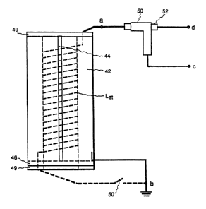
As shown in Figure 1, starting circuit 40 comprises
a passive resonant LC circuit including starting coil Lst,
having a high vc>ltage terminal a and a low voltage terminal
.h, a capacitance Cgtp coupled in parallel with starting coil
Lst, and a capacitance Cses coupled in series with starting
coil Lst. In accordance with the present invention, the
starting coil Lst includes shielding means for shielding the
coil from external capacitances which could otherwise cause
2o starting circuit. 40 to become detuned, thereby reducing
circuit efficiency. 7:n a preferred embodiment, as shown in
Figure 2, the st:artin<~ coil is enclosed in a preferably
cylindrical hou:;ing 4:? comprised of a suitable conductor,
e.g. copper or aluminum. The cylindrical housing has a
lengthwise gap 9:4 formed therein in order to prevent the
housing from acting a:~ a short circuit secondary winding
with respect to starting coil Lst.
Advantageously, the capacitance between the
housing, or shield, 4:? and the coil Lst comprises the
parallel starting capacitance Cstp of starting circuit 40.
In particular, t:ze capacitance Cstp is determined by the length
of the cylindric,~l hou:~ing 42 and the distance between coil
Lst and shield 42. The distance between the coil and the
w~~~.~~~
- 11 -
RD-20,853
shield must be sufficiently large so that the air within the
housing (i.e., between the high voltage terminal a of
starting coil L,~t and housing 42) does not break down when the
high RF voltage needed to initiate the discharge in the arc
tube is applied by they lamp ballast.
As shown in Figure 2, a preferred embodiment of the
shielding means further includes a conductive disk 46,
preferably made of the' same conductive material as housing
42, soldered on the ground side of cylindrical housing 42 for
increasing the :shielding capability of the starting coil. A
conductive disk is not. mounted on the higher voltage side of
the starting coil (at terminal a) in order to further ensure
against the break down of air within the housing between the
high voltage terminal a of the starting coil and the shield.
A high-voltage i.nsulat:ing disk 49 is preferably mounted on
either end of housing 42. Such a high-voltage insulating
disk may be comprised of, for example, synthetic resin
polymers such a~: those' sold under the trademark Teflon.
In a p referred construction of starting circuit 40,
series capacitor Csts comprises a coaxial capacitor. As shown
in Figure 2, the coaxial series capacitor Csts is formed
between the high. voltage terminal a of starting coil Lst and
an external, cylindrical, conductive band 50 mounted on an
insulating sleeve 52. The inside diameter of the insulating
sleeve is preferably ~;maller (e. g., on the order of 1-2 mils
smaller) than th.e out~;ide diameter of the high voltage lead
from the starting coil. Lst. During assembly, the high voltage
lead from the startincr coil Lgt is coated with a dielectric
grease, such as, for example, that sold under the trademark
General Electric Silicone Dielectric Grease. The high
voltage lead is then forced through insulating sleeve 52. In
this way, air is prevented from being trapped between the
high voltage lead and the insulating sleeve, thus avoiding
dielectric breakdown therebetween. Finally, an insulating
_._
- 12 -
RD-20,853
layer is disposed over- conductive band 50. The capacitance
of coaxial series capacitor Cst~ is thus controlled by the
width of cnducti.ve bard 50, the dielectric constant of
insulating sleeve 52, and the thickness of insulating sleeve
52. As shown, conductive band 50 is connected to the high
voltage side of the e~s:citation coil at point c in the circuit
of Figure 1; ands, the high voltage lead from coil Lst, through
insulating sleeve 52, is connected to the gas probe starter
at point d in th.e circuit of Figure 1.
In operation, upon application of an RF signal to
excitation coil 16, starting circuit 40 resonates to a
sufficiently high voltage to cause the gas in chamber 24 to
break down, or ionize, and thus become conductive. As a
result, a relatively l.ow discharge current flows between
electrode 22 and. the a.rc tube wall. The discharge in the
starting chamber may b~e characterized as either a glow
discharge or an arc discharge, depending upon the pressure of
the gas in chamber 24. At the low-end of the aforementioned
gas pressure range, th.e discharge is more likely to be
characterized as a glow, while at the high-end of the gas
pressure range, the discharge is more likely to be
characterized as an arc. However, there is no generally
accepted definition which distinguishes between glow and arc
discharges. For example, as described by John H. Ingold in
"Glow Discharges at DC and Low Frequencies" from Gaseous
Electronics, vol. I, edited by M.N. Hirsh and H.J. Oskam,
Academic Press, New York, 1978, pp. 19-20, one definition is
based on electrode-related phenomena, and another is based on
electron and particle temperatures. In any event, as a
result of the discharge current in starting chamber 24, a
sufficiently high starting voltage is capacitively coupled to
the inside surface of arc tube 14 which causes the high-
pressure gaseous fill contained therein to break down,
thereby initiating arc discharge 18.
20 6 g 1
- 13 -
RD-20,853
In an al.ternat:ive embodiment of starting circuit
40, as shown in phantom in Figure 2A, a glow suppression
relay 50 is employed i.n series with the starting coil Lsc-
Such a glow suppression relay is described in Cocoma and
Farrall Canadian. Patent application no. 2,056,552, noted
above. The glow suppression relay is employed to detune
the resonant starting circuit after initiation of the
discharge so that the starting voltage is decreased
sufficiently to extinguish the glow discharge in the
to starting chamber. During lamp start-up, relay 50 is
closed. However, after initiation of the arc discharge in
the arc tube, relay 50 is opened, thus effectively removing
starting coil LS_ from starting circuit 40. The starting
circuit is thus detuned, and the glow discharge is
extinguished. A.s a result, the flow of leakage currents
between the starting chamber 24 (Figure 1) and the arc
tube, which would otherwise eventually have a detrimental
effect on the arc tube wall, is avoided.
While the preferred embodiments of the present
2o invention have been shown and described herein, it will be
obvious that such embodiments are provided by way of
example only. Numerous variations, changes and
substitutions will occur to those of skill in the art
without departing from the invention herein. Accordingly,
it is intended that the invention be limited only by the
spirit and scope of the appended claims.