Note: Descriptions are shown in the official language in which they were submitted.
2068252
WAVELENGTH-ASSIGNABLE OPTICAL COMMUNICATION SYSTEM
Background of the Invention:
1. Field of the Invention:
The present invention relates to an optical
communication system, and, more particularly, to an
optical communication system capable of assigning an
unused wavelength to a connection request from a network
in accordance with the wavelengths being used in a
wavelength-multiplex communication path. Such a system
includes a wavelength-sharing optical exchange system
which assigns, to a call, a wavelength suitable for a
condition of the exchange network at the time of call
and wavelength-multiplexes a plurality of calls so as
to effectively utilize a wavelength band.
2. Description of the Prior Art:
In an optical communication system according to the
prior art which accommodates a plurality of terminals by
using wavelength-multiplex communication paths, different
wavelengths inherent to the respective terminals are assigned
thereto for transmission or reception, so that signals having
the same wavelength may not be transmitted through the same
wavelength-multiplex communication path. For example, Fig. 1
is a diagram illustrating a conventional optical star-type
communication network. In Fig. 1, the reference numeral 201
designates a terminal; 202 a signal source; 203 a transmis-
sion light source; 204 a photocoupler; and 205 a receiving
circuit capable of selecting a wavelength. Fig. 2 is a
diagram illustrating a conventional optical concentrating
2068252
system using wavelength-multiplex communication paths. In
Fig. 2, the reference numerals 201-1 through 201-n designate
terminals; 206 a wavelength-multiplex communication path;
207 a network accommodating wavelength-multiplex communica-
tion paths 206; and 208 an interface for interconnecting
communication paths 206 and network 207.
In operation, a wavelength ~1 inherent to terminal
201-1 is assigned to transmission light source 203 contained
in terminal 201-1. When a signal is transmitted to terminal
201-1 from any other terminal, a signal having wavelength
~1 is transmitted to terminal 201-1 via photocoupler 204
and then receiving circuit 205 in terminal 201-1 selects
the signal having wavelength ~1 and receives it. Upon
transmission, each terminal decides whether an optical
signal having the same wavelength as that of the signal to
be transmitted exists on the communication path. If there
is no such optical signal on the communication path, that
terminal starts transmission of the signal. In Fig. 2,
wavelengths ~1 through ~n for transmission are fixedly
assigned to transmission light sources 203 in the respective
terminals 201-1 through 201-n, such that the wavelengths
are not overlapped. Optical signals transmitted from the
respective terminals are multiplexed on wavelength-multiplex
communication path 206 via photocouplers 204 and coupled to
network 207.
As explained above, in a method of fixedlY assigning
to terminals reception wavelengths and transmission
wavelengths inherent to the respective terminals, the
2~68252
number of terminals is limited by the wavelengths because
each wavelength corresponds to one particular terminal.
Even if the wavelength assigned to one terminal is not
in use, this wavelength cannot be used by other terminals,
resulting in inefficient utilization of wavelength.
Fig. 3 illustrates a space-sharing optical exchange
system as disclosed in the Japanese Patent Public Disclosure
No. 48895/87. In Fig. 3, the reference numerals 301 through
304 designate terminals; 305 an optical switchboard; 341
through 344 subscriber optical fibers; and 351 through 354
optical switches. Respective terminals 301 through 304 each
include two light sources having wavelengths ~1 and ~2 and
select either one of the wavelengths for transmission.
In operation, switchboard 305 directly interconnects
optical switches 351 and 354. Each of terminals 301 through
304 includes two light sources having wavelengths of ~1
and ~2 as explained above and selects an optical signal
having either one of the wavelengths for transmission.
For example, if communication is required between terminal
301 and terminal 304, terminal 301 transmits a signal
having wavelength ~1 while terminal 304 transmits a signal
having wavelength ~2. At the same time, switchboard 305
establishes a communication path running from subscriber
fiber 341 through optical switches 351 and 354 to subscriber
fiber 344. In this way, terminals 301 and 304 may be
interconnected. Before communication between two terminals
is commenced, transmitting and receiving wavelengths to
be used by each terminal are instructed by a subscriber
-- 3
2068252
signal from a control circuit of optical switchboard 305
to a control circuit of the respective terminals.
As explained above, according to a system of
assigning a wavelength to a call, respective terminals and
an optical switchboard are interconnected in a star form,
requiring a high cost of concentration. Besides, since
wavelength-multiplexing is merely available for upward and
downward signals in a wavelength-multiplex communication
path, a transmission band contained in a wavelength range
is not effectively utilized. Since a network capacity is
limited by a spatial switch, any increase in capacity is
difficult due to the structure of devices used. If terminals
are further added later on, the switchboard has to be
modified.
Summary of the Invention:
The present invention has been proposed to eliminate
such problems as pointed out above, and an object of the
present invention is to provide an optical communication
system which is capable of effectively utilizing wavelengths
by assigning a wavelength to a call from a terminal in
accordance with a connection request from the terminal,
avoiding interference occurred by using the same wavelength
on a wavelength-multiplex communication path and easily
increasing the number of terminals.
Another object of the present invention is to
provide a wavelength-sharing optical exchange system which
is capable of effectively utilizing a transmission band
contained in a wavelength range of a wavelength-multiPleX
. 2068252
.
communication path, accommodating terminals in respective
wavelength-multiplex communication paths, the number of
the terminals being more than the number of multiplexed
wavelengths, having a large network capacity, eliminating
S the necessity of wavelength modulation within an optical
switchboard and easily controlling the switchboard.
Further object of the present invention is to
provide an optical switch unit suitable for the
wavelength-sharing optical exchange system and capable of
spatially and independently exchanging optical signals of
different wavelengths in respective wavelength-multiplex
communication paths accommodated in the optical exchange
system.
In order to attain the above-described objects,
an optical communication system according to the present
invention comprises a wavelength control unit which is
capable of monitoring wavelengths used in wavelength-
multiplex communication paths, selecting a wavelength
unused in any wavelength-multiplex communication path in
response to a connection request made by means of a
control wavelength from a terminal and informing the
calling and a called terminals of the selected wavelength
using the control wavelength.
In one aspect, the present resides in an
optical communication system comprising:
a plurality of wavelength-multiplex
communication paths for transmitting a plurality of
2068252
-
optical wavelength signals;
a network connected to said plurality of
wavelength-multiplex communication paths;
a plurality of terminals connected to said
plurality of wavelength-multiplex communication paths,
each terminal capable of generating and outputting a
connection request signal at a predetermined control
wavelength and setting a transmission wavelength and a
reception wavelength, each to a selected unused
wavelength, in response to a wavelength information
signal;
a wavelength controller separate from the
plurality of terminals and coupled to one of the
plurality of wavelength-multiplex communication paths,
which in response to the connection request signal output
by a calling terminal selects the unused optical
wavelengths on said wavelength-multiplex communication
paths and outputs the wavelength information signal
containing information relating to the selected
wavelengths at the control wavelength.
In a further aspect, the present invention
resides in a wavelength-sharing optical exchange system
comprising:
a plurality of wavelength multiplex
communication means for transmitting a plurality of
optical wavelength signals;
terminal means, coupled to said communication
- 5a -
~,
~Ob825~
means, for generating and outputting a connection request
signal at a predetermined control wavelength and for
setting a transmission and a reception wavelength, each
to an unused wavelength, in response to a wavelength
information signal;
line control means, separate from said
plurality of terminal means and coupled to one of said
plurality of communication means, for detecting the
connection request signal and for generating and
outputting the wavelength information signal, at the
control wavelength, containing information relating to
the selected unused wavelengths;
channel control means, coupled to said line-
control means, for selecting the unused wavelengths for
an optical communication signal to be transmitted over
said communication means and for outputting a control
signal; and
an optical switch means for establishing a
communication path between the plurality of communication
means in accordance with the control signal output from
said channel control means.
In yet a further aspect, the present invention
resides in an optical communication system comprising:
a plurality of wavelength-multiplexed
communication means for transmitting a plurality of
optical wavelength signals;
a plurality of terminal means, coupled to the
- 5b -
~.
2C6~2~
plurality of wavelength-multiplex communication means,
for generating and outputting a connection request signal
at a predetermined control wavelength and for setting a
transmission and a reception wavelength, each to an
unused wavelength, in response to a wavelength
information signal;
wavelength control means, separate from the
plurality of terminal means and coupled to one of the
plurality of communication means, for receiving the
connection request signal output by a calling terminal,
for selecting the unused optical wavelengths on the
wavelength-multiplex communication means and for
outputting the wavelength information signal containing
information relating to the selected wavelengths at the
control wavelength.
In yet a further aspect, the present invention
resides in a wavelength-sharing optical exchange system
comprising:
a plurality of wavelength-multiplex
communication paths capable of transmitting a plurality
of optical wavelength signals;
a plurality of terminals, coupled to the
plurality of wavelength-multiplex communication paths,
which generate and output a connection request signal at
a predetermined control wavelength and set a transmission
and a reception wavelength, each to an unused wavelength,
in response to a wavelength information signal;
- 5c -
~.
2068252
a subscriber-line controller, separate from the
plurality of terminals and coupled to one of the
plurality of wavelength-multiplex communication paths,
which detects the connection request signal and generates
and outputs the wavelength information signal, at the
control wavelength, containing information relating to
the selected unused wavelength;
a channel controller, coupled to the
subscriber-line controller, which selects the unused
wavelength for an optical communication signal to be
transmitted over the wavelength-multiplex communication
paths and which generates and outputs a control signal;
and
an optical switch network, responsive to the
control signal, which establishes a connection between
the wavelength-multiplex communication paths.
An optical communication system according to
the present invention operates to monitor the wavelengths
already assigned to the wavelength-multiplex
communication path to which the calling terminal belongs,
when a connection is
- 5d -
2068252
requested, and assign a wavelength unused in the wavelength-
multiplex communication path to the terminal which has issued
a connection request and the terminal at the other end.
A wavelength-sharing optical switching system is
provided as a specifie example of the optical communication
system according to the present invention.
The wavelength-sharing optical exchange system
utilizes wavelength-multiplex communication paths as
optical communication paths, and a eontrol wavelength
eontrolling each call made by a network channel control
unit is preset. The network channel eontrol units serves to
assign a wavelength used between terminals. Subseriber-line
control units serve to send call control signals at control
wavelengths for respective wavelength-multiplex communication
paths and an optieal switching unit exeeutes spatial
switching for respective wavelengths.
The network channel eontrol unit causes a wavelength
table to store the terminals on the respeetive wavelength-
multiplex eommunieation paths aecommodated in the optical
switehboard and wavelengths assigned to the respeetive
terminals, and manages spatial eonneetions between respeetive
input and output lines for each of all the wavelengths used
on the eommunieation paths and eontrols eonnection of the
optical switching unit.
When a call is made, the network channel control
unit accommodating the calling terminal makes inquiries,
at a control wavelength, to another network channel control
unit provided on the path through which the call passes,
-- 6
2068252
and investigates what wavelengths are used on the path
interconnecting the calling and called terminals. The
network channel control units on both sides of the optical
switchboard list up the wavelengths usable to interconnect
input and output wavelength-multiplex communication paths
through the switchboard by judging from the wavelengths
which are not occupied and usable in the input and output
wavelength-multiplex communication paths and the wavelength
corresponding to one of the spatial switches capable of
interconnecting the input and output wavelength-multiplex
communication paths. Spatial switches are provided for
respective wavelengths. The network channel control unit
accommodating the called terminal decides whether the
terminal at the other end is available for communication,
and informs the calling terminal of that fact. If the
called terminal is available, the network channel control
unit accommodating the calling terminal selects a wavelength
to be assigned to the call out of the wavelengths available
in all the connection paths between the both terminals,
informs the respective channel control units of the
wavelength to be used, informs the respective terminals
of the wavelength to be used via the subscriber control
units, controls the optical switchboard in accordance
with the information about the determined wavelength
and establishes a channel between the calling and called
terminals.
2068252
Brief Explanation of the Drawings:
Fig. 1 illustrates a star-type communication network
according to the prior art;
Fig. 2 is a schematic diagram of a conventional
optical concentrating network utilizing wavelength-multiplex
communication paths;
Fig. 3 illustrates an example of a conventional
wavelength assigning system;
Fig. 4 illustrates the structure of an embodiment
of an optical communication system according to the present
invention;
Fig. 5 illustrates the structure of another embodiment
of an optical communication system according to the present
invention;
Fig. 6 is a block diagram illustrating an entire
structure of a wavelength-sharing optical exchange system
which the present invention is applied to;
Fig. 7 is a block diagram illustrating in detail
the structure of an optical switchboard and subscriber line
control units shown in Fig. 6;
Fig. 8 is used to explain operation of the optical
switchboard of the optical exchange system shown in Fig. 6;
Fig. 9 illustrates a detailed structure of a cross
point shown in Fig. 8;
Fig. 10 is a block diagram showing in detail the
structure of an interface section of a terminal used in
the exchange system shown in Fig. 6;
-- 8
2068252
Fig. 11 is used to explain the concept of the
switchboard shown in Fig. 6;
Fig. 12 illustrates another example of the switchboard
shown in Fig. 6;
Fig. 13 illustrates a further example of the
switchboard shown in Fig. 6;
Fig. 14 illustrates a variation to the switchboard
shown in Fig. 13; and
Fig. 15 illustrates still another example of the
switchboard shown in Fig. 6.
Description of Preferred Embodiments:
An embodiment of an optical communication system
according to the present invention will now be explained
with reference to the accompanying drawings. In Fig. 4, the
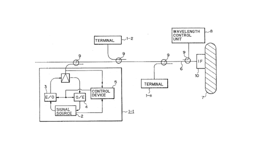
reference numerals 1~ 2, - - - , 1-n designate terminals.
Each of the terminals includes a signal source 2, a light
source 3 capable of controlling an oscillation wavelength,
a receiving circuit 4 capable of selecting a wavelength
and a control device 5. The reference numeral 6 designates
a wavelength-multiplex communication path (only one path
is shown in the figure); 7 a network accommodating the
wavelength-multiplex communication paths; 8 a wavelength
control unit serving for the entire communication paths;
9 a photocoupler; and lO an interface for interconnecting
wavelength-multiplex communication path 6 and network 7.
Operation of the optical communication system
will next be explained. When communication is required.
for example, from terminal 1-1 to network 7 through
2068252
wavelength-multiplex communication path 6, terminal 1-1
sends a transmission request to wavelength control unit 8
through control device 5 within terminal 1-1. A call from
control device 5 in terminal 1-1 to wavelength control unit
8 is made by means of the CSMA/CD method, the token passing
method, the TDMA method or the like. The transmission
request is carried through a control channel. The control
channel may be wavelength-multiplexed on communication path
6, or a physical line separate from the communication path,
may be provided for control purpose. Wavelength control unit
8 monitors the wavelengths being used in wavelength-multiplex
communication path 6 to which terminal 1-1 belongs to,
and selects a wavelength which is not overlapped with the
wavelengths being used on communication path 6 and informs
control device 5 in terminal 1-1 of the unused wavelength
via the control channel. Control device 5 in terminal 1-1
causes the oscillation wavelength of light source 3 to be
adjusted to the wavelength instructed by wavelength control
unit 8 so as to connect terminal 1-1 with network 7 via
wavelength-multiplex communication path 6 and interface 10.
Interface 10 connecting network 7 with wavelength-multiplex
communication paths 6 so controls that used wavelengths
may not be overlapped in order to avoid any interference
between different optical signals flowing through different
communication paths. Reception wavelength is, like the
transmission operation, set to receiving circuit 4 by control
device 5 in accordance with the instructions from wavelength
control unit 8 whereby reception is enabled. The wavelength
-- 10 --
20682~2
for transmission may be identical to or different from the
wavelength for reception. In this way, two terminals and
the network are interconnected by adjusting the transmission
wavelength and the reception wavelength to the instructed
wavelength(s).
In the above-described embodiment, a wavelength to
be assigned to terminal 1-1 is determined in accordance
with the wavelengths being used in a wavelength-multiplex
communication path. It is also possible to determine a
wavelength to be assigned to a caller by referring to the
wavelengths assigned to wavelength-multiplex communication
paths contained in one system.
An embodiment of a star-type communication network
will next be described.
In Fig. 5, when terminal 1-1 requests to be connected
to terminal 1-2, terminal 1-1 sends a connection request
to wavelength control unit 8 at a control wavelength.
Wavelength control unit 8 decides whether terminal 1-2 at
the other end is available for communication. If available,
wavelength control unit 8 informs terminal 1-1 and terminal
1-2 of an unused wavelength using the control wavelength
such that the used wavelengths may not be overlapped in star
coupler 9' serving as a part of the wavelength-multiplex
communication path. Control circuit 8-1 in wavelength
control unit 8 manages wavelengths in use and the operation
of the respective terminals. Terminal 1-1 and terminal 1-2
receive a signal from control circuit 8-1 in wavelength
control unit 8 by means of receiving circuits 5-1, 5-2 which
2068252
have been adJusted to the control wavelength, and adjust
transmission and reception wavelengths to the wavelength
indicated by the control wavelength, whereby the terminals at
both ends may be connected. The reference numerals 2-1, 2-2
designate signal sources; 3-1, 3-2, 3-8 light sources adapted
to convert electrical signals to corresponding optical
signals to be transmitted; and 5-1, 5-2, 5-8 receiving
circuits for converting optical signals to corresponding
electrical signals.
As explained above, the present invention is so
structured that a wavelength control unit assigns used
wavelengths to terminals in accordance with the wavelengths
already used in wavelength-multiplex communication path.
Accordingly, wavelengths may be effectively utilized and a
tree-network may be constructed. Also, additional terminals
may be easily attached to communication paths.
A concrete example of the optical communication system
according to the present invention is a wavelength-sharing
optical exchange system, which will now be described.
Fig. 6 is a block diagram illustrating an entire
structure of a wavelength-sharing optical exchange system
according to the present invention. In Fig. 6, the reference
numerals la through ld designate terminals; 2a through 2d
subscriber-like control units; 300 an optical switchboard;
400 an optical switch unit; 500 a network channel control
unit; 600 a coupler; and 101 through 104 wavelength-multiplex
communication paths.
- 12 -
2068252
Fig. 7 illustrate in detail subscriber-line control
units 2a through 2d, network channel control unit 500
and wavelength-multiplex communication paths and how they
are interconnected. In Fig. 7, the reference numeral 21
designates a photoelectric converter for converting an
optical signal of a control wavelength ~c to an electric
signal; 22 a laser diode (hereinafter called an LD) for
transmitting control wavelength ~c in accordance with an
electric signal; 23 a control section; 51 a switch control
section; 52 a wavelength table for storing the wavelengths
used in the switching network; and 53 a communication control
section for executing communication control between the
respective terminals and network channel control unit 500.
It is to be noted here that each of wavelength-multiplex
communication paths 101 and 103 is consisted of upward
wavelength-multiplex communication paths lOla, 103a carrying
signals to optical switchboard 300 and downward wavelength-
multiplex communication paths lOlb and 103b carrying signals
from optical switchboard 300. Other wavelength-multiplex
communication paths 102, 104 are also similarly constituted.
Operation of the optical exchange system will next be
described with reference to Figs. 6 and 7. When terminal la
requests communication with terminal lc, terminal la first
sends a call request at control wavelength ~c through
wavelength-multiplex communication path lOla to terminal lc.
Control wavelength ~c is directed via coupler 600 to
photoelectric converter 21 within subscriber-line control
unit 2a. Subscriber-line control unit 2a can detect a call
- 13 -
2068252
sent from any one of the terminals connected to wavelength-
multiplex communication path 101 by the TDMA method, the
CDMA/CD method, the token passing method or the like. Upon
receipt of a connection request from terminal la, subscriber-
line control unit 2a sends the request to network channelcontrol unit 500. Network channel control unit 500 decides
whether terminal lc at the other end is available for
communication by retrieving wavelength table 52. If terminal
lb is available for communication, communication control
section 53 instructs switch control section 51 to assign a
wavelength to terminal la and establish a communication path
in optical switch unit 400. Switch control section 51 (1)
looks through wavelength table 52 to find a wavelength unused
in the exchange network, or, in both wavelength-multiplex
communication paths 101 and 103, (2) selects, out of the
unused wavelengths, a wavelength ~x to be assigned to the
call, (3) causes wavelength table 52 to store information
relating to assigned wavelength ~x and the channel used, (4)
informs communication control section 53 of wavelength ~x,
and (5) causes optical switch unit 400 to establish
communication paths from wavelength-multiplex communication
paths lOla to wavelength-multiplex communication path 103b as
well as from wavelength-multiplex communication path 103a to
wavelength-multiplex communication path lOlb. Communication
control section 53 informs control sections 23 contained
in subscriber-like control units 2a and 2c of assigned
wavelength ~x and the used channel. Control sections 23
in units 2a and 2c inform terminals la and lc of assigned
2068252
wavelength ~x via wavelength-multiplex communication paths
lOlb and 103b, respectively, at control wavelength ~c using
laser diodes 22. Terminals la and lc set transmission and
reception wavelengths to wavelength ~x informed through
control wavelength ~c and commence communication. When
communication is finished and the call is interrupted.
the content recorded in wavelength table 52 is erased.
Fig. 8 illustrates the structure of optical switch
unit 400. Wavelength signals which come from wavelength-
multiplex communication paths lOla and 103a are shown to beswitched to wavelength-multiplex communication paths 103b and
lOlb. The reference numeral 40 designates a cross point, the
structure of which is shown in detail in Fig. 9. An optical
signal branched from wavelength-multiplex communication path
lOla by a branch device 33 is further branched by a branch
device 41 and passes through wavelength filters 43 controlled
by switch control signals 106 and each corresponding to the
wavelengths to be switched. The optical signals are then
wavelength-multiplexed by a combining device 42 and coupled
to wavelength-multiplex communication path 103b by a
combining device 31.
Fig. 10 illustrate an interface unit provided at
each of terminals la through ld. In Fig. 10, the reference
numeral 12 designates a wavelength-variable LD; 13 a
wavelength control section; 14 a wavelength-variable filter;
15 a branch device; 16 and 19 wavelength monitors; 17 a
photoelectric converter; and 18 a wavelength setting section.
When a call is made, wavelength control section 13 causes, in
- 15 -
2068252
response to a call signal 108, the wavelength of wavelength-
variable LD 12 to be set to control wavelength ~c, thereby
enabling the call by using wavelength ~c. Wavelength-
variable filter 14 is set to control wavelength ~c so that
the filter can receive signal at any time except the period
of communication. When information about wavelength ~x used
for communication with the terminal at the other end and
designated by optical switchboard 300 is received, the
wavelength information is supplied via wavelength-variable
filter 14 to photoelectric converter 17 which converts the
information to an electric signal and feeds it to wavelength
setting section 18. Wavelength setting section 18 instructs
wavelength control section 13 to set a communication
wavelength to ~x based on the wavelength information.
Wavelength control section 13 supplies control signals
which serve to set the wavelength of light emitted by
wavelength-variable LD 12 and the wavelength passable
through wavelength-variable filter 14 to ~x. Wavelength
monitors 16, 19 operate to monitor the reception wavelength
and the transmission wavelength and control wavelength
control section 13 through feed back loops so as to
avoid deviation in wavelength. When the communication is
terminated and the call is interrupted, wavelength control
section 13 resets wavelength-variable filter 14 so as to
be able to receive control wavelength ~c.
Fig. 11 schematically shows an optical switch
unit 400. In this figure, the reference numeral 30
designates a unit switch; lOla (103a) and 102a (104a)
2068252
wavelength-multiplex communication paths carrying signals
to optical switchboard 300; 103b (lOlb) and 104b (102b)
wavelength-multiplex communication paths carrying signals
from optical switchboard 300; and 31 a combining device.
Unit switch 30 functions to take an optical signal of an
arbitrary wavelength out of the optical signals passing
through one wavelength-multiplex communication path to
another optical wavelength-multiplex communication path
such that the optical signals of the remaining wavelengths
may not be lost from the wavelength-multiplex communication
path.
Fig. 12 illustrates another example of optical switch
unit 400. In this figure, an optical signal branched from
a wavelength-multiplex communication path to one of the
output lines of branch device 33 is separated to optical
signals of respective wavelengths by a separator 38. The
optical signals of the respective wavelengths are output from
separator 38 to predetermined output lines. The outputs of
separator 38 are spatially exchanged by an mx2m matrix switch
39. Signals on m output lines are wavelength-multiplexed by
a combining device 42 and output to the wavelength-multiplex
communication path through combining device 31. The
remaining signals, which are not output to the wavelength-
multiplex communication path, are discarded through the
remaining m output lines. The other output line of branch
device 33 includes the optical signals of all the wavelengths
and sent to the subsequent unit switch. Switching is
20682S2
executed by electrically controlling matrix switch 39 and
control is performed by network channel control unit 500.
Fig. 13 illustrates a further example of optical
switch unit 400. In this figure, optical signals ~1 through
~m supplied from wavelength-multiplex communication paths
101a through 10na and separated to respective wavelengths
by separators 381 through 38n enter matrix switches 391
through 39m provided for the respective wavelengths. Each
of matrix switches 391 through 39m outputs n signals each
having the same wavelength. Combining devices 311 through
31n receive signals having wavelengths ~ m and multiplex
and output the received signals to output lines 101b - 10nb.
Distribution of the respective wavelength signals is executed
by matrix switches 391 through 39m.
Although, in the above-described example, m spatial
switches are required, it is possible to provide only one
switch 39, as shown in Fig. 14.
Fig. 15 illustrates a still another example of optical
switch unit 400. Optical signals ~1 through ~m supplied from
wavelength-multiplex communication path 101a and separated
to respective wavelengths by separator 38 are passed to
communication paths 451 through 45m corresponding to the
respective wavelengths. Respective communication paths 451
through 45m each include lX2 switches 46, and combining
devices 31 are provided at crossing points with output
wavelength-multiplex communication path 103b. An optical
signal selected by lX2 switch 46 is wavelength-multiplexed
at wavelength-multiplex communication path 103b by
- 18 -
2068252
combining device 31. Each optical signal is distributed
by lx2 switch 46.
As explained above, according to a wavelength-sharing
optical exchange system of the present invention, a wave-
length to be used is assigned to a call by network channelcontrol unit in accordance with the status of the exchange
network at the time the call is placed. Accordingly, no
wavelength conversion is required and more terminals than
the number of wavelengths can be connected, resulting in
effective utilization of wavelength.
Furthermore, since an optical switch unit can be
formed by waveguide-type components, a stable performance
may be attained.
-- 19 --