Note: Descriptions are shown in the official language in which they were submitted.
2068~20
CONTROLLED SLEW RATE AMPLIFIER
Technical Field
This invention relates generally to linear amplifier
circuits. In particular, this invention relates to negative
feedback linear amplifier circuits that adjust input
signal levels to maximize output power and efficiency
15 while preventing output signal distortion caused by over
driving the amplifier stage.
Background of the Invention
Electronic amplifier circuits are well known in the
art. These devices employ various techniques to improve
their linearity. There is often a need to maximize output
power and efficiency of a linear amplifier circuit by
providing sufficient input drive signal levels. However,
with any given amplifier there is a drive level beyond
which linearity is severely degraded. When overdriven
by an input signal most amplifier circuits will
inherently generate undesired signals as either adjacent
channel frequency splatter or other unwanted signals.
Electronic amplifier circuits that run in Class B or
AB are desirable because of their relatively high
efficiency and are somewhat linear but require negative
2068420
....
feedback to obtain the improved linearity demanded by
many applications. Reducing output signal distortion or
frequency splatter in a class B or class AB amplifier
might permit use of these amplifiers in communications
5 applications requiring relatively distortion-free
amplification. Negative feedback reduces distortion as
long as the amplifier is not overdriven. Since negative
feedback actually increases distortion and unwanted
signals when the amplifier is overdriven, it is important
10 to prevent a~ amplifier from being overdriven.
In many communications applications, adjacent
channel frequency splatter caused by an overdriven final
amplifier stage in a radio transmitter causes
undesirable interference with adjacent channel users. In
15 such applications, which may be typically employed in
digital or analog communications systems using signals
with a time-varying amplitude, a test signal might be
used to determine the maximum allowable input level to
the final amplifier stage in order to prevent the final
20 amplifier from being overdriven. In instances where an
input test sequence is used to determine the maximum
input level to an amplifier, even the input test ssquence
may cause undesirable adjacent frequency splatter at
the instant that the amplifier's maximum drive level has
25 been reached.
As an input signal to an amplifier increases in
amplitude, an ideal output amplifier circuit would track
changes in the input level and amplify the input level
producing a substantially exact copy of the input signal.
30 Practical limitations of an electronic amplifier limit
the ability of a circuit to infinitely follow input signal
levels. As an input signal level increases to the point
2 C~00611 G
2068~20
..~
where the output amplifier stage can no longer amplify
it accurately, the output stage will begin to saturate
and, if the amplifier's output signal is fed back to the
input in a negative feedback loop, an algebraic addition
5 of the amplifier's input signal with its feedback error
signal, can produce substantial distortion in the signal
input to the amplifier stage.
In some communications applications, it may be
desirable to limit the amount of frequency splatter
10 caused by overdriving an amplifier, even during inteNals
when the maximum input level for the amplifier is being
determined by a test sequence. An amplifier circuit that
includes the ability to limit adjacent frequency splatter
even when a maximum drive level is being measured by a
15 test sequence would be an improvement over the prior
art.
Summary of the Invention
There is provided herein an amplifier circuit that
reduces off-channel frequency splatter caused by
excessive input signal levels, including off-channel
splatter caused by input test signals used to established
maximum input signal levels. The amplifier circuit in
the preferred embodiment is comprised of an inverting
amplifier stage, a feedback circuit that samples the
output of the amplifier and couples a portion of the
output signal back to the amplifiers input, and an
adjustable slew rate amplifier coupled between the
amplifier stage input and the input signal source, the
slew rate of which is reduced during periods when input
level test sequences are input to the amplifier circuit.
3 C~00611 G
2068120
(The test sequences are typically slow rise-time signals
or voltage ramps used to establish a maximum input
level.)
The adjustable slew rate amplifier has its slew
s rate limited, or controlled, during periods when a test
signal is being input to the amplifier stage to determine
the maximum input signal level which the amplifier
stage can accept without clipping. The adjustable slew
rate amplifier reduces off-channel splatter from the
amplifier caused by its being overdriven by the test
sequences by virtue of its ability to suppress signals
being input to the amplifier that exceed the amplifiers
ability to follow the rise time of the signals.
At least two different slew rates are established
under the control of an external circuit. In an
operational mode the slew rate amplifier has a maximum
slew rate that is capable of accurately tracking the rise
time of input signal levels experienced under normal
operating conditions. In its limited slew rate mode,
entered when input test signals that have typically slow
rise times are being input to the amplifier, the reduced
slew rate of the amplifier is sufficient to follow the
input test signal but is suppresses undesirable emission
from the amplifier when overdrive occurs.
Brief Description of the Drawings
FIG. 1 shows a block diagram of an amplifier
circuit providing reduced off-channel frequency splatter;
FIG. 2 shows a block diagram of an amplifier
providing reduced off-channel frequency splatter for use
with quadrature amplitude signals; and
4 C~00611 G
2068420
~,
FIG. 3 shows a schematic diagram of an adjustable
slew rate amplifier contemplated in FIG. 1 and FIG. 2.
Detailed Description of the Preferred Embodiment
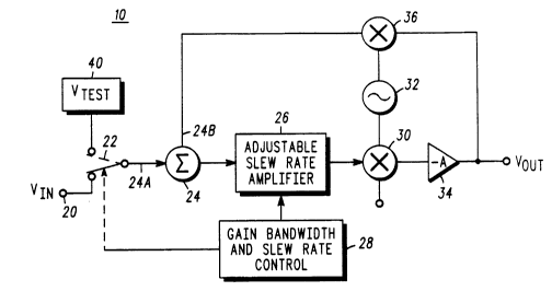
FIG. 1 shows a simplified block diagram of an
amplifier circuit (10) that provides reduced off-
fraquency splatter that may be caused by clip detection
sequences input to an amplifier to determine its
maximum allowable drive level. In the amplifier circuit
(10) shown in FIG. 1, an input signal (20) from an
external source, such as an audio modulator or other
source is coupled to a first input (24A) of a summing
network (24) through a selection switch (22) The output
of the summer (24) is coupled to an adjustable slew rate
amplifier (26) which, in its normal operational mode,
has a maximum slew rate sufficient to accommodate the
rise time of the signals from the signal source (20).
As seen in FIG. 1, the output of the adjustable slew
rate amplifier (26) is coupled to a first multiplier, (also
known as a mixer and which in FIG. 1 is a two-input
mixer) circuit (30), the other input of which is coupled
to the output of a local oscillator (32) (not shown). The
multiplier circuit (30) mixes or heterodynes the output
of the adjustable slew rate amplifier to a frequency
equal to the sum (or difference depending upon the
desired product frequency) of the local oscillator
frequency and the frequency of the output of the
adjustable slew rate amplifier (26).
The output of the multiplier circuit (30) is
amplified by an inverting amplifier stage (34) to produce
an output voltage Vout. The output signal of the
C~00611 G
20~8~0
..,
inverting amplifier stage (34) might be coupled to an
antenna, for example; it might also be coupled to
subsequent signal processing stages as required by the
- particular application considered for the amplifier
5 circuit (10).
In the amplifier circuit shown in FIG. 1, the output
of the inverting amplifier stage (34) is coupled to a
second multiplier, stage (36) (also known as a mixer)
the other input of which receives the local oscillator
10 signal (32). The second multiplier stage (36)
heterodynes the output of the inverting amplifier stage
(34) by the same local oscillator signal from the local
oscillator (32) to produce the baseband signal input to
the adjustable slew rate amplifier (26) from the
15 summing node (24). The output of the second multiplier
stage (36) is coupled to the second input (24B) of the
summing network (24).
(The embodiment shown contemplates being used in
a radio. Alternate embodiments of the invention might
20 not use the single frequency conversion shown in FIG. 1
but might use multiple conversion. Still other
embodiments of the invention might not use any
frequency conversion in the amplifier circuit shown and
perform essentially all functions at a single frequency,
25 b~seb~nd for example.)
The summing network (24) produces at an output, a
signal that is substantially the algebraic sum of the
first input (24A) and the second input (24B). Since the
final amplifier stage (34) is an inverting amplifier, the
30 algebraic addition of the signal at input (24A) and the
addition of the signal (24B) produces as a net result, a
subtraction of these two signals. The output from the
6 C~00611 G
2068~20
summer (24) can be thought of as an error signal which
is amplified by the adjustable slew rate amplifier (26).
If the input signal to the adjustable slew rate amplifier
(26) has a slew rate or rise time that exceeds the ability
5 of the adjustable slew rate amplifier to follow it, the
adjustable slew rate amplifier will limit the slew rate
time of the signal input to the first multiplier (30)t to
the maximum slew rate capability of the slew rate
amplifier.
The maximum slew rate of the adjustable slew
rate amplifier (26) is substantially reduced under the
control of the gain bandwidth and slew rate control
circuit (28) during times when a test signal from a test
signal source (40) is switched into the summing network
15 (24) by means of the source selector switch (22). The
test signal is used to establish the maximum input level
that the amplifier circuit (10) can accept at the first
input (24A) of the summing network (24).
The maximum input signal level that the amplifier
20 circuit (10) can accurately reproduce can be determined
by putting a slow rise time signal from the test signal
source (40) that increases slowly to a point at which the
output from the inverting amplifier stage (34) begins to
saturate or clip. When this maximum input signal level
25 is reached, its determination can thereafter be used to
limit input signal excursion from the signal source (20)
to eliminate distortion or splatter caused by overdriviing
the amplifier stage (34).
During the time that the test signal from the test
30 signal source (40) is being input to the summing network
(24) adjacent or off-channel frequency splatter caused
by clipping of the amplifier can be avoided by reducing
7 C~00611 G
2068~20
~ .
the slew rate of the adjustable slew rate amplifier (26).
Adding the adjustable slew rate amplifier and reducing
its slew rate during instances when the input drive level
are being measured virtually precludes the generation of
5 any off-channel frequency splatter, even during input
test sequences to the amplifier, which can cause
clipping. In this manner very clear signal sources can be
maintained in communication systems that require
minimal adjacent channel interference.
FIG. 2 shows a block diagram of another application
of the preferred embodiment of the amplifier circuit
that reduces off-channel frequency splatter, including
off-channel frequency splatter caused by clip detection
sequences. In this figure the amplifier circuit, a so-
15 called quadrature amplifier, amplifies an in-phase
component designated as l-channel as well as a
quadrature component designated as Q-channel. (The I
and Q signal components are baseband signals, which are
used to scale the magnitudes of local oscillator signals
20 that are ninety degrees apart from each other. The I and
Q signals as well as the phase or frequency of the local
oscillator can be used to carry information.)
In this figure, a digital signal processor controls
digital to analog convertors 501 and 50Q, respectively,
25 that generate the input information signals for a
communications device such-as a radio transmitter. The
output of the digital to analog convertors 501 and 50Q
are both low-pass-filtered in I channel and Q channel
low pass filters 421 and 42Q. The output of the low
30 pass filters for the I channels and Q channels are both
input to I channel and Q channel summing circuits 241
and 24Q respectively. The output of these summing
8 C~00611 G
20S8420
.~ g
circuits are coupled to I channel and Q channel
- adjustable slew rate amplifier circuits (261 and 26Q) .
Both of these adjustable slew rate amplifiers (261 and
26Q) are controlled by a gain bandwidth slew rate
5 control circuit (28) not shown in Fig. 2. (The slew rate
control circuit (28) might include a microprocessor or
other circuitry capable of determining when the slew
rate of the adjustable slew rate amplifiers is to be
reduced.)
As shown in FIG. 1, the output of these adjustable
slew rate amplifiers (261 and 26Q) are both coupled into
multiplier circuits (301 and 30Q). These two multiplier
circuits both obtain their heterodyning frequencies from
a local oscillator (32) (not shown in Fig. 2) the
15 quadrature or Q component of which is generated by
phase shifting the local oscillator signal by ninety
degrees in a phase shifting network (33).
The output of both the I channel and Q channel
multiplier circuits (301 and 30Q) are summed in a
20 summing network (35) the output of which is amplified
by the final amplifier stage (34), similar to the
implementation shown in FIG. 1.
In FIG. 2 the output of the final amplifier stage
(34) is sampled and returned to two multiplier circuits
25 (361 and 36Q) which restore the output of the final
amplifier stage (34) to baseband frequencies by
multiplying the amplifier output signals by a second
local oscillator signal 32P that has been phase shifted
from the local oscillator signal 32 for loop stability
30 (one copy of signal 32P is also phase shifted by 90
degrees to return the Q channel component back to
b~seb~nd). The negative feedb~ck loop of the quadrature
9 C~0061 1 G
2068~20
amplifier is completed by connecting the fedback signals
from the multipliers (361 and 36Q) to the second inputs
of the I channel and Q channel first summers (241 and
24Q).
In communications applications that require multi-
level QAM or quadrature amplitude modulation signals, or
other variable amplitude signals, such as single
sideband, the amplifier circuit shown in FIG. 2 can
reduce off-channel frequency splatter even caused by
clip detection sequences as described above. When a clip
detection sequence is input at summing networks 241
and 24Q, which test sequence is typically comprised of a
slow rise time ramp voltage, the slew rate of the
adjustable amplifiers (261 and 26Q) is reduced to
suppress the generation of harmonics or spurious signals
caused by a test sequence that rises beyond the point at
which the final amplifier stage (34) can accurately
amplify it.
An adjustable slew rate amplifier used in FlGs. 1
and 2 is shown in FIG. 3. The adjustable slew rate
amplifier (26) may be considered as a voltage to current
convertor or a transconductance amplifier, the output of
which is shunted by an RC network.
Slew rate adjustment is achieved by means of
adjusting the tail current I through the constant current
source transistor Qs. Q1 and Q2 form a differential pair.
Q3 and Q4 form a current mirror to provide an active load
for the collectors of Q1 and Q2. If the collector current
through Qs is established to be relatively large, both Q1
and Q2 may conduct fairly heavily through Q3, Q4,
respectively. (RE1 and RE2 may be selected to limit the
CM4061 1G
2068420
1 1
amount of collector current and increase the output
impedance of the active load.)
When the collector current (I) through Qs is
relatively large the voltage swing on the inverting and
5 non-inverting terminals VIN- and VIN+ may swing
relatively freely with the resultant output current at the
collectors of Q4 and Q2 swinging between -I and ,I where
I is the value of current through Os. As the rate of change
of output voltage across the capacitor is equal to 1/C
10 times the current through the capacitor, a relatively
large collector current through Qs will permit the output
voltage across the c~p~citor Co to change very quickly.
If the collector current I through Qs is made
relatively small, the maximum rate of change of the
15 output voltage, also known as the slew rate, will also be
small, regardless of the input signal excursion across
the bases of Q1 and Q2-
It should be seen that an adjustable slew rateamplifier has been shown which when incorporated into
20 a signal loop of an amplifier stage can be used to reduce
~dj^cent channel frequency splatter when the maximum
input level signals that the amplifier can amplify is
being measured during test signals. In this fashion, even
test sequence frequency splatter can be reduced further
25 improving or reducing off-channel interference in radio
communication systems that require precise splatter
control.
Although an inverting amplifier is shown in Fig.1,
alternate embodiments might include using a non-
30 inverting gain stage for the amplifier (34). Using a non-
inverting amplifier would thereafter require using some
other signal inversion means, such as an inverting
11 CM~0611G
2068420
.~
12
voltage amplifier or inverting operational amplifier,
between the output of the amplifier (34) and the second
input (24B) of the summer (24) so as to produce a
difference signal output from the summer (24).
5 Furthermore, the amplifier (34) need not provide voltage
amplification but might provide current gain if an
appropriate output load is selected. Alternate
embodiments might also contemplate using a voltage or
current follower as the final amplifier (34) so long as a
10 negative feedback signal is provided to the summer
circuits (24, or 241 and 24C~).
What is claimed is:
12 CM4061 1 G