Note: Descriptions are shown in the official language in which they were submitted.
W~) 91/07587 PCl'/HU90/01)072
a .~
20~717
WATER CURRENT ENERGY CONVERTER
Field and Background of the Invention
~he present invention relate~ to a ~ater current ener~y
converter designed for and capable of convertin~ the flow
ener~y of a moving body of water into electric power~ such
converter comprisinQ at least one ~ater driven ~low machine,
especially a water turbin~e, an electric poller ~enerator, and
a hydraulic ener~y transer system arranged between said
water turbine(s) and said power ~enerator.
~he known types o~ contemporary hydroelectric ~aohines . .
for ~eneratin~ eletric~pow.er by makin~ use of the flo~l
energy of movin~ bodies of water embody the different types
of water driven turbines that have been developed to
hi~hly sophisticated technical standard. ~!ith hitherto known
` such ~achines, ~aintainin~ a constant speed of revolution
of.the water driven turbines used for power neneration is
a primary requiremen-t. ~he maintenance of constant speed can
be effected by continuously adjusting, during operation,
; .either the blade an~le~of the turbine propellqr blade5, or
the wheel dischar~e of the turbine, the latter usually
performed by turbine ~ate ri~ing, i.e. by continuously
altering the position o~ baffle plates arran~ed within the
inlet ~rea of the turbine wheel passa~e. Both ways of.speed
¢ontrol ~entioned reqùire elabora.e and thus) expensive
~achinery with inherent tendunoy to operation failures, snd
lso~with lossés o~ e.~iciency involved. ~ . ;
.. .. . . . . .
~Another teohnical problem lies In the fact that an
A.C. voltage of th2 frequenc~ ranne between 50 to 54 Hz
~sually required ~or industrial purpDses can only be penerated
- . ~
S~BSTITU ~ E ~
w09l/07587 PCT/HU90/00072
~ 2 -
by water driven turbine5 ~f ~ rated speed of 100 to 600
revolutions per minute ~ sn electric power yenerator of
cDnsiderable size, i.e. diameter i5 coupled to the turbine
shaft. Alternatively, ~ ~enerator of reduced diameter should
be driven by the water turbine via ~ speed reducing ~ear
whereby mechanical efficiency i5 reduced by simultaneous
increase of investment and maintenance expenditures. For the
sake of exa~ple only, reference i5 made to an existin~ power
plant situated at the ~outh of the river RoncP in France
where an electrio power ~eneratnr of the diameter of 4 metres
is driven by an adjustable blade Kaplan-type turbine having
an impeller of the diameter of 5.35 metres ~nd operatin~ at
a ~ated speed of 93.75 revolutions per minute. Such and
similar large size equipment can economically be us~d in
connection ~ith hu~e dams or weirs only. Such types of
~achinery ~re, however, completely excluded from possible
use in all cases where the u~ilization of the energy of
water flow, especially ~idal currents of oniy 1 to 2 or even
4 to 5 metres in thickness of layer, ~nd o~ up to 40 km pzr
hour speed of advance is envisaged.
~ ater currents of such characteristics are occasionally
several thousand metres wlde and their e5timated total energy
content could be a ~ultiple of that of the famous Nia~ara
Falls, According to both, local observations ~nd ~ea,sured
values, on the river Amasonas heavy break-ins of tidal current
in form of sn advancing wall-like tidal surge speeding up to
4d km per hour ~gainst the river stream ~nd havin~ a height
of 4.5 ~etres by ~ ~idth o~ 12 km are quite common at t~mes
of sun-moon con~unction, Sources of literature re~er to
tidal sur~es observed at the ~outh of the river Humber that
occure twice a day ~ith a flow speed up to 40 km per hour.
Irl a distance of 10 km furthe~ upstream form the ~outh, the
height of the tidal vawe oould still be e~timated to 2 ~etres.
Similarly to ~his, the speed of the tidal current through
the mouth cf the river Seine has slso been Ineasured to 40 km
~:
.
SlJ~ 1TUlTE ~;H~ET
`
wosl/o7~7 PcT/Huso/ooo7~
2~87~
per hour, ~nd its hei~htCan als~ reach 2 metres. In certain
areas between sea ~slands ~nd in narrows tidal currents of
higher speed than,those mentioned above invDlving extremely
huge masses of ~ater have also been located. It is a well
known experience to those familar with navigation that in
certain periods of flood tide, car~o vessels of minor or
even average performance have their ~ifficulty o~ passing
the Straits of Gibraltar.,
Summary and Objects of the Inventlon
An object of the present invention is to provide an
apparatus for capturin~ the ener~y contents of water currents
of relatively lo~l, e.Q. of ar~und one metre thickness of
iayer and of chan~in~ levelA The apparatus accordin~ to the
invention should bP capahle of utilizin~ the energy of
currents present in bodies of surface waters such as currents
of rivers'of even s~all cross section but relatively high .
speed of flow, tidal currents, currents o~ different types of
advancing vawes like flood va~es and other similar water body
~ovements, Another object o,f the invention is to provide an .'
apparatus which makes use of 1the enerQy o~ such bodies of
water at relatively lo~ investment and operational costs, and
~Ihich is able to turn it in~o work producin~ form with high
efficiency.
The above and other objects will be solved by a water
currènt ~ner~y converter of the above-noted type in which
at least one thoroughfare..'flow duct o~ a bunyant bDdy ~t least
one pumping unit compri~i'ng a`hydraùllc rotary pump coupled
to'~a shaft of a water driven turbine is provided. The buoyant
body is held:by~suitable anchoring ~eans in a pre-deter~ined
orientation and in a suhstantially stationary position in a
movins 5ur~ace ~Jater, pre~erably in a near-to-shore area o~
a'sea or lake, or.the~mouth of a river so that it is allowed
to free`ly follow ohanges i.e. the rise and fall o~ the surface
water level, The at least one.thoroughfare flow duct is
~rovided in a suhstantially bottom part of the buoyant body ,.
so that it is constantly a'nd entireiy under the water level
.` ' ~.' i ~ g g.i~ ~ b'. ~ r
.. , ,. . , . ;. . ; .
W O 91/07~87 . PC~r/H U90/00072
(.r , "
~Q`~ 4
i.e. immersed in water when the buoyant body is in its
floating, anohored position of operation. The hydraulic
rotary pump forms component part and serves as hydraulie
pressure source in a hydraulic energy transfer system that
comprises, among other parts, a hydroengine that is drivingly
coupled to a power generator which, together with the pumping
unit and the whole hydraulic energy transfer system is located
within the buoyant body.
In preferred embodiments of the invention the buoyant
body is a subs~antially rigid thin-shell structure of stream-
lined, elongate shape when vie~led in a direction that is
co-axial with the at least one thoroughfare flow duct. Its '
shape is further mirror symmetrical to cross sections taken
through the buoyant ~ody along both a longitudInal and a
transverse vertical imaginary plane. The buoyant body has
fastening portions, preferably four in number that are suitabie
fbr being connected to the anchorin~ means and are arranged
pairwise on'both sides and equally distanced from both ends
of the buoyant body. The above arran~ement of the fastening
portions ensures that the pre-determined orientation of the
buoyant body remains maintained even in the case if one of
the ~ ~aur anchoring means (which can be provided by any
suitable rope, chaine or cable) ceases to withstand load and
dynamic stress. The arrangement of the ~astening portions
together w.lth the streamlined shape o~ the buoyant body
further results 'in an increased excellent resistivity of the
buoyant body and thus, oi the ener~y converteragainst wind
loa'd and ~hocks that are exercised by'masses of water splashing
against sald body under stormy weather conditions.
'' In further preferr0d embodiments of the invention the
buoyant bo~ly is à shape-retentive thin-shell structure
substantially made of preferably reinforced synthetic resin.
'It comprises a~ its bottom a lon~itudin'al keel o~ convex
U-shape, at both sides along the bottom of its end portions
a pair of thinner longitudinal ribs oi oonvex U-shape, on its
' ~
,""", ''.'''"" " ',' ' ~' '` '- " i",, ~. ', ' ~", . .'' ,
,, ' ' : ' . ' . : . ' ' , ' ,:
WO 91/07587 PCI`/HU90/00072
2~6~17
upper side ~t b~th ends respective deck lids of substantially
streamline~ shape, snd a remnvable cover ~et~leen the de~k
lids. ~he latter is, along its matchin~ edges, hermetically
~oinable to matching surfaces of the buoyant body. Resulting
from the above characteristic features, the present invention
provides a substantially rigid housing for the floatino energy
converter. Said housing is of high durability and enables
easy ~cces to all fuctional component parts of the converter
especially f~ar service and maintenance purposes. Such buoyant
bodies arP relatively easy to manufacture by using well-known
techniques.
Xn 5cill further preferred embodiments of the
invention each thorouoh~are flow.duct consists of a
suhstantiall~;! cyl~ndrical middle ~uct section laid out for
and capable ~f housing the pumping units, and of adjoinin~,
identically ~haped outer duct sections that are of hroadenin~
cross section towards in - or outlet openings of the flow
duct. Such in- or outlet openings are arranQed, respectively,
at opposlte ends of the elon~ate buoyant body. Such preferred
embodiments make use of ~he well-known principle of using diffu-
~er 3nd confuser sections in ~low channels of turbines for
better current energy utilization.
In embodiments of the pre~nt invention the
substantially cylindrical middle duct section of the flow
dur,t preferably comprises a tubular steel house for fastenin~
~nd holding the pumping unit. The tubular s~eel house may~
atlleast in preferred embodimentsl be a steel ~tructure
consistin~ of a pair of ~atching haiE-cylindric tube portions.
Such embodiments allow for easy ~ounting of and easy access
to the pumpinD units with simultaneouS increase af thq strength
~nd~ri~idity, From viewpoints of optimum cost and rated
performance per unit em'Jodiments provided with a pair of
thoroughfare flo~ ~ucts in parallel twinlike arran~ement
have proved to be an ~ptimum solution. In preferred further
embodi~entSof the invention the pumping units cf the ener~y
converter comprise a water driven turbine having sn impeller
ST~Tl 1TE SHE~
.
''';' '' ' ' ~''" ',.'' ,.', "'," " .'" . ' '.:' , . .' ' `
:, . . , . ~- . , . ,
. . . . ......... . . ...
- ... . ~, . . . . . .
WO 91/075~7 PCI /HU90/00072
6 -
with rigid, non-adjustable blades and a hydraulic rotary pu~p
that is drivingly coupled to the shaft of the impeller of
the water driven turbine. The hydraulic rotary pump is capable
o~ pumping and pressur~ang a suitable hydraulic fluid in
both senses of rotation. Such embodiments are of relatively
low investment cost and allow, when anchored and duly oriented
in surface water areas of alternating water current, for their
operation in both directions of ~Jater flow with identical
operational characteristics and efficiency.
For the sake of easy maintenance and repair, in
preferred embodiments of the invention the pumping units
are designed and constructed as modular units boilt in inter-
changeably in the substantially cylindrical mid,~le sections
of the thoroughfare flow ducts of the buoyant b~dy. Such
embodiments of the invention allow for regular maïntenance
by replàeing the pumping units at pre-determined regular
intervalls so that inspection and repair works can be performed
on shore and independently from normal operation.
As alr'eady mentioned further above, the wa-ter
curr~ent enërgy converter acc'ording to the present invention
also comprises a hydraulic energy transfer system which is
arranged between the water turbine~s) and the power generator.
With today's techniques, such hydraulic energy transfer
systems can be designed and realized in a lar~e number oP
different embodiments. The main object of this hydraulic energy
trans~er;system is to provide cnnstant and unl~orm aperational
characiteristics, especially pressure and flo~l rate of the '
hydraulic fluid, preferably hydraulic oil, for a hydro'engine
by which the power-generator of the energy con~erter is ~riven.
The operational characteristics mentioned should be maintained
independently from the c~laracteristicS o~ the water driven
turbines, such characteristics varying"in both,~sp'eed of
rotation and rated ~orque during operation.
In one preferred embodiment of the water current
energy 'converter according to the present invention the
' ' .
b ~ T". ~
:-: , ~ ............ : . : . . :
;, , ~, ,, , '' :', ' :
WO 91/07587 . PCI /H U90/0007
, ' I ...
' _ 7 _ 2 Q'~ 8 ~1 7
hydraulic energy transfer system comprises the hydrauli~
rotary pumps of the pumpin~ units, a delivery duct and a~
induction pipe. Both of them are, via a valve array, connected
to the hydraulic rotary pumps. ~he hydraulic energy transfer
system further ~omprises a safety relief valve, at least one
hydropneumatic pressure storage tank, a flow control valve
and a container for a suitab';e hydraulic ~luid, preferably
hydraulic oil. The at lzast one pressure storage'tank is
connected to a pressure tube leading from the safety relief
valve to an inlet o~ the flow control valve. An inlet OL the
safety relief ~alve is connested to the delivery duct, and
a first outlet of the flow control valve is connected to a -'
discharge pipe that supplies q controlled flow of the hydraulic
fluid to the hydroengine.'ThE container is connected to the
induction pipe, Vi2 a return line to a relief outlet of the
safety relief valve, through a return pipe to a second o~_
let of the flow control vllve, and through a collecting main
to an exhaust outlet of the hydroengine.
The valve ~rray mentianed above comprises a circuit
of flow actoated automatic check valves. rhe circuit is inserted
between joining nipples for supplying and discharging the
hydraulic fluid ~o and from the hydraulic rotary pumps on
one hand, and ~he delivery duct and the induction pipe on
the other hand. The valve arra'v is designed for and capable
of directin~ the ilow of the hydrau'lic flyid into thc delivery
duct ~rom the hydraulic rotary pumps in both senses o~ their
rotatiOn~
Brief Descrlptlon of'the Drawlng ' ^' ''
The invention will become'more readily apparent from'
the foilow'in~ description of a'preferred~em~od}nlent thereof
with rèference to''the accompanying drawing, in which:
: SUBSTlT~lrE '-1~3~E~ :
~, ,
.. . . . . . ..
. . . . . . . . . .. .. . . .
.. . ~ ' . . ~ ' ' .... .... . . . . ...
W091/07~S7 PCT/H~190/00~72
~ 8 - f~
Fig.l. is a simplifie~ sche~atic side view, partly
in section, of a pre~erred embo~iment of the
present invention, -
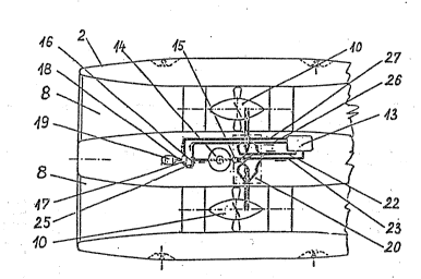
Fig.2. is a simplified schematic top view of the
embodi~ent shown in Fi~.l where deck lids
and cover of the upper side are removed,
Fi~.3. is a schematic end view of the embodiment
shown in Fi~s.l and 2,
Fi~.4. 'is a partial cross section of the buoyant
body o~ the embodiment taken in part along
a plane IV-IV as shown in Fig.l,
Fig.5, is a schematic block dia~ramm of the
hydraulic energy transfer syste~ cf the
emhodiment shown in Fi~s. l to 4, and
Figs 6 and 7 sh~w the arrangement of the ~unct'ional
component par-;s of the hydraulic energy
transfer system shown in Fig.5 in the
emhodiment of the ener~y converter
accordin~ to the present invention in
schematic side and top view, respectively.
'Description of the Preferred Embodiment
The attached drawing fi~ures illustrate a preferred
embodiment~of the water current energy conYerter according
to the;present invention. A buoyant body ~ having two
co-parallel thoroughfare flow ~ucts 8 in a twlnlike
,arran~emënt is held by four anchorin~ means l a'ttached to
~astenin~ portions 7 in pre-deterrnine~ orientation and i'n
a substantially stationary position in a surface water~
preferably in a near-to-shore area of a sea or a lake or ''
in the mouth of a river where substantially continuous or
alternatin~ water current i5 present. The four anchorin~
means l are preferably steel cables or chains ~hich allow
the ~loatin~ buoyant body 2 to freely follow changes`i.e. the
rise and fall o~ the sur.~ace water`level indicated hy reference
.
.. ... .. . .. . . . . . . .
:.~ ` . ; . ~ , .. . . . . .. . .. . . .
. , ., ,, , ~. , . ., ; ,. .,. '';, '
WO?1/07587 PCr/HU90/00072
' :- 9 ~ 7~
sign V shile it5 orientation is suhstantially maintained.
The buoyant body 2 is a substantially rigid thiu-shell structure
of strea~lined, elongate shape when viewed in centerline direction
of the flow ducts 8, and its elongate shape is mirror sy~metrical
to cross-sec~ions taken throu~h the huoyant body 2 along both
a longitudinal vertical imaginary plane U and a transversal
vertical imaginary plan~ T. The buoyant body 2 has altogether
four fastening portians 7 that are suitable for being connected .-
to the anchoring means 1 mentioned further abovt. The
~astening portions 7 are arranged pairwise on bcth sides and
equally distanced from both ends of the buoyant ~ody 2. According
to an important characteristic ~eature of the in~ention the
buoyant body 2 is ~haped andlaid out in a manner that it has,
when floating ready equipped and filled up for n-,rmal operation,
a flo ~tion line at which the thorou~hfare flow Jucts B are
~ully and entirely immersed in water.
In order to have sufficient load capacity and substantial
strength, the shape-retentive thin-shell structure of the
buoyant body 2 i5 substanti.ally made of fibr_ reinforced
synthetic resin, and it comprises at its bottom a longitudinal
keel 3 of convex U-shape, a pair of thinner longitudinal ribs 4
of convex U-shape at both sides along the bottom of its end
portions, respective deck lids 5 of substantially streamlined
shape on its upper side at both ends, and a removable cover 6
between the deck lids 5 which is, along its matching edge5~ :
hermetically joinable to matching surfaces of the buoyant body 2.
~y removing the cover 6 free access to important functional
oomponent parts o~ the energy converteris provided while
with the cover 6 closed, the.inner portion o~the buoyant body
2 is closed and sealed hermetically.
As best shown in Fig.2, each thoroughfare.flow.duct 8
consists of a cylindrical middle duct section laid out for
and capable of housing a pumping unit 10, and;of adjoining,
identioally shaped outer duct-sections that are of broadening
oross se~tion towards in- or.outlet openings of the flow duct
a whereby a so called confuser and dif.fuser for improved
turbine efficiency is provided, respectively. In the
S ' IT~TE ~Ç~Ee~
. . . . . ... .. . . .
.. ~ . . .. .
..
. :
WO91/07587 PCT/HU90/00072
o - f.-.
.~ ~ .
'embodiment shown in thenccompanied drawinQ the pumping units
10 are interchan~eable modular units that are, together with
a tubular steel house 9, built in in the cylindrical middle
duct section of the flow duct ~. Each pumpin~ unit lO comprises
a water driven turbine having an impeller with rigid, non-
-adjustable blades and a hydraulic rotary pump 11 or 12
drivingly coupled to the shaft of the impeller of the water
driven turbine~ The hydraulic rotary pumps 11, 12 are preferably
oear pumps, and they are of the type capahle o~ pumping
and pressurizing the hydraulic fluid in both senses of their
rotation. The hydraulic rotary pumps 11, 12 are'encased in
a streamlined housing of low' flow resistance.
The hydrculic rotary pumps 11, 12 form com?onent
parts and serve as hydraulic pressure sources in the energy
transfer system o:~ the water current ener~y converter.
~he main components of this system and their functional inter-
connection,are best sho~ln in Fig.S while Figs.6 and 7 sho~ '
their arrangement within the ~referred embodiment described , '
further above in detail.
The hydraulic'energy transfer system also comprisesa hydroengine 17 that is drivingly coupled, via coupling 1~
to a power generator 19 which, together with the pumping units
10 and the hydraulic energy'transfer syste~, i5 located in
the inside of the buoyant body 2. Main fun'ctional component
parts of the hy~raulic ener~y transfer system are the
hydraulic rotary pumps 11,12' of the pumping units 10, a
delivery duct 21 and an induction pipe 22 that are connected,
via a valve array 20, to the hydraulic'rotary pumps 11,12.
This system further comprises a safety-relief valve lS,
two hydropneumatic~pressure stora~e tanks 14, a flow
control valve 1~ and a container 1~ for the hydraulic fluid,
pr~ferably oil, wherehy the system ls operated. ~oth pressure
stor'age tanks 14 are connected'to a pressure tube 24
interconnecting the safety'relief valve 1~ with an inlet
of the flow control ~alve 16. An inlet of,the safety relief
valve 15 is connected to the delivery duct 21, and a first
,outlet of the flow control valve is connected to a discharge
..
~rr ~ 'J ~ r
.
~, . ... . .
.
. .
. ~ . ,
, . ~ . . . .
. . ~ ~ : , . . :
WOgl/07587 pcT/Huso/ooo72
pipe 25 through which a controlled flo~l of the hydraulic
fluid is supplied to the hydroen~ine 17~ ~he container 13
i5 connected to the induction pipe 22, to a relief outlet
of the sa~ety relief valve 15 via a return line 23, to a
second outlet of the flow control valve 16 through a return
pipe 26, and to the exhaust outlet of the hydroengine 17 via
collecting main 27. The valve array 20 comprises a circuit of
flow actuated automatic check valves. The valve array 20
is inserted hetween joining nipples for supplying and
dischar~ing the hydraulic fluid to and fro~ the hydraulic
rotary pumps 11, 12 on one hand, and the delivery duct 21
and the induction pipe 22 on the other The valve array 20
is in charge of directing the flow of the pressurized
hydraulic fluîd into the delivery-duct 21 from the hydraulic
rotary pumps 11, 12 in both senses~f their rotat'ion.
' A first pilot embodiment of the water current ener~y
converter according to the present invention has a total :
length of 3 metres and is 1.8 metres in width and 1 metre
in height by a draught of 0.6 metre. The built-in water turbines
for driving the hydraulic rotary pumps of the pumpin~ units
have a wheel diameter o~ aproximately 0.4 metrej and the
rated power.of such a converter has been estimated to 6.5
kl~Jh for experimental purposes. Another,probably'final
embodiment of ths present invention with twin flow ducts
and $he dimensions of 5.4 metres in length, 2.4 metres in
width and l.7 metres in height, having water turbines with
wheel..(impeller) diameter'of 0.8 metre and a draught of 1.1 ~
metres,by an éxpected rated elbctrical power output o~ 150 kWh
is in advanc~d stage under des`i~n.
-''''' : Water..current energy converters according to the
present invention.can be.operated either individually or
in ~roups', ~ach group.cQnsisting of a certain number of
individual;converters. They are connected, directly or indirectly
with an:on-shore control s'tation of a power plant for
electrlc power distributlon'. Their int'erconnections and '.
said connection with the on-shore control station can be
provided via electric cabl'es,'and the latter may, besides
.,
? ~ ~h ~
.. ~.. ~ .. , .... .. , , . . . - . . . . . . .
,
.
,.
. . . -~ . ~ . .
W 0 91/07587 ~ - 12 - PC-r/H U90/00072
cables for power transmission, also comprise lines ~or the
transmission of telemetric data for plant control and
supervision.
Some D~ the main, outstanding advantages of the
water current energy converter according to the present
invention can be listed as follows:
The pumping unites which are arranged in the
oylindrical middle section of the flow ducts contain
hydraulic rotary pumps of sma-ll diameter. They are encased
in a streamlined housing the diameter of which is
approximately equal to that necessary for the bearing
suppsrts of the water turbine. ~hus, a compact design and
construction of low flow resistance for the pumping units
is provided which results in high efficiency. The water
turbine fully utilizes the energy content of the water
flow through the flo~ duc~ since such water flow is neither
diverted nor throttled or choked. No elaborate machinery
for turbine speed control is needed. The invention allows
for the utilization of water currents of very small e.~.
~,5 metre thickness of layer. Since it is positioRd and
held stationary in a manner so that changes of the sur~ace
water level are followed, it utili2es the energy content of
the near-surface wa~er current which is of maximum speed.
The water current energy converter is capable of utilizin~
the ~low of water ~rom both longitUdinal direstions. Thus,
tidal currents, va~Ye currents coming from both directions are
fully used for power ~eneration. The e~bodiments o~ the
invention are of streamlin0d, ~ish~like shape. This results
in high resistivity to load impact5 generated by wind and
moving massès of ~Jater. It is expected that the water current
ener~y converter will, whe~ in operation, succes~ully withstand
even 20 to 30 metres high so called "killer vawes." ~,
All component parts used in embodiments of the
invention are units of high reliability that have been
manu~actured and marketed in big series for a long time.
Their long service life and durability are key factors ~or
smooth operati~n and easy maintenance.
~. , . ' .. , ~ ~ '' . " ' ' ' . . ' ', : '. ' : ' ' ' ' '
WO 91/1)7~;87 PC~/HU90/00072
2~6~717
- 13 -
Various other alternations to the above spesific
embodiment of the invention,especially to the number of
flow ducts, the components of the hydraulic energy transfer
system, the design and shape of the buoyant body etc. are
possible and it is not intended to limit the scope of the
present invention beyond what i5 set ~orth in the claims recited
below.
.
.~ , ,
- : ,,,.... ., ~ , ,
,:, . . .
.. . . .
. . .
, ; . . ,
:, ~ '' : , - , .
; S~JB~lTlJlrE ~ T
, : . . . . ... ~ : . :
; ~ . ` , , ~ . , ` . . : .