Note: Descriptions are shown in the official language in which they were submitted.
~ Q ~ 7 ~
ADJUSTABLE NOZZLE ASSEMBLYBACKGROUND OF THE INVENTION
1. Field of the Invention:
The present invention relates to an adjustable nozzle
assembly for mounting to a trigger sprayer which is used in
dispensing liquids and more particularly to an assembly for
~;sp~cing liquid in a spray or jet mode and for containing the
liquid in an off mode.
2. Description of the Related Art
A variety of simple and inexpensive hand-operated pumps
for use as dispensers of liquid have been developed which
include means for coupling to a container from which a liquid
is to be dispensed under pressure. Such a dispenser typically
includes a trigger which is intended to be moved manually to
operate a pump piston within a cylinder in a body of the
dispenser, usually against the force of a return spring, so
that liquid may be pumped from the container and dispensed
through an ejection nozzle or outlet orifice.
To meet consumer demands for convenience it has been found
highly desirable that the nozzle be adjustable to provide
widely varying discharge patterns such as a spray pattern and
a stream pattern. It is further preferable that the nozzle
assembly not only be adjustable to accommodate a stream or
spray mode of operation in a highly reliable fashion, but that
it also conveniently engage into an off mode position to
contain the liquid in the dispenser to prevent leakage or
inadvertent discharge of the liquid and to promote easy storage
of the container of liquid by the ultimate consumer.
To minimize cost, the various parts of the prior art
~;cp~ers are increasingly made of plastic resins suitable for
injection molding. Further, it has been found to be highly
desirable that the design of the dispenser be increasingly
simplified such that the number of separately molded parts are
minimized and so that the assembly of the parts may be
mechanized at minimum cost and with maximum economy.
Heretofore, various designs or configurations of nozzle
assemblies have been proposed to accommodate the above
WO91/0723.~ 1~C1/~ ,71)~
2 2068727
referenced desirable features, particularly the feature that
the nozzle assembly be adjustable to provide widely ~aryin~
discharge patterns, i.e. a spray pattern and a stream pattern.
Examples of prior dispensers, including adjustable no 71~
5 cap assemblies for selectively dispensing a li~uid in spray or
stream mode, are disclosed in the following U.S. Paten~s:
U.S. PATENT NO. PAT~NT~E
4,767,060 Shay et al.
4,706,888 Dobbs
4,247,048 Hayes
4,234,128 Quinn et al.
3,843,030 ~ic~ f
In U.S. Patent No. 4,767,060 there is disclosed a no~zle
assembly which is capable of selectively dispensin~ a liquid
product as a foam or a spray by means of a selectively mov3ble
member to establish a swirl chamber located in ~et~Jeen ~nd in
liquid communication with a passageway and ~ noz~le outlet
20 orifice. Such member can be moved forward into the no~zle cap
where it offers no interference with the vortical liquid sheet
to effect a spray mode of delivery. The member can be moved
rearwardly to a point where the swirl chamber interferes ~ith
the vortical sheet to produce a stream pattern. Gas
25 passageways are provided in this structure tO achieve aerltion
of the turbulent fluid and the resultant dispensing of the
liquid as a foam.
In U.S. Patent No. 4,706,888 there is disclosed a no~ le
assembly capable of being opened and closed in selective
30 rotative positions of a nozzle cap of the assembly with respect
to two discreet passageways formed between a discharge conduit
and a discharge orifice to provide an alternating off, stream
and spray position for a liquid dispenser. Such multiple
passages in a cylinder and the nozzle cap cooperate to move in
35 and out of alignment and communication thus providing the spray
and stream mode of operations depending upon alignment and
registry of the various described passages and groovec. U.S.
Patent No. 4,706,888 alleges the following drawb~c~s in the
devices disclosed in U.S. Patents Nos. 3,843,030 and ~,23-~,l 8:
"For example, U.S. Pat. No. 3,843,030 has i~s
nozzle cap containing an off-centered dischar~e
orifice which must be shifted upon cap rotation
between alignment with the spin chamber at the end
~ 0 9 1 /07~3~ I'CI~ )7~)-
20~872 1
'~ of an internal probe for producing a spray, and a
channel on the probe for producing a stream. The
off center location of the discharge orifice no~
only presents problems for the con5umer in
properly ~argeting the discharge, but gives rise
to a shearing action during cap rota~ion in th~t
the inner edge of the discharge orifice mus~
traverse the plug surface containing the spin
chamber and associated tangentials which could
cause abrasions or snags between the rotalinq
parts resulting in undue wear and lea~age....Th~
nozzle assembly of U.s. Pat. ~o. ~, 234 ,128 ll~.e-
wise requires the ~pin chamber and associaled
tangential grooves to be ~ormed on the underside
of the cap end wall, and passages and sloti on an
internal plug arranged to produce a stream or
spray discharge or shut-off. Thus, some of the
details for the dispense function are on the cap
end wall and some others are on the pluq
confrontinq this end wall, such that a shearlng
action results between these de~ails as they pass
one another upon cap rotation. Due to such
abrasive and interrup~ed engagement between
rotating parts, scoring, snags and/or undue wear
occurs with consequent leakage."
~ ith respect to U.S. Patent No. 3,843,030 it is observed
that the tubular extension described therein includes a free
end having a staggered recess for cooperation with the C3p in
30 producing spray and stream modes of operation.
In U.S. Patent No. 4,247,048 there is disclosed a two-
piece nozzle assembly which features a tubular member having
a circular, planar face at its terminal end with a rece~s in
the planar face. When a cap is rotatably mounted to the
~5 tubular member it has an end wall with a planar inside surface
which will form an interface with the circular planar face of
the tubular member. The dispensing orif ice of the cap is
radially displaced from the center axis of the cap which i5
registerable when properly aligned with the rececs of the
40 planar face.
WO9l/0723~ l~cr/~ "l)-
4 ~6~7~7
SUMMARY 0~ THE INVEN~ION
The adjustable nozzle assembly comprises t-~o p~r~s,
suitable for injection molding, namely, a no7zle cap and a nos~
bushing each of which are integral units designed to ccop~ra
5 in a simplistic, economical and efficient manner. Th~
rotatable nozzle cap contains an intern~lly thre~d~ fl~ng~
skirt such that the nozzle cap can be screw~d upon an
externally threaded portion of the nose bushing. Insid~ the
cap, forwardly of the threads, the flange skirt is s~ep~ed tO
10 an inner wall surface. An orifice e~tends through the cap rro~
the inner wall surface to a front face of the cap. Thc- inn~r
wall surface is at least partially frusto-conical.
The nose bushing has a nose bushin~ face disc at i~s
forward end having an outer annular periphery and ât least ~
15 partially frusto-conical front surface. The outer periphery
has two angular, spin-causing grooves therein to allo~ passage
of liquid from axial and radial passageways in the nose bushin~
to the back of the nose bushing face disc. ~hen the no~ zle cap
is fully screwed upon the externally threaded portion or t~e
20 nose bushing, the front surface of the nose bushing face disc
is in flush contact with the inner wall surface of the no~le
cap to provide an off mode position for the adju~table no~zle
assembly to contain liquid within the dispenser. ~t the same
time, the outer annular periphery of the face disc sealin~
25 enqages an annular wall surface of the stepped portion or the
cap.
As the rotatable nozzle cap is unthreaded from the
externally threaded portion of the nose bushing, the rrusto-
conical seating surface of the nose bushing face disc is
30 unseated from the frusto-conical inner wall surface of the
nozzle cap with the ou~er annular periphery still sealing
engaging the annular wall surface. T~is unseated position of
the cap defines a swirl chamber between the front seatin~
surface of the no2zle bushing face disc and the inner wall
surface of th~ ~ozzle cap. Liquid then passes from the axial
and radial passageways to and through the angular grooves in
the annular outer periphery of the nose bushing face disc into
the swirl chamber in a circular or spinninq motion and
discharges through the centrally located discharge oririce in
WO 9 1 /07'3.~
2068727
the nozzle cap in a conical spray pattern.
When the nozzle cap is further unthreaded from the
externally threaded portion of the nose bushing, the outer
annular periphery of the nose bushing face disc is opposite a
5 radially outwardly disposed surface such that liquid can no~
pass around the outer periphery and is not channeled solely
through the angular grooves so that the liquid enter~ the s~rirl
chamber radially inwardly as opposed to angular inw3rdly in a
swirl. As a result, liquid exits the orifice in a streanl or
10 jet pattern.
Additional features and advantages of the present
invention will become apparent to those skilled in the art from
the following description and the accompanyin~ rigures
illustrating the preferred embodiment of the invention, the
15 same being the present best mode for carryin~ out ~he
invention.
2~ ~7~7 z~
~,~ 6
BRIEF DESCRIPTION OF THE DRAWINGS
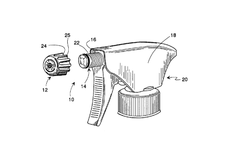
FIG. 1 is a perspective view of an adjustable nozzle
assembly constructed according to the teachings of the
present invention and shows a nozzle cap unthreadedly
detached from a nose bushing which is Mounted to the body
of a trigger sprayer.
FIG. 2 is a front view of the removed nozzle cap shown
in FIG. 1 and shows an alternating rib and groove pattern
on the exterior of the nozzle cap for facilitating
engagement of the nozzle cap.
FIG. 3 is a vertical sectional view, is taken along
line 3-3 Of FIG. 2 and shows a flange skirt of the nozzle
cap having a stepped inner surface forwardly of threads
inside the flange skirt.
FIG. 4 is a top view of the nose bushing and shows one
angular groove in the outer annular periphery of a face
disc of the bushing.
FIG. 5 is a horizontal sectional view of the nose
bushing, is taken along line 5-5 in FIG. 4 and shows an
axial central passageway in the bushing and two radial
passageways through the bushing through which liquid
passes.
FIG. 6 is a side elevational view of the nose bushing
and is taken along line 6-6 of FIG. 4.
FIG. 7 is a front elevational view of the integral
nose bushing, is taken along line 7-7 of FIG. 6 and shows
an angular groove in the outer annular periphery of the
nose bushing face disc.
FIG. 8 is a rear elevational view of the nose bushing
and is taken along line 8-8 of FIG. 6.
FIG. 9 is a front and side perspective view of the
nose bushing and shows the front seating surface of the
nose bushing face disc, an externally threaded portion
forward of a midbushing base, and rearwardly extending
mounting flanges.
~ 2~87~7 2~
6A
FIG. 10 is a sectional view of the nozzle cap fully
threaded onto the nose bushing and a fragmentary top plan
view of the front and of the nose bushing, is taken along
line 10-10 of FIG. 2, and shows the front seating surface
of the nose bushing face disc fully seated against an inner
wall surface in the nozzle cap to provide an off mode
position for the containment of a liquid.
~ /0723~ 1 cr~ 2-7
FIG. 11 is a sectional view, similar to FIG. lO, or th~
nozzle cap, but showing the nozzle cap partially unthreaded
from the nose bushing where the front seating surface or th~
nose bushing face disc is unseated from the inner wall surrace
5 of the nozzle cap with the outer annular periphery of the dicc
still sealingly engaging an annular wall surface of th~ stepped
surface of the flange skirt to define a swirl chamb~r be~ween
the inner wall surface and the face disc and whereby liquid is
channeled through the angular ~rooves in the ou~er annular
10 periphery of the face disc into the swirl chamber to provide a
spray mode position of the adjustable nozzle assembly ~Ihere
liquid is discharged in a generally conical spray pat~ern.
FIG. 12 is a sectional view, similar to FIG. lo, of the
nozzle cap, but showing the nozzle cap further unthread~d from
15 the nose bushing to space the inner wall surface of the cap
further from the face disc to form a larger chamber and to
disengage the outer annular periphery from the annular wall
surface of the stepped surface to allow liquid to flow over the
outer annular periphery of the face disc without any specified
20 direction into the larger c~am~er to provide a stream or jet
position wherein liquid is discharged in a stream or jet
pattern.
W~9l/07~3~ t~
8 ~068727
~_ DESCRIPTION OF ~ ~ PREFERRED E~DIMENl'
With reference to FIG. 1, the adjustable nozzl~ ass~m~ly
10 comprises two integral parts, namely a nozzle c~p 1~ and 1
nose bushing 14. The nose bushing 14 is ~dapted to be mounted
5 to the front end 16 of the body 18 of a tri~ger sprayer ~ O
which is mounted on a container of liquid.
As observed in U.S. Pat. No. 4,247,048, a noz~le cap and
a nose bushing preferahly are made o~ dissimilar th~rmo-
plastic materials such as polypropylene, polyethyl~n~,10 polyethylene terep~thalate, nylon, or ABs Plastic. In thi~
way, the cap and nose bushing are of dissimilar materials ~Jith
one material ~eing harder than the other to provid~ high
fidelity liquid seals as the harder material will ~'seat" into
the softer material.
The nozzle cap 12 and nose bushing 14 of the nozzle
assembly 10 are each integral pieces which may be fabricated of
different materials by conventional injection molding
techniques known to those skilled in the art.
Referring to the drawings in greater detail, there is
20 illustrated in FIG. 1, the nozzle cap 12 disengaged frcm an
externally threaded portion 22 of the nose bushing 1~ which is
mounted to the triqger sprayer 20.
As shown in FIGS. 1 and 2, the nozzle cap 1~ has
alternating, axially extending, grooves 2~ and ribs 25 which
25 facilitate finger and thumb engagement with the cap 12 ~or
rotating same. A front face 26 of the cap 12 has indicia ~'OPEN
TWIST~' plus an arrow thereon.
As shown in FIG. 3, the nozzle cap 12 includes a ~ront
wall 28 disposed between the front face 26 and an inner wall
30 surface 30 and a rearwardly extending sleeve or f~ange s~irt
32. The rear portion of the flange skirt 3~ has int~rnal
threads 34 adapted to engage the threaded portion 22 of the
nose bushing 14. Forwardly of the threads 34, inside the ~irt
flange 32 of the cap 12 is a stepped formation 3~ including a
35 first frusto-conical surface 38, a first annular surface ~0, a
second frusto-conical surface 42, and a second annular surface
44, extending to the inner wall surface 30 which is slightly
frusto-conical at 46 inwardly to a flat radially extending
surface 48.
2 Q ~
The front wall 28 has an outlet orifice 49 extending
therethrough in the center thereof between the inner wall
surface 30 and the front face 26.
FIGS. 4-9, are views of the nose bushing 14 and show
various portions thereof. The nose bushing 14 includes a face
disc 50 having a front face 52 which is slightly frusto-conical
at 54 and flat at 56 in the center thereof. The front face 52
is configured and sized to seat against the inner wall surface
30 of the nozzle cap (FIG. 3). The face disc 50 is separated
from the threaded portion 22 by an annular slot 58 and has an
outer annular periphery 60. The annular periphery 60 has two
angularly exte~;ng diametrically opposed grooves 61, 62 (FIG.
5) therein for directing liquid flowing therethrough in a swirl
pattern between the front face 52 and the inner wall surface
30. The grooves 61-62 are tangential to a cylindrical envelope
passing through the grooves 61, 62 and traverse or skew to the
elongate axis of the nose bushing 14.
The portions of the nose bushing 14 are integral and at
the rear end of the threaded portion 22 is a mid-bushing base
64 which is received against the front end 16 of the body 18
of the trigger.
Extending rearwardly from the base 64 is a tubular body
portion 68 having an axial passageway 70 (Fig. 5) extending
through to base 64 and the threaded portion 22 to the back of
the nose disc 50 where two radial passageways 71, and 72 extend
radially outwardly to the annular slot 58 and through a back
side 73 of the nose disc 50 to the slots 61 and 62 as shown in
FIG. 5.
The tubular body portion 68 of the nose bushing 14 is
coupled to a liquid supply tube or conduit in a conventional
manner.
In the embodiment illustrated in FIGS. 4 through 9, the
nose bushing includes spaced apart; axially extending flanges
81 and 82 which extend rearwardly from rear wall face 84 of the
mid-bushing base 64. Extending perpendicularly inwardly from
the rearwardly extending flanges 81 and 82 are two pairs of
mounting shelves 91, 92.
The face disc 50 has rounded annular corners at the front
and rear edges of its annular periphery 60 to facilitate
movement of the nozzle cap 12 on the outer annular periphery
2 ~ ~ 8 7 ~ 7
'Ib~ ~.
60.
In FIGS. 10 through 12 there is illustrated,
respectively, the off made, spray mods, and stream mode
positions of the adjustable nozzle assembly 10. In all
such modes, a rubber 0-ring 94 is located in the annular
slot 58 between the face disc 50 and the threaded portion
22 and sealingly engages the first annular surface 40.
More particularly, in FIG. 10 there is shown the off
mode position of the adjustable nozzle assembly 10. In
this mode, the nozzle cap 12 is screwed upon the externally
threaded portion 22 of the nose bushing 14. In this off
mode, the outer periphery 60 of the nose bushing face disc
50 is in flush contact with the second annular surface 44
in the nozzle cap flange skirt 32. Also, the front face 52
is in flush sealing contact with the inner wall surface 30
of the nozzle cap 12.
The spray mode position of the adjustable nozzle,
assembly 10 is illustrated in FIG. 11. In FIG. 11, the
rotatable nozzle cap 12 has been rotated outwardly off the
threaded portion 22 of the nose bushing 14 a sufficient
distance to a second position where the inner wall surface
30 of the nozzle cap 12 is moved forward from the front
seating surface 52 of the nose bushing face disc 50 to an
unseated position. This unseated Position defines a swirl
chamber 100 between the front seating surface 52 of the
nozzle bushing face disc 50 and the inner wall surface 30
of the nozzle cap 12 and permits liquid from the axial
passageway 70 (FIG. 5) and the radial passageways 71 and 72
(FIG. 5) to flow to and through the angular spin causing
grooves 61 and 62 (FIG. 7) into the swirl chamber 100 in a
circular or spinning motion for discharge through the
discharge orifice 49 in the front wall 28 of the nozzle cap
12 in a conical spray pattern. The swirl chamber 100 is
defined between the second annular surface 44, the front
seating surface 52 of the face disc 50 and the inner wall
surface 30 of the nozzle cap 12.
.,
.
. ,
7z~
....
lOA
In this respect, note that the outer periphery 60 of
the face disc 50 is still in sealing engagement with the
annular surface 44 whereby liquid flow is constrained to
flow, or is channeled through the angular groves 61 and 62
(FIG. 7) to create a swirl flow in the swirl chamber 100.
The conical
spray mode of operation of the adjustable nozzle assembly
10 is characterized by the unseating of the front seating
surface 52 from the inner wall surface 30, but with the
annular periphery, 60 of the nose bushing face disc 50
remaining in flush contact with the annular surface 44 in
the nozzle cap flange skirt 32, so as to not permit liquid
to move over or around the nose bushing face disc 50 into
the swirl chamber 100 but only to permit liquid to flow
through the angular spin-causing grooves 61, 62 into the
swirl chamber 100 in a circular or spinning motion for
discharge out of the nozzle cap discharge orifice 49 in a
conical spray pattern.
In FIG. 12 there is illustrated a stream or jet mode
position of the adjustable nozzle assembly 10 where the
nozzle cap 12 is unthreaded further outwardly from the nose
bushing 14 to create a larger chamber 102, the annular
periphery 60 of the nose bushing face disc 50 is located
opposite and spaced from the larger diameter annular
surface 40 in the nozzle cap flange skirt 32. The
discharge of liquid in this mode will be changed to a
stream or jet pattern due to the fact that liquid from the
radial passageways 71 and 72 (FIG. 5) can now pass over and
around the annular periphery 60 of the nose bushing face
disc 50 and is not constrained to flow through the angular
spin-causing grooves 61, 62 for entry into the larger
chamber 102 for discharge out of the nozzle cap discharge
orifice 49. As a result, the liquid flow is not directed
or channeled and the non-specific liquid flow is basically
radially inwardly to the discharge orifice 49 and not in a
swirl. This results in a stream discharged from the outlet
orifice 49.
It is believed that the adjustable nozzle assembly 10
of the present invention and its numerous attendant
advantages will be fully understood from the foregoing
description, and that changes may be made in form,
7 ~ 7
' ,~ , ~,..
llA
construction, and arrangement of the several parts thereof
without departing from the scope of the invention, or
sacrificing any of the attended advantages. The structures
herein disclosed are preferred embodiments for the purpose
of illustrating the invention. Accordingly, the scope of
the invention is only to be limited as necessitated by the
accompanying claims.