Language selection

Search

Patent 2068736 Summary

Third-party information liability

Some of the information on this Web page has been provided by external sources. The Government of Canada is not responsible for the accuracy, reliability or currency of the information supplied by external sources. Users wishing to rely upon this information should consult directly with the source of the information. Content provided by external sources is not subject to official languages, privacy and accessibility requirements.

Claims and Abstract availability

Any discrepancies in the text and image of the Claims and Abstract are due to differing posting times. Text of the Claims and Abstract are posted:

  • At the time the application is open to public inspection;
  • At the time of issue of the patent (grant).
(12) Patent Application: (11) CA 2068736
(54) English Title: CIRCULAR SAW BLADE ASSEMBLY
(54) French Title: ASSEMBLAGE DE LAMES DE SCIE CIRCULAIRE
Status: Deemed Abandoned and Beyond the Period of Reinstatement - Pending Response to Notice of Disregarded Communication
Bibliographic Data
(51) International Patent Classification (IPC):
  • B27B 33/20 (2006.01)
  • B23D 61/02 (2006.01)
  • B27B 5/34 (2006.01)
(72) Inventors :
  • RAUTIO, KAUKO (Finland)
(73) Owners :
  • KAUKO RAUTIO
(71) Applicants :
(74) Agent: MARKS & CLERK
(74) Associate agent:
(45) Issued:
(86) PCT Filing Date: 1990-12-05
(87) Open to Public Inspection: 1991-06-21
Availability of licence: N/A
Dedicated to the Public: N/A
(25) Language of filing: English

Patent Cooperation Treaty (PCT): Yes
(86) PCT Filing Number: PCT/FI1990/000291
(87) International Publication Number: WO 1991008875
(85) National Entry: 1992-05-14

(30) Application Priority Data:
Application No. Country/Territory Date
896146 (Finland) 1989-12-20

Abstracts

English Abstract


ABSTRACT OF THE DISCLOSURE
The present invention concerns a circular saw blade
assembly for a saw mill or similar apparatus used for-sawing
boards from logs, said circular saw blade assembly comprising
at least two circular saw blades (2) attachable to and
axially transferrable on a saw blade spindle (1) as well as
one or several edge milling cutters for shaping the board to
a correct width. The circular saw blade assembly in
accordance with the invention is implemented so that the
edging cutter is formed by edge cutter elements (3, 4)
adapted to adjacent circular saw blades (2, 5), whereby the
cutter elements are axially adjustable in relation to each
other along with the spacing adjustment of the circular saw
blades (2, 5), and each cutter element (3, 4) is comprised of
one or several cutter knives (6) and a block section (7)
having a recess machined to its face opposing the adjacent
cutter element and having a penetrating hole for the saw
spindle (1) to pass, whereby the knives (6) of the adjacent
cutter elements (3, 4) are aligned to rotate along a single
circle with an axial displacement of the elements at the
different points along the cutting circle.


Claims

Note: Claims are shown in the official language in which they were submitted.

WO 91/08875 PCT/F190/00291
THE EMBODIMENTS OF THE INVENTION IN WHICH AN EXCLUSIVE
PROPERTY OR PRIVILEGE IS CLAIMED ARE DEFINED AS FOLLOWS:
1. A circular saw blade assembly for a saw mill or simi-
lar apparatus used for sawing boards from logs, said cir-
cular saw blade assembly comprising at least two circular
saw blades (2) attachable to and axially transferrable on
a saw blade spindle (l) as well as one or several edging
cutters for shaping the board to a correct width,
c h a r a c t e r i z e d in that the edging cutter is
formed by edge cutter elements (3, 4) adapted to adjacent
circular saw blades (2, 5) so that the elements are
axially adjustable in relation to each other along with
the spacing adjustment of the circular saw blades (2, 5)
and the cutter elements (3, 4) are comprised of one or
several cutter knives (6) and a block section (7) having
a recess machined to its face opposing the adjacent
cutter element and having a penetrating hole for the saw
spindle (l) to pass, whereby the knives (6) of the ad-
jacent cutter elements (3, 4) are aligned to rotate along
a single circle with an axial displacement of the ele-
ments at the different points along the cutting circle.
2. An assembly as claimed in claim l, c h a r a c -
t e r i z e d in that the both cutter elements (3, 4)
are comprised of two diametrically oppositely placed
cutter knives (6) and that the adjacent cutter elements
(3, 4) are phase-shifted by 90° angle.
3. An apparatus as claimed in claim l, c h a r a c -
t e r i z e d in that both cutter elements (3, 4) are
comprised of three cutter knives (6) diametrically spaced
at l20° angle and that the adjacent cutter elements
(3, 4) are phase-shifted by 60° angle.

WO91/08875 PCT/FI90/00291
4. An apparatus as claimed in any of claims 1...3,
c h a r a c t e r i z e d in that the cutter element
(3) is attached to the circular saw blade by screw clamps
and that the surface of the cutter element (3) facing
circular saw blade (1) is flat.

Description

Note: Descriptions are shown in the official language in which they were submitted.


3 ~
WO91/08~75 PCT/Fl90/00291
CIRCULAR SAW BLADE ASSEMBLY
The present invention concerns a circular saw blade
assembly for a saw mill or similar apparatus used for
sawing boards from logs, said circular saw blade assembly
comprising at least two circular saw blades attachable to
and axially transferrable on a saw blade spindle as well
as one or several edge milling cutters for shaping the
board to a correct width.
Known in the art is a method for placing several circular
saw blades axially transferrably on a common shaft
(US 3,630,244). This arrangement has a drawback in that
the gap between the adjacent circular saw blades does
permit the placement of edge shaping cutters to correct
width for the trimming of the boards, but instead, the
milling of the edge must be performed as a separate
workphase.
Also known in the art is an arrangement in which the
edging of the log prior sawing is unnecessary and which
makes the axial adjustment of spacing between the saw
blades possible. One such implementation is disclosed in
FI patent application 881402. The system described in the
application comprises a circular saw blade assembly which
has two circular saw blades on a spindle and the spindle
hubs are further designed to act as cutters, whereby the
cutter attached to the inner circular saw blade is formed
into a cage supporting by its end side an inner circu~ar
saw blade, and the inner cutter supporting an outer
circular saw blade by its end side is located axially
transferrable inside the cage-like cutter and extends
through the center hole of the inner circular saw blade.

3 ~ 3 ~
WO91/0~875 P~T/~1~0/002~1
Such an axlally adjustable circ-ular saw blade assembly
has only two circular saw blades, whereby only a wane and
a slab can be cut from a log. The construction of the
circular saw blade assembly i9 complicated, thereby
leading to high costs. One of the cutters has constantly
a maximum width, which causes wasteful use of log
material, and correspondingly, to unnecessary growth of
expenses. In addition, the diametrical difference of the
cutters is small, which limits their useful operating
range.
It is an object of the present invention to achieve a
circular saw blade aQsembly capable of overcoming the
above-described drawbacks. The assembly in accordance
with the invention is characterized in that the edging
cutters are formed by cutter elements adapted to adjacent
circular saw blades so that the elements are axially
adjustable in relation to each other and the cutter
elements are comprised of one or several cutter knives
and a block section having a recess machined into the
face opposing the adjacent cutter element and having a
penetrating hole for the saw spindle to pass, whereby the
knives of the adjacent cutter elements are aligned rotate
along a single circle with an axial.displacement of the
elements at the different points along the cutting
circle.
A preferred embodiment of the assembly in accordance with
the invention is characterized in that both cutter
elements are comprised of two diametrically oppositely
placed cutter knives and that the adjacent cutter
elements are phase-shifted by a 90 angle.

2~7~
WO91/0887~ P~T/F190/00291
Another preferred embodiment of the method in accordance
with the invention is characterized in that both cutter
elements are comprised of three cutter knives diametri-
cally spaced at 120 angle and that the adjacent~cutter
elements are phase-shifted by 60 angle.
A further another preferred embodiment of the method in
accordance with the invention is characterized in that
the cutter elements are attached to the circular saw
blade by screw clamps and that the surface of the cutter
element facing circular saw blade is flat.
The circular saw blade assembly in accordance with the
invention offers an improved support of the blade between
the flanges. All circular saw bladeQ of the assembly are
axially movable, whereby the edge cutter element~ are
simultaneously adjusted correspondingly, thu~ making it
easy to alter the thickness of the board to be sawn
without a need for changing the edge cutter elements. The
construction of the as~embly is simple and the edge
cutter elements are replaceable, whereby the operation
and maintenance of the assembly becomes advantageous. The
diameter of an edge cutter element is not dependent on
that of the other edge cutter elements, thus allowing for
a free alteration of the element diameters. The number of
the circular saw blades in the circular saw blade
assembly in accordance with the invention is not limited,
but instead, the same saw spindle can have several
circular saw blades and independently operating edge
cutter elements placed on it.
In the following, the invention will be examined in
more detail with the help of a preferred exemplifying

~'3 '3~
WO91/08875 PCT/F190/OOZ91
embodlment with reference to the attached drawings, in
which
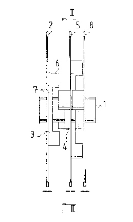
Fig. l shows in a side view a circular saw blade
assembly in accordance with the invention.
Fig. 2 shows the assembly illustrated in Fig. l
sectioned along line II-II.
Fig. l shows a circular saw blade assembly comprising
three circular saw blades 2, 5, 8 mounted on a saw
spindle l. Attached to the circular saw blades 2, 5, 8
are edge cutter elements 3. The pair of adjacent cutter
elements 3, 4 forms an edge cutter. The edge cutter is
axially adjustable along with the variable spacing of the
circular saw blade 2, 5. An essential characteristic of
the invention is that the cutter knives 6 of the edge
cutter elements 3, 4 rotate axially coincidingly aligned
along the same circle when the edge cutter is adjusted
for minimum width, while the side edge of the cutter
knife 6 of the cutter element 3 facing the cutter element
4 rotates axially coincidingly aligned with the side edge
of the cutter knife 6 of the cutte.r element 4 facing the
cutter element 3 when the edge cutter is adjusted for
maximum width. Thus, for instance, when thicker boards
are to be sawn, the circular saw blade 5 is moved farther
away from the circular saw blade 2. Then, the edge cut-
ter element 4 moves along with the circular saw blade 5,
whereby the cutting width of the edge cutter is altered
correspondingly. The cutter illustrated in the diagram
between the circular saw blades 2 and 5 is shown adjusted
to a nearly maximum width. Conversely, the cutter between

r~
WO 91/08~75 PCr/FI90/00291
-he circular saw blades S and 8 is shown adjusted to a
nearly minimum width.
Fig. 2 shows the circular saw blade 2, the edge c-utter
element 3 and the edge cutter element 4 attached to the
adjacent circular saw blade in partially sectional view.
The cutter knives 6 of the edge cutter elements 3, 4 are
diametrically opposed on the same circle and the two
cutter elements are phase-shifted by 90.
For those versed in the art, it is obvious that the
invention is not limited to the exemplifying embodiments
described above; by contrast, the invention can be varied
within the claims disclo~ed herein.

Representative Drawing
A single figure which represents the drawing illustrating the invention.
Administrative Status

2024-08-01:As part of the Next Generation Patents (NGP) transition, the Canadian Patents Database (CPD) now contains a more detailed Event History, which replicates the Event Log of our new back-office solution.

Please note that "Inactive:" events refers to events no longer in use in our new back-office solution.

For a clearer understanding of the status of the application/patent presented on this page, the site Disclaimer , as well as the definitions for Patent , Event History , Maintenance Fee  and Payment History  should be consulted.

Event History

Description Date
Time Limit for Reversal Expired 1996-06-05
Application Not Reinstated by Deadline 1996-06-05
Deemed Abandoned - Failure to Respond to Maintenance Fee Notice 1995-12-05
Inactive: Adhoc Request Documented 1995-12-05
Application Published (Open to Public Inspection) 1991-06-21

Abandonment History

Abandonment Date Reason Reinstatement Date
1995-12-05
Owners on Record

Note: Records showing the ownership history in alphabetical order.

Current Owners on Record
KAUKO RAUTIO
Past Owners on Record
None
Past Owners that do not appear in the "Owners on Record" listing will appear in other documentation within the application.
Documents

To view selected files, please enter reCAPTCHA code :


To view images, click a link in the Document Description column. To download the documents, select one or more checkboxes in the first column and then click the "Download Selected in PDF format (Zip Archive)" or the "Download Selected as Single PDF" button.

List of published and non-published patent-specific documents on the CPD .

If you have any difficulty accessing content, you can call the Client Service Centre at 1-866-997-1936 or send them an e-mail at CIPO Client Service Centre.


Document
Description 
Date
(yyyy-mm-dd) 
Number of pages   Size of Image (KB) 
Cover Page 1991-06-21 1 11
Claims 1991-06-21 2 40
Abstract 1991-06-21 1 26
Drawings 1991-06-21 1 15
Descriptions 1991-06-21 5 141
Representative drawing 1999-09-30 1 6
Fees 1994-11-14 1 55
Fees 1993-11-19 1 37
Fees 1992-10-28 1 28
International preliminary examination report 1992-05-14 18 306