Sélection de la langue

Search

Sommaire du brevet 2068736 

Énoncé de désistement de responsabilité concernant l'information provenant de tiers

Une partie des informations de ce site Web a été fournie par des sources externes. Le gouvernement du Canada n'assume aucune responsabilité concernant la précision, l'actualité ou la fiabilité des informations fournies par les sources externes. Les utilisateurs qui désirent employer cette information devraient consulter directement la source des informations. Le contenu fourni par les sources externes n'est pas assujetti aux exigences sur les langues officielles, la protection des renseignements personnels et l'accessibilité.

Disponibilité de l'Abrégé et des Revendications

L'apparition de différences dans le texte et l'image des Revendications et de l'Abrégé dépend du moment auquel le document est publié. Les textes des Revendications et de l'Abrégé sont affichés :

  • lorsque la demande peut être examinée par le public;
  • lorsque le brevet est émis (délivrance).
(12) Demande de brevet: (11) CA 2068736
(54) Titre français: ASSEMBLAGE DE LAMES DE SCIE CIRCULAIRE
(54) Titre anglais: CIRCULAR SAW BLADE ASSEMBLY
Statut: Réputée abandonnée et au-delà du délai pour le rétablissement - en attente de la réponse à l’avis de communication rejetée
Données bibliographiques
Abrégés

Abrégé anglais


ABSTRACT OF THE DISCLOSURE
The present invention concerns a circular saw blade
assembly for a saw mill or similar apparatus used for-sawing
boards from logs, said circular saw blade assembly comprising
at least two circular saw blades (2) attachable to and
axially transferrable on a saw blade spindle (1) as well as
one or several edge milling cutters for shaping the board to
a correct width. The circular saw blade assembly in
accordance with the invention is implemented so that the
edging cutter is formed by edge cutter elements (3, 4)
adapted to adjacent circular saw blades (2, 5), whereby the
cutter elements are axially adjustable in relation to each
other along with the spacing adjustment of the circular saw
blades (2, 5), and each cutter element (3, 4) is comprised of
one or several cutter knives (6) and a block section (7)
having a recess machined to its face opposing the adjacent
cutter element and having a penetrating hole for the saw
spindle (1) to pass, whereby the knives (6) of the adjacent
cutter elements (3, 4) are aligned to rotate along a single
circle with an axial displacement of the elements at the
different points along the cutting circle.

Revendications

Note : Les revendications sont présentées dans la langue officielle dans laquelle elles ont été soumises.


WO 91/08875 PCT/F190/00291
THE EMBODIMENTS OF THE INVENTION IN WHICH AN EXCLUSIVE
PROPERTY OR PRIVILEGE IS CLAIMED ARE DEFINED AS FOLLOWS:
1. A circular saw blade assembly for a saw mill or simi-
lar apparatus used for sawing boards from logs, said cir-
cular saw blade assembly comprising at least two circular
saw blades (2) attachable to and axially transferrable on
a saw blade spindle (l) as well as one or several edging
cutters for shaping the board to a correct width,
c h a r a c t e r i z e d in that the edging cutter is
formed by edge cutter elements (3, 4) adapted to adjacent
circular saw blades (2, 5) so that the elements are
axially adjustable in relation to each other along with
the spacing adjustment of the circular saw blades (2, 5)
and the cutter elements (3, 4) are comprised of one or
several cutter knives (6) and a block section (7) having
a recess machined to its face opposing the adjacent
cutter element and having a penetrating hole for the saw
spindle (l) to pass, whereby the knives (6) of the ad-
jacent cutter elements (3, 4) are aligned to rotate along
a single circle with an axial displacement of the ele-
ments at the different points along the cutting circle.
2. An assembly as claimed in claim l, c h a r a c -
t e r i z e d in that the both cutter elements (3, 4)
are comprised of two diametrically oppositely placed
cutter knives (6) and that the adjacent cutter elements
(3, 4) are phase-shifted by 90° angle.
3. An apparatus as claimed in claim l, c h a r a c -
t e r i z e d in that both cutter elements (3, 4) are
comprised of three cutter knives (6) diametrically spaced
at l20° angle and that the adjacent cutter elements
(3, 4) are phase-shifted by 60° angle.

WO91/08875 PCT/FI90/00291
4. An apparatus as claimed in any of claims 1...3,
c h a r a c t e r i z e d in that the cutter element
(3) is attached to the circular saw blade by screw clamps
and that the surface of the cutter element (3) facing
circular saw blade (1) is flat.

Description

Note : Les descriptions sont présentées dans la langue officielle dans laquelle elles ont été soumises.

3 ~
WO91/08~75 PCT/Fl90/00291
CIRCULAR SAW BLADE ASSEMBLY
The present invention concerns a circular saw blade
assembly for a saw mill or similar apparatus used for
sawing boards from logs, said circular saw blade assembly
comprising at least two circular saw blades attachable to
and axially transferrable on a saw blade spindle as well
as one or several edge milling cutters for shaping the
board to a correct width.
Known in the art is a method for placing several circular
saw blades axially transferrably on a common shaft
(US 3,630,244). This arrangement has a drawback in that
the gap between the adjacent circular saw blades does
permit the placement of edge shaping cutters to correct
width for the trimming of the boards, but instead, the
milling of the edge must be performed as a separate
workphase.
Also known in the art is an arrangement in which the
edging of the log prior sawing is unnecessary and which
makes the axial adjustment of spacing between the saw
blades possible. One such implementation is disclosed in
FI patent application 881402. The system described in the
application comprises a circular saw blade assembly which
has two circular saw blades on a spindle and the spindle
hubs are further designed to act as cutters, whereby the
cutter attached to the inner circular saw blade is formed
into a cage supporting by its end side an inner circu~ar
saw blade, and the inner cutter supporting an outer
circular saw blade by its end side is located axially
transferrable inside the cage-like cutter and extends
through the center hole of the inner circular saw blade.

3 ~ 3 ~
WO91/0~875 P~T/~1~0/002~1
Such an axlally adjustable circ-ular saw blade assembly
has only two circular saw blades, whereby only a wane and
a slab can be cut from a log. The construction of the
circular saw blade assembly i9 complicated, thereby
leading to high costs. One of the cutters has constantly
a maximum width, which causes wasteful use of log
material, and correspondingly, to unnecessary growth of
expenses. In addition, the diametrical difference of the
cutters is small, which limits their useful operating
range.
It is an object of the present invention to achieve a
circular saw blade aQsembly capable of overcoming the
above-described drawbacks. The assembly in accordance
with the invention is characterized in that the edging
cutters are formed by cutter elements adapted to adjacent
circular saw blades so that the elements are axially
adjustable in relation to each other and the cutter
elements are comprised of one or several cutter knives
and a block section having a recess machined into the
face opposing the adjacent cutter element and having a
penetrating hole for the saw spindle to pass, whereby the
knives of the adjacent cutter elements are aligned rotate
along a single circle with an axial.displacement of the
elements at the different points along the cutting
circle.
A preferred embodiment of the assembly in accordance with
the invention is characterized in that both cutter
elements are comprised of two diametrically oppositely
placed cutter knives and that the adjacent cutter
elements are phase-shifted by a 90 angle.

2~7~
WO91/0887~ P~T/F190/00291
Another preferred embodiment of the method in accordance
with the invention is characterized in that both cutter
elements are comprised of three cutter knives diametri-
cally spaced at 120 angle and that the adjacent~cutter
elements are phase-shifted by 60 angle.
A further another preferred embodiment of the method in
accordance with the invention is characterized in that
the cutter elements are attached to the circular saw
blade by screw clamps and that the surface of the cutter
element facing circular saw blade is flat.
The circular saw blade assembly in accordance with the
invention offers an improved support of the blade between
the flanges. All circular saw bladeQ of the assembly are
axially movable, whereby the edge cutter element~ are
simultaneously adjusted correspondingly, thu~ making it
easy to alter the thickness of the board to be sawn
without a need for changing the edge cutter elements. The
construction of the as~embly is simple and the edge
cutter elements are replaceable, whereby the operation
and maintenance of the assembly becomes advantageous. The
diameter of an edge cutter element is not dependent on
that of the other edge cutter elements, thus allowing for
a free alteration of the element diameters. The number of
the circular saw blades in the circular saw blade
assembly in accordance with the invention is not limited,
but instead, the same saw spindle can have several
circular saw blades and independently operating edge
cutter elements placed on it.
In the following, the invention will be examined in
more detail with the help of a preferred exemplifying

~'3 '3~
WO91/08875 PCT/F190/OOZ91
embodlment with reference to the attached drawings, in
which
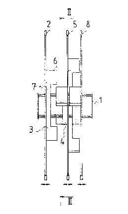
Fig. l shows in a side view a circular saw blade
assembly in accordance with the invention.
Fig. 2 shows the assembly illustrated in Fig. l
sectioned along line II-II.
Fig. l shows a circular saw blade assembly comprising
three circular saw blades 2, 5, 8 mounted on a saw
spindle l. Attached to the circular saw blades 2, 5, 8
are edge cutter elements 3. The pair of adjacent cutter
elements 3, 4 forms an edge cutter. The edge cutter is
axially adjustable along with the variable spacing of the
circular saw blade 2, 5. An essential characteristic of
the invention is that the cutter knives 6 of the edge
cutter elements 3, 4 rotate axially coincidingly aligned
along the same circle when the edge cutter is adjusted
for minimum width, while the side edge of the cutter
knife 6 of the cutter element 3 facing the cutter element
4 rotates axially coincidingly aligned with the side edge
of the cutter knife 6 of the cutte.r element 4 facing the
cutter element 3 when the edge cutter is adjusted for
maximum width. Thus, for instance, when thicker boards
are to be sawn, the circular saw blade 5 is moved farther
away from the circular saw blade 2. Then, the edge cut-
ter element 4 moves along with the circular saw blade 5,
whereby the cutting width of the edge cutter is altered
correspondingly. The cutter illustrated in the diagram
between the circular saw blades 2 and 5 is shown adjusted
to a nearly maximum width. Conversely, the cutter between

r~
WO 91/08~75 PCr/FI90/00291
-he circular saw blades S and 8 is shown adjusted to a
nearly minimum width.
Fig. 2 shows the circular saw blade 2, the edge c-utter
element 3 and the edge cutter element 4 attached to the
adjacent circular saw blade in partially sectional view.
The cutter knives 6 of the edge cutter elements 3, 4 are
diametrically opposed on the same circle and the two
cutter elements are phase-shifted by 90.
For those versed in the art, it is obvious that the
invention is not limited to the exemplifying embodiments
described above; by contrast, the invention can be varied
within the claims disclo~ed herein.

Dessin représentatif
Une figure unique qui représente un dessin illustrant l'invention.
États administratifs

2024-08-01 : Dans le cadre de la transition vers les Brevets de nouvelle génération (BNG), la base de données sur les brevets canadiens (BDBC) contient désormais un Historique d'événement plus détaillé, qui reproduit le Journal des événements de notre nouvelle solution interne.

Veuillez noter que les événements débutant par « Inactive : » se réfèrent à des événements qui ne sont plus utilisés dans notre nouvelle solution interne.

Pour une meilleure compréhension de l'état de la demande ou brevet qui figure sur cette page, la rubrique Mise en garde , et les descriptions de Brevet , Historique d'événement , Taxes périodiques et Historique des paiements devraient être consultées.

Historique d'événement

Description Date
Le délai pour l'annulation est expiré 1996-06-05
Demande non rétablie avant l'échéance 1996-06-05
Réputée abandonnée - omission de répondre à un avis sur les taxes pour le maintien en état 1995-12-05
Inactive : Demande ad hoc documentée 1995-12-05
Demande publiée (accessible au public) 1991-06-21

Historique d'abandonnement

Date d'abandonnement Raison Date de rétablissement
1995-12-05
Titulaires au dossier

Les titulaires actuels et antérieures au dossier sont affichés en ordre alphabétique.

Titulaires actuels au dossier
KAUKO RAUTIO
Titulaires antérieures au dossier
S.O.
Les propriétaires antérieurs qui ne figurent pas dans la liste des « Propriétaires au dossier » apparaîtront dans d'autres documents au dossier.
Documents

Pour visionner les fichiers sélectionnés, entrer le code reCAPTCHA :


Pour visualiser une image, cliquer sur un lien dans la colonne description du document. Pour télécharger l'image (les images), cliquer l'une ou plusieurs cases à cocher dans la première colonne et ensuite cliquer sur le bouton "Télécharger sélection en format PDF (archive Zip)" ou le bouton "Télécharger sélection (en un fichier PDF fusionné)".

Liste des documents de brevet publiés et non publiés sur la BDBC .

Si vous avez des difficultés à accéder au contenu, veuillez communiquer avec le Centre de services à la clientèle au 1-866-997-1936, ou envoyer un courriel au Centre de service à la clientèle de l'OPIC.


Description du
Document 
Date
(aaaa-mm-jj) 
Nombre de pages   Taille de l'image (Ko) 
Revendications 1991-06-20 2 40
Abrégé 1991-06-20 1 26
Dessins 1991-06-20 1 15
Description 1991-06-20 5 141
Dessin représentatif 1999-09-29 1 6
Taxes 1994-11-13 1 55
Taxes 1993-11-18 1 37
Taxes 1992-10-27 1 28
Rapport d'examen préliminaire international 1992-05-13 18 306