Note: Descriptions are shown in the official language in which they were submitted.
TITLE OF THE INVENTION
COLOR CATHODE RAY TUBE HAVING AN INTERMEDIATE LAYER
BETWEEN A FACE PLATE AND A TRICOLOR PHOSPHOR LAYER
BACKGROUND OF THE INVENTION
1. Field of the Invention
The present invention relates to a color cathode ray
tube having a selective light absorption layer which not
only includes a selective light absorption layer or a
neutral filter layer formed over the inner surface of the
face plate, but also a functional film such as an antistatic
film and a low reflection film formed over the outer surface
of the face plate.
2. Description of the Related Art
With the recent increase in the size of a color cathode
ray tube and the improvement in the brightness and the focus
control, a voltage to be applied to a phosphor screen of the
cathode ray tube, namely, the acceleration voltage of an
electron beam has been increased. For example, a voltage as
high as 30 to 34 kV is applied to the phosphor screen of a
recent color cathode ray tube having a size of not less than
30 inches.
As a result, the outer surface of the face plate of the
color cathode ray tube is apt to be charged up particularly
when the power of a television set is turned ON or OFF.
Since the charged-up outer surface of the face plate
" -
7 9 ~
attracts small dust particles floating in the air and is
tainted thereby, the brightness of the cathode ray tube is
impaired. In addition, when a viewer approaches the outer
surface of the charged-up face plate, an electric discharge
occurs, which disadvantageously brings discomfort to the
viewer.
Antistatic type color cathode ray tubes having a
functional film have come into general use in order to
prevent such a build up of charge on the outer surface of
the face plate. In these cathode ray tubes, a smooth
transparent conductive film is formed over the outer surface
of the face plate so as to release the charges on the face
plate to ground.
Fig. 13 is an explanatory view of the principle of the
antistatic effect of the above-described color cathode ray
tube having an antistatic type functional film. In Fig. 13,
the reference numeral 6 represents a neck portion which has
an electron gun (not shown) therein, 7 a deflection yoke, 4a
a funnel portion, 4 a face plate, and 5 a high voltage
button. The deflection yoke 7 is connected to the power
supply for deflection through a lead wire 7a, the electron
gun is connected to the power supply for acceleration
through a lead wire 6a and the high voltage button 5 is
connected to a high voltage power supply through a lead wire
5a. The electron gun provided in the neck portion 6 emits
electron beams toward the face plate 4. The deflection
- 2 -
7 ~ ~
yoke 7 electromagnetically reflects these electron beams
from the outside of the cathode ray tube, the high voltage
power supply applies a high voltage to the phosphor screen
provided on the inner surface of the face plate 4 through
the high voltage button 5. The applied high voltage accel-
erates the electron beams, and when the phosphor screen of
the face plate is bombarded with the electron beams, the
phosphor screen is excited by the energy produced by the
bombardment and emits light. In this way, an optical output
is taken out of the phosphor screen. By the influence of
the high voltage applied to the phosphor screen provided on
the inner surface of the face plate 4, the electric poten-
tial on the outer surface of the face plate 4 changes, as
described above, thereby causing a problem such as the
adhesion of dust particles.
In order to prevent such a problem, in the color
cathode ray tube having an antistatic type functional film
shown in Fig. 13, a smooth transparent conductive film,
namely, an antistatic type functional film 1 is formed over
the outer surface of the face plate 4, and the antistatic
type functional film is connected to a grounding wire 10
through a conductive tape 11, with an implosion preventive
metal band 8 and ears 9 welded thereto. In this way, the
charges generated on the face plate 4 are constantly
released to ground lOA, thereby preventing charge-up.
7 ~ ~
Since the smooth transparent conductive film 1, namely,
the antistatic type functional film formed over the outer
surface of the face plate 4 is required to have a certain
degree of mechanical strength, that is, a certain degree of
hardness and adhesiveness, a silica (SiO2) film is generally
used as the functional film 1.
In one of the conventional methods of forming the
smooth transparent conductive silica film, namely, antistat-
ic type silica functional film, an alcohol solution of
silicon (Si) alkkoxide including a functional group such as
an -OH group and an -OR group is uniformly and smoothly
applied onto the outer surface of the face plate of the
color cathode ray tube by spin coating or the like.
Thereafter the coating film is sintered at a relatively low
temperature, for example, at a temperature not higher than
100~C.
Fig. 14 is a schematic enlarged sectional view of an
antistatic type functional film 13 produced by forming a
porous silica (SiO2) film 12 on the outer surface of the
face plate 4 by the above-described method. On the inner
surface of the face plate 4 is formed a conventional phos-
phor screen composed of a black light absorbing layer 14,a
BGR phosphor layer 15 and a metal-backed layer 16.
Since the smooth transparent conductive silica (SiO2)
film 12 formed by the above-described method is porous and
2068792
incl~des a silanol sroup ( - Si-OH), it is possible to
reduce the surface resistivity of the face plate 4 by
absorbing the water content in the air. However, if the
porous silica (SiO2) film 12 is used in a dry environment
for a long time, the water content retained in the porous
film is evaporated and the surface resistivity increases
with time.
To solve this problem thoroughly, the following method
is adopted. Fine particles of tin oxide (SnO2), indium
oxide (ln2o3) or the like are dispersed in and mixed with an
alcohol solution of silicon (Si) alkoxide as a conductive
filler. A trace amount of phosphorus (P) or antimony (Sb)
is further added to the solution in order to impart a
semiconducting property thereto. The coating liquid ob-
tained in this way is uniformly and smoothly applied to the
outer surface of the face plate by spin coating or the like,
and the face plate coated with the coating liquid is
sintered at a comparatively high temperature (e.g., 100~C to
200~C).
Fig. 15 is a schematic enlarged sectional view of a
phosphor screen for explaining an antistatic type functional
film 17 formed in the above-described manner. Since conduc-
tive filler particles 18 exist in the porous silica (SiO2)
film 12 formed over the outer surface of the face plate 4,
i_ 's possihle .o produce the stable antistatic type
~ n ~
., ,,.,~
functional film 17 the surface resistivity of which does not
change with time in any environment.
With the recent strong demand for a high picture
quality with a color TV, a method including both the
above-described antistatic treatment and the improvement in
the contrast and the color tone of the light emitted from a
color cathode ray tube by coloring the transparent
conductive film formed over the face plate or controlling
the transmittance of the functional film 17 has begun to be
put into practical use.
That is, a selective light absorbing coating liquid or
a uniform light absorbing coating liquid is produced by
mixing the particles of an inorganic or organic pigment or
dye with a coating liquid for forming the conventional
antistatic type functional film 13 as a base so as to color
the coating liquid. The thus-obtained coating liquid is
applied to the outer surface of the face plate 4 of a color
cathode ray tube by spin coating. In this way, a color
cathode ray tube is completed which is provided with an
antistatic type selective light absorption film or an
antistatic type uniform light absorption film which has not
only an antistatic function, but which also has a filter
function for selectively absorbing light or uniformly
absorbing light as a functional film.
Fig. 16 is a schematic enlarged sectional view of a
phosphor screen for explaining an antistatic type selective
2Q6879~
lisht absorp.ion film or an antistatic type uniform lig~t
absorption film 19 formed in the above-described manner.
The particles 20 of an inorganic or organic pigment or dye
in addition to conventional filler particles 18 are
dispersed in and mixed with the porous silica (SiC2) film
12.
Fig. 17 explains the optical characteristics of the
antistatic type selective light absorption film 19. In
Fig. 17, the curve B shows a spectrum distribution of the
relative luminous intensity of blue luminescence on the
phosphor screen of the color cathode ray tube, the main
spectrum wavelength thereof being about 450 nm. Similarly,
the curves G and R show the relative luminous intensities of
green luminescence and red luminescence, respectively, the
main spectrum wavelengths thereof being about 535 nm and 625
nm, respectively. Each of the curves (III) and (IV) shows
a spectral transmittance distribution of the face plate 4
with the phosphor screen of the color cathode ray tube
formed thereon. The curve (III) shows a spectral transmit-
tance distribution of a clear type face plate 4 having a
spectral transmittance of about 85~ in the visible light
region, while the curve (IV) shows a spectral transmittance
distribution of a tint type face plate 4 having a spectral
transmittance of about 50% in the visible light region.
It is obvlous from the relationships between the
s~ec'~al dis~-~hu~onc and the relative luminous intensities
2068792
of the phosphor screens which are indicated by the curves B,
G and R, that as the spectral transmittance o~ the face
plate becomes lower, the brightness of the color cathode ray
tube is lowered still further. However, when the spectral
transmittance is low, since external light incident on the
phosphor screen is effectively eliminated, the contrast is
enhanced. Therefore, with the recent tendency of placing
enphasis on the color television picture quality, the tint
type face plate 4 has become widespread.
The curve (I) shows one example of the spectral trans-
mittance distribution of the antistatic type selective light
absorption film 19 formed over the outer surface of the face
plate 4 in order to enhance the contrast control, as de-
scribed above. The distribution has the main absorption
peak (K) at 585 nm between the main spectrum wavelengths of
the relative luminous intensities G and R. The distribution
has sub absorption peaks L and M at 495 nm between the main
spectrum wavelengths of the relative luminous intensities B
and G, and at 410 nm on the short wavelength side of the
main spectrum wavelength of the relative luminous intensity
B, respectively.
Since the main absorption peak K is coincident with a
range of a relatively high spectral luminous efficacy of
human eyes, it is preferable from the point of view of
contrast controi that the light component in this range is
-- 8
206879~
abscrbed an~ remove~ from the external light (white light).
The sub absorplcion peaks L, M have a small degree of con-
trast control enhancing effect, but has a rather greater
effect on the control of the original color of the phosphor
screen itself. If only the main absorption peak R is
provided, the yellow light component is only removed from
external light (white light) and the original color of the
phosphor screen itself becomes purplish blue. The original
color of the phosphor screen is preferably an achromatic
color from the point of view of picture quality, and a
purplish blue phosphor screen is undesirable because it
cannot reproduce the pure black color. These two sub
absorption peaks L, M can balance the original color of the
phosphor screen so that it may have an achromatic color.
Fig. 18 is another example of the optical characteris-
tics of the antistatic type selective light absorption film
19. The curve (II) shows an example of the spectral trans-
mittance distribution of the antistatic selective light
absorption film 1 formed over the outer surface of the face
plate 4. This distribution has the main absorption peak (K)
at 572 nm between the main spectrum wav'elengths of the
relative luminous intensities G and R. The distribution has
the sub absorption peak M at 410 nm on the short wavelength
side of the main spectrum wavelength of the relative lumi-
nous ln.er.s .y B. In 'his case, lt is possible to control
2068792
the origir,al color of the phosphor scre~n by the absorption
peak wavelengths and the absorbances of the main absorption
peak K and the sub absorption peak M.
In this way, the antistatic type selective light
absorption film l9 sets the main peak K in the range of 570
to 610 nm, which is relatively high for the spectral lumi-
nous efficacy of human eyes and is not greatly influenced by
the light emitted from the phosphor screen. Furthermore, a
sub absorption peak is set in a wavelength band which exerts
as little in~luence as possible on the light emitted from
the phosphor screen so as to control the original color of
the phosphor screen itself. By setting the absorption peaks
in this way, it is possible to effectively absorb the
external light while maintaining the brightness of the
phosphor screen and the achromatic color of the phosphor
screen itself, thereby improving the contrast control. It
is very important to set at least two absorption peaks in
order to realize an achromatic color of the phosphor screen
itself, as described above.
The selection of an inorganic or organic pigment or die
is very important to the optical characteristics of the
antistatic type selective light absorption film 19. Two
or more kinds of pigment or dye are sometimes mixed in order
to produce the optical characteristics having one absorption
2068792
peak, and in the case of providing a plurality of absorption
peaks, the coatlng has a more complicated mixed form.
Fig. 19 explains the optical characteristics of an
antistatic type selective light absorption film which is
obtained by a similar method to that shown in Fig. 16. In
Fig. 19, the curve B shows a spectrum distribution of the
relative luminous intensity of blue luminescence on the
phosphor screen of the color cathode ray tube, the main
spectrum wavelength thereof being about 450 nm. Similarly,
the curves G and R show the relative luminous intensities of
the green luminescence and the red luminescence, respective-
ly, the main spectrum wavelengths thereof being about 535 nm
and 625 nm, respectively. Each of the curves (II) and (III)
shows a spectral transmittance distribution of the face
plate with the phosphor screen of the color cathode ray tube
formed thereon. The curve (II) shows a spectral transmit-
tance distribution of a clear type face plate 4 having a
spectral transmittance of about 85% in the visible light
region, while the curve (III) shows a spectral transmittance
distribution of a tint type face plate having a spectral
transmittance of about 50% in the visible light region.
The spectral transmittance distribution of the face
plate is controlled by the amount of dye added to the glass
material whicn cons~iiuies ine ~ace plate. Lhe ~ace r' a.~s
of color cathode ray tubes are produced by mass production
2Q~8792
and the glass material is ~elted in a ~-ery larse meltina
furnace, so ~hat the usable glass materials are greatly
limited and it is actually difficult to obtain a face plate
having a desired transmittance.
The glass of the face plate is made thicker in propor-
tion to the size of a color cathode ray tube in order to
obtain the required mechanical strength of a color cathode
ray tube, which is composed of a vacuum container.
Therefore, the transmittance of the face plate is different
depending upon the size of a color cathode ray tube even if
the same glass material is used.
Since the transmittance of the face plate is different
depending upon the size of a color cathode ray tube even if
the same glass material is used, when color television sets
having different sizes are grouped together, the face plates
have different black colors. If such a group of television
sets are arranged at a shop, the different black colors of
the face plates may sometimes give an unprofessional
impression.
Furthermore, as the size of the color cathode ray tube
becomes larger, the brightness of a color cathode ray tube
becomes more difficult to obtain. Therefore, it is
preferable from the point of view of brightness that the
transmittance of the face plate is preferably increased as
the size Oc a cc~o- cathode ray tube is increased. If it is
1, _
2068792
possible to select the transmittance of the face plate ~
which opti~.izes the bri~htness and the contrast control, it
is the most desirable with respect to the picture quality of
a color television set.
If it were possible to select appropriate glass materi-
als which were different depending upon the size of a color
cathode ray tube, the above-described problems would be
solved, but it is very difficult for the above-described
reasons. As a countermeasure, a method of controlling the
transmittance of the porous silica (SiO2) film provided on
the outer surface of the face plate for the purpose of
antistatic treatment by adding the particles of an inorganic
or organic pigment or dye to the silica film has partially
come into practical use, as described above.
The curve (I) in Fig. 19 shows the spectral transmit-
tance distribution of an antistatic type uniform light
absorption film formed over the outer surface of the face
plate for this purpose. It is possible to set the transmit-
tance of the functional film at a desired value by control-
ling the amount of particles of inorganic or organic pigment
or dye added. It is therefore possible to select the total
transmittance of the phosphor screen consisting of the
functional film and the face plate as desired by providing
the runctional rilm having the desired transml~arce cve a
conventional face plate having a predetermined constant
2068792
transmittance. Thus, the above-described problems can be
solved.
The selection of an inorganic or organic p~g~ent or ~ie
is also very important to the optical charac~eristics of ~he
antistatic type uniform light absorption film. Two or more
kinds of pigment or dye are sometimes mixed in order to
produce the optical characteristics having uniform absorp-
tion in the entire visible light region.
Since the contrast control is enhanced by the use of
various methods such as those described above with the
recent strong demand for a high quality color television
picture, the more the transmittance of the face plate is
lowered, and the more the transmittance of an antistatic
type selective light absorption film or an antistatic type
uniform light absorption film is lowered, the more
the external light tends to be reflected from the surface of
the face plate. The reflection makes the image hard to see
and strains the eyes of the viewer.
To solve such problems, the applicant proposed an
antistatic type selective light absorption and
low-reflection film and an antistatic type uniform light
absorption and low-reflec'ion film having another function
in addition to those of the antistatic type selective light
a~so-p- o~ f~lm G- the anti~tatic type uniform light absorp-
tion film formed over the outer surface of a face plate.
.
2068792
Fig. 20 is a schematic enlarged sectional view of a
phosphor screen for explaining the structure of such an
antistatic type seiective light absorption and
low-reflection film 21. An aicohoi soiution or silicon
(Si) alkoxide including a functional group such as an -OH
group and an -OR group is used as a base coating. The
filler particles 18 for imparting electric conductivity and
the particles 20 of an inorganic or organic pigment or dye
for coloring the film 21 are added to the base coating.
Furthermore, the ultrafine particles 22 of magnesium fluo-
ride (MgF2J having an average particle diameter of not more
than 1000 A are dispersed in and mixed with the coating with
the particles 18 and 20 added thereto in order to lower the
refractive index of the coating film. The thus-obtained
coating having a low refractive index is applied onto the
outer surface of the face plate 4 of a color cathode ray
tube by spin coating or the like to a uniform thickness,
thereby forming a low-refraction layer 21. That is, the
low-refraction layer 21 is composed of the conventional
porous silica (SiO2) film 12, and the conductive filler
particles 18, the particles 20 of an inorganic or organic
pigment or dye and the ultrafine particles 22 of magnesium
fluoride (MgF2) added thereto.
.he cGn.rol of ...~ re~racti~e irdex a-,d hc fi'~
thickness of the low-refraction layer 21 is important for an
2Q68792
opticAl monolayer antistatic Iype selective light absorption
and low-reflectlon fi~m composed of the single low-
refraction layer 21 to keep the desired low-reflection
characteristic. The curve (a) in Fig. 21 shows the surface
spectral reflectance of the antistatic type selective light
absorption film 19. The antistatic type selective light
absorption film 19 has a surface reflectivity of about 4% in
the visible light region. The curve (b) shows the surface
spectral reflectance of the optical monolayer antistatic
type selective light absorption and low-reflection film
obtained by controlling the refractive index and the film
thickness of the low-refraction layer 22 to constant values.
By using the low-refraction layer 22, it is possible to
reduce the sur~ace reflecti~-ity to about 1.5~. An optical
monolayer antistatic type uniform light absorption and
low-reflection film can also be produced by a similar
method.
Fig. 22 is a schematic enlarged sectional view of a
phosphor screen for explaining another structure of the
antistatic type selective light absorption and
low-reflection film 21. In this case, a combination of a
high-refraction layer 23 and the low-refraction layer 21
each having predetermined refractive index and film thick-
ness constitutes an optical multilayer ar.tistatic t-~e
selective light absorption and low-reflection film.
7 ~ ~
In the high-refraction layer 23, in addition to the
conductive filler particles 18 and the particles 20 of an
inorganic or organic pigment or dye dispersed in and mixed
with the porous silica (SiO2) film 12, the ultrafine parti-
cles 24 of a high-refraction material are added in order to
raise the refractive index of the film. As the ultrafine
particles 24 of a high-refraction material, particles of
titanium oxide (TiO2), tantalum oxide (Ta2Os), zirconium
oxide (ZrO2), zinc sulfide (ZnS), etc. which have an average
particle diameter of not more than 1000 A are suitable.
Since the low-refraction layer 21 has the same structure as
the low-refraction layer 21(Fig. 20) which constitutes the
optical monolayer antistatic type selective light absorption
and low-reflection film, explanation thereof will be
omitted.
The control of the refractive index and the film
thickness of each of the high-refraction layer 23 and the
low-refraction layer 21 is important for the optical
multilayer antistatic type selective light absorption and
low-reflection film composed of a combination of the
high-refraction layer 23 and the low-refraction layer 21 to
keep the desired low-reflection characteristic. The curve
(c) in Fig. 21 shows the surface spectral reflectance of the
optical multilayer antistatic type selective light absorp-
tion and low-reflection film. By appropriately controlling
the refractive index and the film thickness of each of the
~:'
7 ~ ~
high-refraction layer 23 and the low-refraction layer 21, it
is possible to reduce the surface reflectivity to about
1 .0~ .
In the case of an optical multilayer antistatic type
selective light absorption and low-reflection film, the
larger the number of layers is, the lower surface
reflectivity is realized. However, since the fine control
and the suppression of the variation of the film thickness
of such a film formed by spin coating are difficult, the
number of layers will be limited to two to four. An optical
multilayer antistatic type uniform light absorption and
low-reflection film can also be produced by a similar
method.
As described above, the number of kinds and amount of
material added to the porous silica (SiO2) film as a base
film increases with increase in the function such as anti-
static function, selective light absorbing function and
reflectivity lowering function. These different kinds of
material are essential for adding a new function to the
functional film, but many of them are inferior to silica
(SiO2) in the hardness and adhesion to glass. Thus, the
increase in the amount of particles of different materials
added to the functional film is an important problem in
respect of the strength of the functional film.
- 18 -
7 ~ ~
As methods of evaluating the strength of the functional
film formed over the outer surface of the face plate of a
color cathode ray tube, a pencil hardness test and an eraser
test are adopted. The pencil hardness test is a method of
evaluating the hardness of a film by pressing the leads of
various hardnesses against the functional film surface with
a constant load so as to draw lines on the film and judge
whether or not a scratch is left on the film surface. The
results of the evaluation are represented by the upper limit
of the hardness of the pencil which does not leave a scratch
on the film. For example, "5H" means that the film does not
receive a scratch from a pencil having a hardness of 5H but
receives a scratch from a pencil having a hardness of 6H or
more. The eraser test is a method of evaluating the adhe-
siveness and the wear resistance of a film by the largest
number of times a plastic eraser has been rubbed against the
film surface with a constant load before the film receives a
scratch. For example, 50 times means that the film receives
no scratch from a predetermined plastic eraser which has
been rubbed against the film surface not more than 50 times.
Table 1 shows the results of evaluation of the film
strengths of conventional functional films (1) to (4) formed
over the outer surface of the face plate 4 of a color
cathode ray tube.
- 19 -
2068792
Table 1
Face Plate Film strength of
the outer surface
Outer surface ~nner Pencil Eraser
(conventional surface strength test
functional film) . (times)
(1) Silica (SiO2) film 9H 70
+ conductive filler
(single layer)
(2) Silica (SiO2) film 8H 50
+ conductive filler
+ light selective
absorber
(single layer)
(3) Silica (SiO2) film 5H 20
+ conductive filler
+ light selective
-; absorber +
low-refraction
material
(single layer)
(4) First layer 3H 10
- ~silica (SiO2) film +
light selectlve
absorber +
j conductive filler
~-- + high-refraction
material] +
~ second layer
: [silica (SiO2) film +
light selectlve
~ absorber +
conductive filler
+ low-refraction
material~
(double layer)
The functional film (1) is the antistatic type func-
tional film 17 produced by dispersing and mixing the
- 20 -
'::
20687~2
conductive filler particles 18 in with the porous silica
(Sio2) film 12, as shown in Fig. 15. The film strength is
9H - 70 times. As to the hardness 9H, since there is no
pencil having a greater hardness, the actual hardnesses of
films having a hardness of 9H may be different. However, a
film having a pencil hardness of not less than 9H produces
no problem under the actual use conditions for a color
cathode ray tube.
The functional film (2) is the antistatic type selec-
tive light absorption film 19 produced by dispersing and
mixing the conductive filler particles 18 and the particles
20 of an inorganic or organic pigment or dye in with the
porous silica (SiO2) film 12, as shown in Fig. 16. The film
strength is 8H - 50 times. The film strength of the func-
tional film 2 is lower than that of the functional film (1)
because of the addiction of the particles 20 of an inorganic
or organic pigment or dye.
The functional film (3) is the optical monolayer
antistatic type selective light absorption and
low-reflection film 21 produced ~y dispersing and mixing the
conductive filler particles 18, the particles 20 of an
inorganic or organic pigment or dye, and the ultrafine
particles 22 of magnesium fluoride (MgF2) in with the porous
silica (SiO2) film 12, as shown in Fig. 20. The film
strength is 5H - 20 ti~,es. The film strength of the
- 21 -
2068792
func~ional film (3) is considerably lower than that
of the functlonal film (2) because of the addition the
ultrafine particles 22 of magnesium fluoride (MgF2)
The functional film (4) is the optical multilayer
antistatic type selective light absorption and
low-reflection film composed of: a high-refraction layer
having a predetermined thickness which is produced by
dispersing and mixing the conductive filler particles 18,
the particles 20 of an inorganic or organic pigment or dye,
and the ultrafine particles 24 of a high-refraction
material, which are added in order to raise the refractive
index of the film, in with the porous silica ~SiO2) film 12;
and a low-refraction layer having a predetermined thickness
which is produced by dispersing and mixing the conductive
filler particles 18, the particles 20 of an inorganic or
organic pigment or dye, and the ultrafine particles 22 of
magnesium fluoride (MgF2) in with the porous silica (SiO2)
film 12, as shown in Fig. 22. The film strength of the
functional film (4) is further lowered to 3H - 10 times.
This is because the total film thickness increases by the
thickness of the high-refraction layer 23, and the high
refraction layer 23 itself is produced by adding various
kinds of materials to the porous silica (SiO2) film 12,
thereby lowering the film strength.
- 22 -
2068792
Table 2 also shows the results of evaluation of the
film strengths of conventional functionzl films (5) to (8)
formed over the outer surface of the face plate 4 of a color
cathode ray tube.
- ~3 -
2068792
Table 2
Face Plate Film strength of
the outer surface
Outer surrace ~nner ~encil rrase~
(conventional surîace strength test
functional film) ~times)
(5) Silica ~SiO2) film - 9H 70
+ conductive filler
(single layer)
(6) Silica (SiO ) film - 8H 40
+ conductive ~iller
+ light uniform
absorber
(single layer)
~7) Silica (SiO ) film 6H 15
+ conductive ~iller
+ light uniform
absorber +
low-refraction
material
(single layer)
(8) First layer - 4H 5
[silica (SiO~) film
: + light uniform
absorber +
: conductive filler
+ high-refraction
material] +
second layer
[silica (Sio2) film
+ light uniform
absorber +
: conductive filler
+ low-refraction
material]
(double layer)
:ii The functional film (5) is the same as the functional
film (13 and is listed as a comparison.
- 24 -
2068792
The functional film (6) is an antistatic tvpe uniform
light aDscrptiQn film produced by d~spersing and mixing
conductive filler particles and the particles of an inorgan-
ic or organic pigment or dye in with a porous silica ~SiO2)
film in the same way as shown in Fig. 16. The film strength
is 8~ - 40 times. The film strength of the functional film
(6) is lower than that of the functional film (5) because of
the addition of the particles of an inorganic or organic
pigment or dye.
The functional film (7) is an optical monolayer anti-
static type uniform light absorption and low-reflection film
produced by dispersing and mixing conductive filler parti-
cles, the particles of an inorganic or organic pigment or
dye, and the ultrafine particles of magnesium fluoride
(MgF2) in with a porous silica (SiO2) film in the same way
as shown in Fig. 20. The film strength is 6H - 15 times.
The film strength of the functional film (7) is considerably
lower than that of the functional film (6) because of the
addition of the ultrafine particles 22 of magnesium fluoride
(MgF2) .
The functional film (8) is an optical multilayer
antistatic type uniform light absorption and low-reflection
film composed of: a high-refraction layer having a predeter-
mined thickness which is produced by dispersing and mixing
conductive flller particles, the particles of an inorganic
- 2~ -
20687~2
or organic pismert or dye, and 'he ultrafine particles of a
high-refraction ma~eria7, which are added in order to raise
the refractive index of the film, in with a porous silica
(SiO2) film; and a low-refraction layer having a
predetermined thickness which is produced by dispersing and
mixing conductive filler particles, the particles of an
inorganic or organic pigment or dye, and the ultrafine
particles of magnesium fluoride (MgF2) in with a porous
silica (SiO2) film, in the same way as shown in Fig. 22.
The film strength of the functional film (8) is further
lowered to 4~ - 5 times. This is because the total film
thickness increases by the thickness of the high-refraction
layer, and the high refraction layer itself is produced by
adding various kinds of mat~rials to the porous silica
(SiO2) film, thereby lowering the film strength.
As described above, in a conventional color cathode ray
tube, as more functions such as an antistatic function,
selective light absorbing function and low-reflection
function are added to the functional film formed over the
outer surface of the face plate, the number of kinds and
amount of material added to the porous silica (SiO2) film as
a base film increases, so that the film strength is greatly
lowered. This leads to various problems such as scratches
on the functional film formed over tne outer sur~ace or Ihe
face plate and the pèeling-off of the functional film, which
! 26
2068792
not only impair the external appearance but also inflllence
tne definition of the imase.
SUMMARY OF THE INVENTION
Accordingly, it is an object of the present invention
to eliminate the above-described problems in the related art
and to provide a color cathode ray tube provided with a
functional film having an improved mechanical strength
without lessening the antistatic, selective light absorbing,
uniform light absorbing and reflectivity lowering effects of
the cathode ray tube as a whole.
; To achieve this aim, the present invention provides a
color cathode ray tube comprising:
(a) a face plate towards the inner surface of which
electron beams are projected;
(b) a transparent functional film formed over the outer
surface of the face plate;
(c) a tricolor phosphor layer including red, green and
blue phosphors which emit light when the electron beams are
impinged thereon, and provided on the inner surface of the
face plate; and
(d) an intermediate layer having predetermined optical
characteristics and provided between the inner surface and
the tricolor phosphor layer of the face plate.
According to this slructure, among the v~ricus ~unc-
tions of the conventional functional film, the function
- 27 -
relating to the control of the optical characteristics is
transferred to the intermediate layer. It is therefore
unnecessary to add fine particles or the like to the
functional film which are conventionally necessary in order
to control the optical characteristics. In other words, it
is possible to avoid, to a certain extent, the mixture of
foreign matter, which lowers the mechanical strength of the
functional film and to enhance the mechanical strength of
the functional film. It is therefore possible to realize a
functional film which is harder to scratch and peel off than
a conventional functional film and, hence, which does not
impair the definition of the picture. Furthermore, the
stability to the heat treatment between 400~C and 500~C in
the production process or inspection process and the
stability to an electron beam and X-rays are also enhanced.
The intermediate layer may be either a selective light
absorption layer having a light absorbing characteristic
common to blue, green and red phosphors or a neutral filter
layer having a uniform transmittance with respect to blue,
green and red phosphors.
In the case of using a selective light absorption layer
as the intermediate layer, the light absorbing
characteristic thereof preferably has at least two peaks.
If three peaks are set, for example, a first peak is set at
a wave-length between the peak of the relative luminous
intensity~
- 28 -
~'
2068792
spectrum of the red phosphor and the peak of the relative
luminous intensity spectrum of the green phosphor, a second
peak is set at a wavelength between the peak of the relative
luminous intensity spectrum of the green phosphor and the
peak of the relative luminous intensity spectrum of the blue
phosphor, and the third peak is set at a wavelength lower
than the peak of the relative luminous intensity spectrum of
the blue phosphor.
If two peaks are set, for example, a first peak is set
at a wavelength between the peak of the relative luminous
intensity spectrum of the red phosphor and the peak of the
relative luminous intensity spectrum of the green phosphor,
and the second peak is set at a wavelength lower than the
luminous intensity spectrum of the blue phosphor.
In such settings, the first peak is set as the main
absorption peak having a relatively lower transmittance than
the other peak or any of the other peaks, and the other one
or two peaks are set as sub absorption peak(s).
In order to form an intermediate layer such as a
selective light absorption layer and a neutral filter layer,
a method of, for example, dispersing and mixing coloring
particles in with a binder so as to produce ~ coating liquid
and applying the coating liquid to the inner surface of a
iace pla~e is adop.ec. ..s .he cclc= rs part c'es, ~e
particles of inorganic pigment, inorganic dye, organ-c
- 23 -
2o~8792
pigment or organic dye are used. At least two kinds of
coloring particles are preferably used. The average parti-
cle di&meter of the color ng pzrticles is preferably not
more than 1.0 ~m. Graphite particles and carbon particles
are suitable as the coloring particles.
As examples of the functional film, an antistatic film
or a low-reflection film will be cited. If an antistatic
film is used as the functional film, this film releases the
charges produced on the outer surface of the face plate.
The antistatic film is produced from, for example, a trans-
parent sio2 film with fine conductive particles dispersed
and mixed therein and therewith, or a transparent sio2 film
containing water. In the former structure, the fine parti-
cles of either SnO2 or In203 are preferably used. In the
latter structure, the water may be either the water con-
tained in the porous transparent SiO2 film or water absorbed
from the air.
If a low-reflection film is used as the functional
film, it is produced by, for example, applying a
low-refraction base coating to the outer surface of the face
plate. The film thickness is made constant by spin coating.
In the case of using a low-reflection fil~ as the
functional film, a high-reflection film may further be used.
The ~gh-reflection film is produced bv applying a
high-refraction base coating to the outer surface of the
- 3Q -
2068792
face plate. The high-reflection film and the low-reflection
film are alternately laminated. In this case, the total
number of films is preferably two to four.
If conductivity is imparted to the low-reflection f~lm,
it is possible to impart an antistatic function to the
functional film. To produce such a film, fine conductive
particles are added to the low-reflection film. As the fine
par~icles, fine particles of SnO2 or In203 are used.
The above and other objects, features and advantages of
the present invention will become clear from the following
description of the preferred embodiments thereof, taken in
conjunction with the accompanying drawings.
BRIEF DESCRIPTION OF THE DRAWINGS
Fis. 1 is a schematic enlarged sectional view of the
structure of ~ phosphor screen having an antistatic type
selective light absorption film as a first embodiment of the
present invention;
Fig. 2 is a schematic enlarged sectional view of the
structure of a phosphor screen having a monolayer antistatic
type selective light absorption and low-reflection film as a
second embodiment of the present invention;
Fig. 3 is a schematic enlarged sectlonal view of the
structure of a phosphor screen having a multilayer antistat-
ic '~yre -elec'ive l~cht a~sorption and low-reflection film
as a third embodiment of the present invenrion;
~.
2o68792
Fig. 4 is a schematic enlarged sectional view of the
structure of a phosphor screen having an antistatic type
selective light absorption film as a fourth em~odiment of
the present invention;
Fig. 5 is a schematic enlarged sectional view of the
structure of a phosphor screen having a monolayer antistatic
type selective light absorption and low-reflection film as a
fifth embodiment of the present invention;
Fig. 6 is a schematic enlarged sectional view of the
structure of a phosphor screen having a multilayer antistat-
ic type selective light absorption and low-reflection film
as a sixth embodiment of the present invention;
Fig. 7 is a schematic enlarged sectional view of the
structure of a phosphor screen having an antistatic type
uniform light absorption film as a seventh embodiment of the
present invention;
Fig. 8 is a schematic enlarged sectional view of the
structure of a phosphor screen having a monolayer antistatic
type uniform light absorption and low-reflection film as an
eighth second embodiment of the present invention;
Fig. 9 is a schematic enlarged sectional view of the
structure of a phosphor screen having a multilayer antistat-
ic type uniform light absorption and low-reflection film as
a nintn e~boalmer.t o. t;.e p=eser.- _.,vent G.-.;
- 32 -
2068792
Fig. 10 is a schematic enlarged sectional view of the
structure of a phosphor screen having an antistatic type
uniform light absorption film as a tenth embodiment of the
present invention;
Fig. 11 is a schematic enlarged sectional view of the
structure of a phosphor screen having a monolayer antistatic
type uniform light absorption and low-reflection film as an
eleventh embodiment of the present invention;
Fig. 12 is a schematic enlarged sectional view of the
structure of a phosphor screen having a multilayer antistat-
ic type uniform light absorption and low-reflection film as
a twelfth embodiment of the present invention;
Fig. 13 is a side elevational view of the general
structure of a phosphor screen having an antistatic type
color cathode ray tube;
Fig. 14 is a schematic enlarged sectional view of the
structure of a phosphor screen having an antistatic type
selective light absorption film as a first conventional
example;
Fig. 15 is a schematic enlarged sectional view of the
structure of a phosphor screen having an antistatic type
selective light absorption film as a second conventional
example;
Fig. 16 is a schematic enlarged sectional view of the
structure of a phosphor screen having an antistatic type
- 33 -
2068792
selective light absorption film or an antistatic type
uniform light absorption film as a third conventional
example;
Fig. 17 shows an example of the optical characteristics
of the antistatic type selective light absorption film of
the third conventional example;
Fig. 18 shows another example of the optical character-
istics of the antistatic type selective light absorption
film of the third conventional example;
Fig. 19 shows an example of the optical characteristics
of the antistatic type uniform light absorption film of the
third conventional example;
Fig. 20 is a schematic enlarged sectional view of the
structure of a phosphor screen having a monolayer antistatic
type selective light absorption and low-reflection film or a
monolayer antistatic type uniform light absorption and
low-reflection film as a fourth conventional example;
Fig. 21 shows the optical characteristics of conven-
tional examples, wherein the curves ~a), (b) and (c) show
the surface spectral reflectances of the third conventional
example, the fourth conventional example and a fifth conven-
tional example, respectively; and
Fig. 22 is a schematic enlarged sectional view of the
structure of a phosphor screen having a multilayer antistat-
ic type selective liaht absorptior. and low-reflection film
- 3~ -
2~68792
or a multilayer antistatic type uniform light absorption and
low-reflection film as the fifth conventional example.
DESCRIPTION OF THE PREFERRED EMBODIMENTS
Preferred embodiments of the present invention will be
explained with reference to the accompanying drawings.
First Embodiment
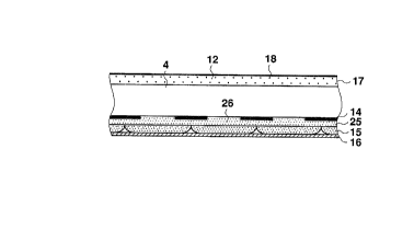
Fig, 1 is a schematic enlarged sectional view of the
structure of a phosphor screen according to the present
invention, which has antistatic and selective light absorb-
ing functions similar to those of a conventional antistatic
type selective light absorption film.
The antistatic type selective light absorption film 17
produced by dispersing and mixing the conductive filler
particles 18 in with the porous silica (SiO2) film 12 is
formed over the outer surface of the face plate 4. On the
inner surface of the face plate 4 are formed the black light
absorbing layer 14, the BGR phosphor layer 15 and the
metal-backed layer 16 in the same way as in a conventional
phosphor screen. The present invention is different from a
conventional phosphor screen in that a selective light
absorption layer 25 having optical characteristics common to
the three colors B, G and R is provided betw~en the inner
surface of the face plate 4 and the BGR phosphor layer 15
provided on the inner surface of the face plate 4.
- 35 -
206~792
As the selective light absorption layer 25, a seiective
lisht absorption layer having a light absorption character-
istic with one main absorption peak and two sub absorption
peak~ as shown by the spectral transmittance distribution
(I) in Fig. 17, a selective light absorption layer having a
light absorption characteristic with one main absorption
peak and one sub absorption peak as shown by the spectral
transmittance distribution (II) in Fig. 18, or the like is
selected with due consideration for the light emission
characteristics of the BGR phosphor layer 15 and the like.
In order to form the selective light absorption layer
25, after the black light absorbing layer 14 is formed over
the inner surface of the face plate 4 by a photo-engraving
process as in the related art, a coating liquid obtained by
dispersing and mixing the particles 26 of an inorganic or
organic pigment or dye in with a binder is applied to the
black light absorbing layer 14. It has been confirmed from
experiments that the selective light absorption layer 25
needs to have a thickness of not less than 0.1 ~m in order
to enhance the contrast. If the thickness is less than 0.1
~m, the contrast enhancing effect is greatly diminished.
This is considered to be because if the thickness is
reduced, the external light absorbing action changes from
volume absorption to area absorption.
- 36 -
2068792
Since it is difficult to obtain the desired optical
characteristics described above by adding only one kind of
particle 26 of an inorganic or organic pigment or dye to the
binder, a mixture of two to four kinds of inorganic or
organic pigment or dye is used. In order to form the
selective light absorption layer 25 of a uniform film, the
average particle diameter of the particles 26 of inorganic
or organic pigment or dye added to the binder is preferably
not more than 1.0 ~m.
After forming the selective light absorption layer 25
over the inner surface of the face plate 4, the BGR phosphor
layer 15 and the metal-backed layer 16 are formed on the
selective light absorption layer 25 by the same method as in
the related art. As a result, the optical characteristics
of the selective light absorption layer 25 are common to the
light emitted from the BGR phosphor layer 15.
The functional film (9) in Table 3 is the functional
film formed over the outer surface of the face plate 4 in
this embodiment. The measured film strength was 9H - 70
times. Since the antistatic function and the selective
light absorbing function of the phosphor screen as a whole
are equivalent to those of the conventional functional film
(2) shown in Table 1, the film strength of the functional
fi;m (9~ is g.eat'y i~..rrcved in c~mFcriscn wi h ~he r'~
strength 8H - 50 times of the functional film (2).
2068792
Table 3
Face Plate Film strength of
the ou~er urface
Outer surface Inner Pencil Eraser
(embodiment) surface strength test
(times)
(9) Silica (SiO2) film Selective 9H 70
+ conductive filler light
(single layer) absorbing
layer
(10) Silica (SiO2) film Selective 8H 50
+ conductive flller light
+ low-refraction absorbing
material layer
(single layer)
(11) First layer Selective 7H 40
(silica (SiO2) film light
+ conductive filler absorbing
+ high-refractio layer
material) +
second layer
(silica (SiO2) film
+ conductive filler
+ low-refraction
material)
(double layer)
(12) Silica (SiO2) film Neutral 9H 70
+ conductive flller filter
(single layer) layer
(13) Silica (SiO2) film Neutral 8H 40
+ conductive flller filter
+ low-refraction layer
: material
(single layer)
(14) First layer Neutral 7H 30
(silica (SiO2) film filter
+ conductive filler layer
+ high-refractior
material) +
second layer
(silica (SiO2) film
+ conductive filler
low-refraction
material~
(double layer)
- 38 -
2068792
Second Embodiment
Fig. 2 is a schematic enlarged sectional view of the
structure of a phosphor screen according to the present
invention, which has an antistâtic, selective light a~scrb-
ing and reflectivity lowering functions similar to those of
â conventional optical monolayer antistatic type selective
light absorption and low-reflection film. The
low-refraction layer 21 having a constant refractive index
and film thickness which is produced by dispersing and
mixing the conductive filler particles 18 for imparting an
antistatic function and the ultrafine particles 22 of
magnesium fluoride (MgF2) for lowering the refractive index
in with the porous silica (SiO2) film 12 is formed over the
outer surface of the face plate 4. The low-refraction layer
21 functions as an antistatic type low-reflection film. On
the inner surface of the face plate 4, the selective light
absorption layer 25 having optical characteristics common to
the three colors B, G and R is provided between the inner
surface of the face plate 4 and the BGR phosphor layer 15
provided on the inner surface of the face plate 4 in the
same way as in the first embodiment.
_ 3C _
2068792
The optical characteristics of the selective light
absorption layer 25 and the method of producing it are
exactly the same as in the first embodiment. In the
phosphor screen of the second embodiment, an antistatic
function and an optical monolayer low-refraction function
are imparted to the outer surface of the face plate 4 while
a selective light absorbing function is imparted to the
inner surface of the face plate. In this way, the phosphor
screen as a whole has functions similar to those of a
conventional optical monolayer antistatic type selective
light absorption and low-reflection film.
The functional film (10) in Table 3 is the functional
film formed over the outer surface of the face plate 4 in
this embodiment. The measured film strength was 8H - 50
times. Since the functions of the phosphor screen as a
whole are equivalent to those of the conventional optical
monolayer antistatic type selective light absorption and
low-reflection film (3) shown in Table 1, the film strength
of the functional film (10) is greatly improved in compari-
son with the film strength of 5H - 20 times of the
functional film (3). Since the film strength expressed by a
pencil hardness of 7H and an eraser test of not less than 3G
times produces almost no problem from the point of view of
hc~.e use G ' a cclcr te'e~i~slcn set, t can be sa~'d that the
functional film in the second embodiment has a sufficient
- 4C -
2Q68~92
mechanical strength for practical use.
Third Embodiment
Fig. 3 is a schematic enlarged sectional view of the
structure of a phosphor screen according to the present
invention, which has functions similar to those of a conven-
tional optical multilayer antistatic type selective light
absorption and low-reflection film. An optical multilayer
antistatic type low-reflection film which is composed of the
high-refraction layer 23 and the low-refraction layer 21
each havin~ constant refractive index and film thickness is
formed over the outer surface of the face plate 4.
The high-refraction layer 23 is produced by dispersing
and mixing the conductive filler particles 18 and the
ultrafine particles 24 of a high-refraction material for
raising the refractive index in with the porous silica
(SiO2) film 12 so as to have a constant refractive index and
film thickness. As the ultrafine particles 24 of a
high-refraction material, the particles of titanium oxide
(TiO2), tantalum oxide (Ta205), zirconium oxide (ZrO2), zinc
sulfide (ZnS), or the like which have an average particle
diameter of not more than 1000 A are used in the same way as
in the related art. Since the low-refraction iayer 21 has
the same structure as the low-refraction layer 21 in the
second embodiment, which ccnst tu.es the anti st2~- C _ype
low-reflection film, explanation thereof will be omitted.
- 41 -
2e68792
On the inner surface of the face plate 4, the selective
light absorption layer 25 having optical characteristics
common to the three colors B, G and R is provided between
the inner surface of the face plate 4 and the BGR phosphor
layer 15 provided on the inner surface of the face plate 4
in the same way as in the first and second embodiments.
The optical characteristics of the selective light absorp-
tion layer 25 and the method of producing it are exactly
the same as in the first and second embodiments. In the
phosphor screen of the third embodiment, an antistatic
function and an optical multilayer low-refraction function
are imparted to the outer surface of the face plate 4 while
a selective light absorbing function is imparted to the
inner surface of the face plate. In this way, the phosphor
screen as a whole has functions similar to those of a
conventional optical multilayer antistatic type selective
light absorption and low-reflection film. In the case of
the optical multilayer low-reflection film which is composed
of a combination of the high and low-refraction layers, the
larger the number of layers is, the lower the surface
reflectivity which is obtained as in a conventional one.
However, since the fine control and the suppression of the
variation of the film thickness of such a film formed by
spin C02ti~g are difficult, r he number of layers will be
limited to between two and four.
- 42 -
2068792
The functional film (11) in Table 3 is the functional
film formed over the outer surface of the race p~ate 4 in
this embodiment. The measured film strength was 7H - 40
times. Since the functions of the phosphor screen as a
whole are equivalent to those of the conventional optical
multilayer antistatic type selective light absorption and
low-reflection film (4) shown in Table 1, the film strength
of the functional film (11) is greatly improved in compari-
son with the film strength of 3H - 10 times of the function-
al film (4). Since the film strength of 7H -30 times
produces almost no problem from the point of view of home
use of a color television set, as described above, it can be
said that the functional film in the third embodiment has a
sufficient mechanical strength for practical use.
Although an antistatic function is imparted to the
functional films in the first to third embodiments by
dispersing and mixing the conductive filler particles 18 in
with the porous silica (SiO2) film 12, the present invention
is not restricted thereto. It is possible to form function
films 28 to 30 having conductivity by using a porous silica
film 27 containing water as a base and without adding the
conductive filler particles 18 thereto as
in the fourth to sixth embodiments shown in Figs. 4 to 6,
respectively. The porous silica film 27 containing water is
- 43 -
2068792
prod~lced by taking in the water content in the porous silica
(Sio2) film 12 and in the air.
Seventh Embodiment
Fig. 7 is a schematic enlarged sectional view of the
structure of a phosphor screen according to the present
invention, which has functions similar to those of a conven-
tional antistatic type uniform light absorption film. This
embodiment is different from a conventional phosphor screen
in that a neutral filter layer 31 for uniformly controlling
the transmittance of the light emitted from the BGR phosphor
layer 15 is provided between the inner surface of the face
plate 4 and the BGR phosphor layer 15 provided on the inner
surface of the face plate 4.
The materials for the neutral filter layer 31 are
selected so as to have a uniform spectral transmittance in
the visible light region similar to the spectral
transmittance distribution ~I) in Fig. 17.
In order to form the neutral filter layer 31, after the
black light absorbing layer 14 is formed on the inner
surface of the face plate 4 by a photo-engraving process as
in the related art, a coating liquid obtained by dispersing
and mixins the particles 32 of an inorganic or organic
pigment or dye in with a binder is applied to the black
1 sht absorblng layer 14. It has been confirmed from
experiments that the neutral filter ,ayer 25 r.eeds to have a
- 44 -
2068792
thickness of not less than 0.1 um in order to enhance the
contrast. If the thickness is less than 0.1 ~m, the con-
trast enhancing effect is greatly diminished. This is
considered to be because if the thickness is reduced, the
external light absorbing action changes from volume
absorption to area absorption.
Since it is difficult to obtain the desired optical
characteristics described above by adding only one kind of
particle 32 of an inorganic or organic pigment or dye to the
binder, a mixture of two to four kinds of inorganic or
organic pigment or dye is used. In order to form the
neutral layer 31 of a uniform film, the average particle
diameter of the particles 32 of inorganic or organic pigment
or dye added to the binder is preferably not more than 1.0
~m.
After forming the neutral filter layer 31 over the
inner surface of the face plate 4, the BGR phosphor layer 15
and the metal-backed layer 16 are formed on the neutral
filter layer 31 by the same method as in the related art.
As a result, the neutral filter layer 21 uniformly controls
the transmittance of the light emitted from the BGR phosphor
layer 15.
The functional film (12) in Table 3 is the functional
f-lm formed over the outer surface of the face plate 4 in
this embodiment. The measured film strength was 9H - 70
- 45 -
2068792
times. Since the functions of the phosphor screen as a
whole are equivalent to those of the conventional functional
film (6) shown in Table 2, the film strength of the func-
tional film (12) is greatly improved in comparison with the
film strength of 8H - 40 times of the functional film (6).
Eighth Embodiment
Fig. 8 is a schematic enlarged sectional view of the
structure of a phosphor screen according to the present
invention, which has antistatic, uniform light absorbing and
reflectivity lowering functions similar to those of a
conventional optical monolayer antistatic type uniform light
absorption and low-reflection film. The low-refraction
layer 21 having constant refractive index and film thickness
which is produced by dispersing and mixing the conductive
filler particles 18 for imparting an antistatic function and
the ultrafine particles 22 of magnesium fluoride (MgF2) for
lowering the refractive index in with the porous silica
(SiO2) film 12 is formed over the outer surface of the face
plate 4. The low-refraction layer 21 functions as an
antistatic type low-reflection film. On the inner surface of
the face plate 4, the neutral filter layer 31 for uniformly
controlling the transmittance of the light emitted from the
BGR phosphor layer is provided between the inner surface of
the face plate 4 and the BGR phosphor layer 15 provided on
- 46 -
2068792
the inner surface of the face plate 4 in tAe same way as in
the seventh embodiment.
The optical characteristics of the neutral filter layer
31 and the method of producing it are exactly the same as in
the seventh embodiment. In the phosphor screen of the
eighth embodiment, an antistatic function and an optical
monolayer low-refraction function are imparted to the outer
surface of the face plate 4 while a uniform light absorbing
function is imparted to the inner surface of the face plate.
In this way, the phosphor screen as a whole has functions
similar to those of a conventional optical monolayer
antistatic type uniform light absorption and low-reflection
film.
The functional film (13) in Table 3 is the functional
film formed over the outer surface of the face plate 4 in
this embodiment. The measured film strength was 8H - 50
times. Since the functions of the phosphor screen as a
whole are equivalent to those of the conventional optical
monolayer antistatic type uniform light absorption and
low-reflection film (7) shown in Table 2, the film strength
of the functional film (13) is greatly improved in compari-
son with the film strength of 6H - 15 times of the function-
! al film (7). Since the film strength expressed by a pencil
hardness of 7H and an eraser test of not less than 30 times
produces almost no problem 'ro.m the point of view of home
2068792
use of a color .elevision se~, it can be said that thefunctional film in the second embodiment has a sufficient
mechanical strength for practical use.
Ninth Embodiment
Fig. 9 is a schematic enlarged sectional view of the
structure of a phosphor screen according to the present
invention, which has functions similar to those of a conven-
tional optical multilayer antistatic type uniform light
absorption and low-reflection film. An optical multilayer
antistatic type low-reflection film which is composed of the
high-refraction layer 23 and the low-refraction layer 21
each having constant refractive index and film thickness is
formed over the outer surface of the face plate 4.
The high-refraction layer 23 is produced by dispersing
and mixing the conductive filler particles 18 and the
ultrafine particles 24 of a high-refraction material for
raising the refractive index in with the porous silica
(SiO2) film 12 so as to have constant refractive index and
film thickness. As the ultrafine particles 24 of a
high-refraction material, the particles of titanium oxide
(TiO2), tantalum oxide (Ta205), zirconium oxide (ZrO2), zinc
sul~ide (ZnS), or the like which have an average particle
diameter of not more than 1000 A are used in the same way as
in the related art. Since the low-refraction layer 21 has
the s~me structure as the 'ow-refraction layer 21 in the
- 48 -
2068792
eighth embodiment, which constitutes the antistatic type
low-reflection film, explanation thereof will be omitted.
On the inner surface of the face plate 4, the neutral
filter layer 31 for uniformly controlling the transmittance
of the light emitted from the BGR phosphor layer 15 is
provided between the inner surface of the face plate 4 and
the BGR phosphor layer 15 provided on the inner surface of
the face plate 4 in the same way as in the seventh and
eighth embodiments. The optical characteristics of the
neutral filter layer 31 and the method of producing it are
exactly the same as in the seventh and eighth embodiments.
In the phosphor screen of the ninth embodiment, an
antistatic function and an optical multilayer low-refraction
function are imparted to the outer surface of the face plate
4 while a uniform light absorbing function is imparted to
the inner surface of the face plate. In this way, the
phosphor screen as a whole has functions similar to those of
a conventional optical multilayer antistatic type selective
light absorption and low-reflection film. In the case of
the optical multilayer low-reflection film which is composed
of a combination of high and low-refraction layers, the
larger the number of layer is, the lower the surface
reflectivity which is obtained in the same way as in a
conventional one. However, since the fine control and the
suppression of the variation of the film thickness of such a
- 49 -
2068792
film formed by spin coating are difficult, the number of
layers will be limited to between two and four.
The functional film (14) in Table 3 is the functional
film formed over the outer surface of the face plate 4 in
this embodiment. The measured film strength was 7H - 30
times. Since the functions of the phosphor screen as a
whole are equivalent to those of the conventional optical
multilayer antistatic type uniform light absorption and
low-reflection film (8) shown in Table 2, the film strength
of the functional film (141) is greatly improved in compari-
son with the film strength of 4H - S times of the functional
film (8). Since the film strength of 7H -30 times produces
almost no problem from the point of view of home use of a
color television set, as described above, it can be said
that the functional film in the third embodiment has a
sufficient mechanical strength for practical use.
Although an antistatic function is imparted to the
functional films in the first to third embodiments by
dispersing and mixing the conductive filler particles 18 in
with the porous silica (Sio2) film 12, the present invention
is not restricted thereto. It is possible to form function
films 28 to 30 having conductivity by using a porous silic&
film 27 containing water as a base and without adding the
conducti~e flller particles 18 thereto as in the tenth to
twelfth embodiments shown in Figs. 10 to 12, respectively.
- 5~ -
21~Ç8792
The porous silica film 27 containing water is produced by
taking in the water content in the porous silica (SiO2) film
12 and in the air.
As described above, according to the present invention,
among the various functions of the conventional functional
film formed over the outer surface of a face plate, the
selective light absorbing function is transferred to the
selective light absorption layer provided between the inner
surface of the face plate and the BGR phosphor layer provid-
ed on the inner surface of the face plate. It is therefore
possible to reduce the number of kinds and amount of differ-
ent material added to the functional film provided over the
outer surface of the face plate. Since the strength of the
functional film is lowered to a large extent when a func-
tional film having various functions is provided over the
face plate, the present invention is capable of ameliorating
this defect without lowering the functions of the functional
film. Consequently, it is possible to produce a
high-quality color cathode ray tube which is unlikely to
produce problems such as the problems of scratching the
functional film formed over the outer surface of the face
plate during use of the color television set, impairing the
external appearance by the peeling-off of the functional
film and influencing the defir.ition of the im2se. The
selective light absorption layer is realized by applying the
-- ~i --
2068792
particles of inorganic or organic pigment or dye to the
inner surface of the face plate.
It is also possible to produce desired optical charac-
teristics by using a mixture of the particles of at least
two kinds of inorganic or organic pigment or dye. If the
average particle diameter of the particles of inorganic or
organic pigment or dye is set at not more than 1.0 ~m, the
selective light absorption layer formed from a uniform film
is realized. If the spectral transmittance of the selective
light absorption layer has at least two absorption peaks, it
is possible to make the main absorption peak coincident with
a range of a relatively high spectral luminous efficacy of
human eyes and use a sub absorption peak as a means for
controlling the original color of the phosphor screen
itself. By providing an antistatic film, no discharge is
generated when the viewer approaches the cathode ray tube
even if it is used at a high voltage. In addition, if an
optical monolayer low-reflection function as well as the
selective light absorbing function is imparted to the
cathode ray tube, a multi-function color cathode ray tube
having both functions is realized. By providing an optical
multilayer low-reflection film produced from between two and
four optical interference films, a lower reflectivity is
obtained. In add_tion, a multi-function color cathode ray
- 52 -
206~792
tube having both the reflectivity lowering function and the
antistatic function can also be realized.
According to the present invention, among the various
functions of the conventional functional film formed over
the outer surface of a face plate, the uniform light absorb-
ing function is transferred to the neutral filter layer
provided between the inner surface of the face plate and the
BGR phosphor layer provided on the inner surface of the face
plate. It is therefore possible to reduce the number of
kinds and amount of different material added to the func-
tional film provided over the outer surface of the face
plate. Since the strength of the functional film is lowered
to a large extent when a functional film having various
functions is provided over the face plate, the present
invention is capable of ameliorating this defect without
lowering the functions of the functional film. Consequent-
ly, it is possible to produce a high-quality color cathode
ray tube which is unlikely to produce problems such as the
problems of scratching the functional film formed over the
outer surface of the face plate during use of the color
television set, impairing the external appearance by the
peeling-off of the functional film and influencing the
definition of the image.
It is possible to rorm a neutra' filter layer from the
2Q68792
particles of inorganic or organic pigment or dye by a
coating process, for example.
If the neutral filter layer is formed from a mixture of
the particles of at least two kinds of inorganic or organic
pigment or dye, the optical characteristics which are
difficult to realize using the neutral filter layer formed
from the particles of one kind of inorganic or organic
pigment or dye are obtained.
If the average particle diameter of the particles of
inorganic or organic pigment or dye is set at not more than
1.0 ~m, the neutral filter layer formed from a uniform film
is realized.
By using graphite or carbon particles as inorganic
pigment particles, it is easy to realize a color cathode ray
tube having almost uniform spectral transmittance in the
visible light region.
By providing an antistatic film on the outer surface of
the face plate, it is possible to prevent inconvenience
caused by discharges generated when the viewer approaches
the cathode ray tube.
By providing an optical monolayer low-reflection film
over the outer surface of the face plate, a multi-function
color cathode ray tube having a reflectivity lowering func-
tion as well as the uniform lisht absorbing function is
realized.
- 54 -
2Q68792
By providing an optical multilayer low-reflection film
produced from between two and four optical interference
films, a multi-function color cathode ray tube having the
optical multilayer reflectivity lowering function as well as
the uniform light absorbing function is realized.
In addition, if fine conductive particles are mixed
with the low-reflection film, an antistatic function is
added, thereby realizing a more excellent multi-function
color cathode ray.
While there has been described what are at present
considered to be preferred embodiments of the invention, it
will be understood that various modifications may be made
thereto, and it is intended that the appended claims cover
all such modifications as fall within the true spirit and
scope of the invention.