Note: Descriptions are shown in the official language in which they were submitted.
TITLE OF THE INVENTION
RETAINER FOR USE IN PIPE JOINTS
BACKGROUND OF THE INVENTION.
The present invention relates 'to a retainer
for use in pipe joints, and more particularly to a
retainer for holding an annular gasket in position
between opposed end faces of a pair of tubular joimt
members.
Description of the Prior Art
Retainers are already known fo.r holding an
annular gasket in position between opposed end faces
of a pair of tubular joint members. The known retainer
comprises an annular end wall, a cylindrical side wall
extending outward from the end wall substantially
perpendicular thereto, and a plurality of holding legs
extending further outward from the cylindrical. side
wall and having means engageable with the joint member
(see Examined Japanese Patent Publication HEI 2-
62756).
The gasket for use in pipe joints needs t o
be replaced, for example, when becoming impaired in
sealing effect. However, the conventional reta.ine~
is so shaped as to surround the entire gasket with 'the
annular end wall and the cylindrical side wall, with
20~~~~8
the result that the gasket can not be placed into or
removed from the retainer as attached to the end portion
of the joint member. Accordingly, the replacement of
the gasket requires the cumbersome procedure of removing
the retainer from the joint member. Furthermore, after
pipes have been joined to the joint for piping, it is
likely that only a small clearance will be formed
between the opposed.ends of the two joint members even
when the joint members are unfastened from each other.
It is then impossible to change the gasket as installed
in this state, so that there arises a need to cut the
piping for changing the gasket and thereafter weld the
piping, or to replace the entire piping assembly
including the joint and the pipes on opposite sides
by a new one. Nevertheless, the replacement of the
entire piping assembly is very cumbersome, takes much
time and is uneconomical.
To overcome the above problem, we have
proposed a retainer which c:ompxises an annular body
positionable on one side face of a gasket and having a
pair of support lugs projecting from the,ou'ter peri-
phery of the annular body at positions dividing -the
circumference thereof into two equal. portions. The
support lugs are opposed to each other for holding an
end portion of a joint member therebetween, and a
CA 02068968 2002-12-31
25088-103
gasket support is provided on only one of the divided
peripheral portion of the body (see Examined Japanese Patent
Publication HEI 1-28398).
The proposed retainer is so adapted that the
gasket can be replaced with the retainer attached to the end
portion of the joint member, whereas the retainer has the
problem that the gasket is liable to slip off the retainer
and difficult to handle when the retainer is stored or
transported with the gasket fitted therein since the gasket
is merely held by the gasket support which is provided on a
part of the lower half of the retainer body outer periphery.
SUMMARY OF THE INVENTION
The main object of the present invention is to
provide a retainer fox use in pipe joints which permits easy
replacement of the gasket even after pipes have been joined
to the joint and which is adapted to hold the gasket as
fitted therein without the likelihood of the gasket slipping
off readily.
The present invention provides a retainer for use
in a pipe joint having a pair of tubular joint members for
holding an annular gasket in position between opposed end
faces of the joint members, the retainer comprising an end
wall portion positionable on one side face of the gasket, a
cylindrical portion extending from the end wall portion
substantially perpendicular thereto for preventing the
gasket from moving radially thereof, and an engaging portion
provided on the cylindrical portion and engageable with an
end portion of one of the joint members, the end wall
portion being formed with a cutout, characterized in that
the cutout subtends an angle of 160 to 180 degrees at the
3
CA 02068968 2002-12-31
25088-103
center of the end wall portion for passing the gasket
therethrough.
The gasket can be placed into or removed from the
retainer through the cutout formed in the end wall portion
and can therefore be replaced with the retainer attached to
the end portion of the joint member. When fitted in the
retainer, the gasket is prevented by the cylindrical portion
from moving radially thereof, with one side face thereof
held by the retainer end wall portion, and is therefore
precluded from slipping off the retainer readily.
Thus, the gasket can be replaced with the retainer
of the invention attached to the joint member end portion,
so that it is easy to replace the gasket even after pipes
have been joined to the joint. When fitted in the retainer,
the gasket will not readily slip off the retainer. The
retainer is therefore
4
'~06~~~~
convenient to store or transport.
BRIEF DESCRIPTION OF THE DRAWING S
FIG. 1 is a view.in longitudinal section of
a pipe joint wherein a retainer embodying the invention
is used;
FIG. 2 i~ a fragmentary exploded perspective
view of FIG. 1;
FIG. 3 is a front view of the retainer;
FIG. 4 is a view in section taken along the
line 4-4 in FIG. 3; and
FTG. 5 is a side elevation of an assembly
including the retainer to show how to remove a gasket.
DESCRIPTION OF THE PREFERRED EMBODIMENT
An embodiment of the invention will be
described below with reference to the accompanying
drawings. In the following description, the terms
"right" and "left" refer to the right-hand side and
left-hand side of FIG. l, respectively.
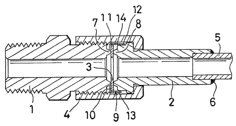
Referring to, FIG. 1, the x-ight end face of
a first tubular joint member 1 is butted against the
left end face of a second tubular. joint member 2, with
an annular gasket 3 held therebetween and retained on
the left end of the second joint member 2 by a retainer
The second joint member. 2 is fastened to the first
joint~member 1 by a nut 4 fitted around the second
'~Q~$~~~
joint member 2 and screwed on the first joint member 1.
A pipe 5 is inserted into the second joint member 2
from its right end and secured to the member 2 by a weld
6. The butting end faces of the first and second joint
members 1 and 2 are respectively formed with annular
ridges 7, 8 semicircular in cross section for holding
the gasket 3 therebetween.
With reference to FIG. 2, the retainer 9 is
made of a thin metal plate and comprises an end wall
l0 portion 10 positionable on one side face of the gasket 3,
a cylindrical portion 1.1 extending from the end wall
portion 10 substantially perpendicular thereto, and an
engaging portion provided on the forward end (right end?
of the cylindrical portion 11 and engageable with the
left end of the second joint member 2. The end wall
portion 10 has a cutout l5.
The end wall portion 10 is in the form of an
annular wall which is partly cut out along its circum-
ference to form -the cutout 15 subtending an angle of
about 170 degrees at the~center of the portion 10. '.rhe
gasket 3 can be brought into and out of the retainer 9
through the cutout 15. The cutout 1.5 is formed only in
the end wall portion 10 and riot provided in the cyl.:indri-
cal portion 1l.
Two incisions are formed in the part of the
-6-
cylindrical portion 11 toward its forward end at each
of positions dividing the circumference of the portion
11 unto three equal portions, whereby large circular-
arc portions 13 and small. circular-are portions 14 are
formed as arranged alternately. The small circular-arc
portions 14 are slightly bent inward and each have
at its outer end a support projection 12 for holding
the outer surface of the left end portion of the second
joint member 2. The engaging portion comprises these
three support projections 12. Since the retainer 9 is
thin and made of metal, the engaging portion has
elasticity.
When.the engagzng portion of the retainer 9
is fitted to the second joint member 2, the engaging
portion is expanded outward to elastically engage the
left end outer surface of the second joint member 2,
whereby the gasket 3 as retained in the retainer 9 is
held to the left end of,the second joint member 2.
When the nut 4 fitted around the second joint member 2
and screwed on the first joint member 1. is tightened
up, the annular ridge 7 of the first joint member 1 and
the annular ridge 8 of the second joint member 2 axe
pressed against the respective surfaces of the gasket 3
to provide a fluidtight joint.
The procedure for replacing the gasket 3 will
~~68~s8
be described with .reference to FIG. 5.
First, the nut 4 is loosened and removed from
the first joint member 1. This provides a small
clearance between the opposed end faces of the two joint
members l, 2, rendering the retainer 9 slightly movable
axially leftward. The retainer 9 is -then moved leftward
to form a clearance between the end wall portion 10 of
the retainer 9 and the left end face of the second
joint member 2. This state is shown in FIG. 5. The
gasket 3 can be withdrawn by tilting the gasket 3 in
the clearance and pulling the gasket obli,guely leftward
through the cutout 15 of the retainer 9. A new gasket
3 is then inserted as inclined into the retainer 9
through the cutout 15. Thus, the gasket 3 can be held
in the retainer 9.
Although the engaging portion comprises three
support projections 12 according to the above embodi-
menu, the support projections are not limited to three
in number. Alternatively, the engaging portion may be
in the form of a ring, and the retainer may be cut
axially thereof to impart elasticity to the engaging
portion.
Although the end wall portion 10 is in the
form of an annular wall which is cut out along a portion
of its circumference subtending an angle of about 170
_g_
degrees at the center of 'the end wall portion, t he cut-
out is not limited to this size provided that 'the
gasket 3 can be passed through the cutout 15 when the
two joint members l, 2 are. unfastened from each other
and that the gasket 3 as fitted in the retainer 9 will
not readily slip off. The center angle to be subtended
by the cutout is determined in view of the outside
diameter, thickness and material of the. gasket and is
preferably 160 to 180 degrees.