Language selection

Search

Patent 2068983 Summary

Third-party information liability

Some of the information on this Web page has been provided by external sources. The Government of Canada is not responsible for the accuracy, reliability or currency of the information supplied by external sources. Users wishing to rely upon this information should consult directly with the source of the information. Content provided by external sources is not subject to official languages, privacy and accessibility requirements.

Claims and Abstract availability

Any discrepancies in the text and image of the Claims and Abstract are due to differing posting times. Text of the Claims and Abstract are posted:

  • At the time the application is open to public inspection;
  • At the time of issue of the patent (grant).
(12) Patent Application: (11) CA 2068983
(54) English Title: TOOL FOR REMOVAL AND REPLACEMENT OF LIGHT BULBS
(54) French Title: OUTIL POUR LE REMPLACEMENT D'AMPOULES
Status: Deemed Abandoned and Beyond the Period of Reinstatement - Pending Response to Notice of Disregarded Communication
Bibliographic Data
Abstracts

English Abstract


TOOL FOR REMOVAL AND REPLACEMENT
OF LIGHT BULBS
ABSTRACT OF THE INVENTION
A tool for the removal of a light bulb from a remote socket
consists of a flexible cup fitted over one end of a hollow rod.
The other end of the rod is fitted to a flexible elastomeric
bellows adapted to expel its inner air through the cup to allow
any object such as a light bulb to be gripped by the cup surface
when the bellows is released.


Claims

Note: Claims are shown in the official language in which they were submitted.

THE EMBODIMENTS OF THE INVENTION IN WHICH AN
EXCLUSIVE PROPERTY OR PRIVILEGE IS CLAIMED
ARE DEFINED AS FOLLOWS:
1. A tool for the removal and replacement of light bulbs
from their sockets comprising in combination;
a flexible cup fixed to a rod adapted to be twisted by an
operatorwhen the cup has beenfitted around a light bulb;
thereby to unthread said bulb from a socket.
2. A tool as in claim 1 wherinsaid rod is hollow and fits
over a funnel shaped hollow extension of a bottom portion of
said cup and whereinsaid rod has an end remote from the end
attached to said cup attached to a bellows means whereby
operation of said bellows forces air through said rod and out
of said cup or in the alternative when the bellows is released,
createsdownward pressure into the cup and into the bellows
of air suction.
3. A tool as in claim 2 wherein the cup is made of elastomeric
material such as soft rubber.
4.A tool as in claim 1 wherein the cup has a soft roughened
surface on its inner side to grip a glass light bulb surface.

Description

Note: Descriptions are shown in the official language in which they were submitted.


~ ~ TOOL FOR REMOVAL AND REPLACEMENT OF LIGHT BULBS
2~6898~
FIELD OF INVENTION
The present invention discloses a flexible member held
aloft on a rigid hollow rod for enclosing a light bulb within
its socket. By imp~rting a twisting motion to the rod, an
operator standing below the bulb with the flexible member
surrounding the bulb, can unscrew the bulb from its socket in
an overhead fixture.
.
PRIOR ART
In industrial sites where overhead light bulbs are in use
and where long step ladders are awkward to use, a cage-like
device held on a long rod has been used to enclose the bulb and~
is used to impdrt the twisting action for removal of the bulb.
A cushion material i5 often fitted to the inner sides of the
claws of the cage to prevent breakage of the glRss of the bu]b
when being removed or replaced.
It is known that many household accidents are caused by
people climbing on chairs or ladders to reach objects otherwise
out of their reach from a floor surface. It is known that many
light fixtures are difficult to access without the use of a
ladder or climbing assist such as a chair. For old people the
danger of climbing to change light bulbs is very great and with
the recent design of apartments specifically made for older
people with saftey in mind, the need for a tool to easily change
a light bulb for a fixture has become apparent.

r
OBJECT OF THE INVENTION ~ 0 ~ ~ ~ 8 3
The principal object of the invention is therefore to
provide a tool having a flexible member thereon to surround a
light bulb and which when twisted on t.he bulb will unscrew it
from the fixture. Another object of the invention is to position
the flexible member on a pole thereby allowing a person to use
the flexible member from a position remote from the bulb. Another
object of the invention is to use a hollow rod or pole with the
inner body of the flexible member having and opening therein.--:
I`he flexible member is adapted to interfit over one hollow end of
the rod to allow air passage between the rod and the flexible member.
A bellows member is adapted to interfit over the lower end of the
hollow rod to permit the passage of air into and from the hollow
rod.
SUMMARY OF THE INVENTION
A tool for the removal of a light bulb consists of an
elastomeric flexible cup adapted to interfit over the roundecl
portion of a light bulb and has an opening therein fixed over one
end of a hollow rod. A bellows is fixed to the other end of the
hollow rod to allow passage of air therethrough to and from the
flexible cup. The inner face side of the flexible cup has a soft
elastomeric surface thereon to grip the surface of the light bulb.
OPERATION OF THE DEVICE
To remove a light bulb wi~h the device, the bellows is
depressed to expel the air from it and after the cup has been
fitted over the bulb the bellows is allowed to return to normal
--3--
.~ :

2~8983
-l~ereby a vacilum effect is created in the system and in the space
between the cup and the rod opening thereby helping to pull the
bulb into engagement with the gripping surface of the cup. The
rod i9 then twisted until the bulb threads are freed from the
socket and the tool and bulb combination can be lifted away from
the socket without the bulb falling out of the cup. To replace
a bulb it is placed into the cup while the bellows is depressed
and then the bellows is released to impart a vacuum assist to the
gripping action of the cup surface. The combination, tool and bulb,
is then lifted to the socket where, by twisting the rod, it is
screwed into place. When the bulb is in place in the socket the
bellows is depressed to break the vacuum and thereby releases the
cup from the bulb.
' .
IN THE DRAWINGS
With the foregoing objects in view and such advantages or
novel features as may become apparent from consideration of this
disclosure and specification the present invention consists of
the concept which is comprised, embodied and embraced and included
in the methods or use of the methods and arrangements, or any
new use of the foregoing, herein exemplified in the specific
embodiment of the concept, reference being had to the accompanying
drawings.
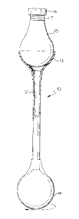
Figure 1 is a view of the tool in use showing the cup in section
over a bulb and attached to the rod of the device.
Figure 2 is a perspective bottom view of the flexible cup attached
to a rod and shows the rough inner gripping surface of the flexible
cup .
--4--
.

2058983
THE PREFERRED EMBODIMENT OF THE INVENTION
Numeral 10 in Figure 1 designates the tool of the invention
shown in engagement with a light bulb 15 by the gripping ac-tion
of the elastomeric cup 13 as shown also in Figure 2 where the inner
surface of cup 13 is roughened as at 20 to grip the smooth outer
surface of the bulb 15. The cup 13 tapers to a hollow opening
where it is fixed to a hollow rod 12 in a funnel-like configuration.
The hollow rod 12 is open at both ends with the one end aE~resaid
fitted to the cup and the other end open and fitted to an opening
into the interior of a flexible rubber bellows 14. Squeezing of
the bellows 14 will expel air out through rod 12 and when the
bellows is released after the bulb is fitted to cup 13 a vacuum
like action is created to hold the bulb 15 into engagement with
cup 13. The bulb 15 is shown in Figure 1 threaded at 17 into
a socket 16 which is fixed to a wall or ceil-ing.
" ~
`
:. :

Representative Drawing
A single figure which represents the drawing illustrating the invention.
Administrative Status

2024-08-01:As part of the Next Generation Patents (NGP) transition, the Canadian Patents Database (CPD) now contains a more detailed Event History, which replicates the Event Log of our new back-office solution.

Please note that "Inactive:" events refers to events no longer in use in our new back-office solution.

For a clearer understanding of the status of the application/patent presented on this page, the site Disclaimer , as well as the definitions for Patent , Event History , Maintenance Fee  and Payment History  should be consulted.

Event History

Description Date
Inactive: IPC from MCD 2006-03-11
Inactive: Inventor deleted 2002-06-07
Application Not Reinstated by Deadline 1995-11-20
Time Limit for Reversal Expired 1995-11-20
Inactive: Adhoc Request Documented 1995-05-19
Deemed Abandoned - Failure to Respond to Maintenance Fee Notice 1995-05-19
Application Published (Open to Public Inspection) 1993-11-20

Abandonment History

Abandonment Date Reason Reinstatement Date
1995-05-19
Owners on Record

Note: Records showing the ownership history in alphabetical order.

Current Owners on Record
PERRY A. CASTIGLIONE
Past Owners on Record
None
Past Owners that do not appear in the "Owners on Record" listing will appear in other documentation within the application.
Documents

To view selected files, please enter reCAPTCHA code :


To view images, click a link in the Document Description column. To download the documents, select one or more checkboxes in the first column and then click the "Download Selected in PDF format (Zip Archive)" or the "Download Selected as Single PDF" button.

List of published and non-published patent-specific documents on the CPD .

If you have any difficulty accessing content, you can call the Client Service Centre at 1-866-997-1936 or send them an e-mail at CIPO Client Service Centre.


Document
Description 
Date
(yyyy-mm-dd) 
Number of pages   Size of Image (KB) 
Claims 1993-11-19 1 23
Drawings 1993-11-19 1 19
Abstract 1993-11-19 1 10
Descriptions 1993-11-19 4 109
Representative drawing 1998-10-14 1 9
Fees 1994-05-17 2 55
Courtesy - Office Letter 1994-07-18 1 47
PCT Correspondence 1994-05-12 2 42
Courtesy - Office Letter 1994-07-18 1 48