Sélection de la langue

Search

Sommaire du brevet 2068983 

Énoncé de désistement de responsabilité concernant l'information provenant de tiers

Une partie des informations de ce site Web a été fournie par des sources externes. Le gouvernement du Canada n'assume aucune responsabilité concernant la précision, l'actualité ou la fiabilité des informations fournies par les sources externes. Les utilisateurs qui désirent employer cette information devraient consulter directement la source des informations. Le contenu fourni par les sources externes n'est pas assujetti aux exigences sur les langues officielles, la protection des renseignements personnels et l'accessibilité.

Disponibilité de l'Abrégé et des Revendications

L'apparition de différences dans le texte et l'image des Revendications et de l'Abrégé dépend du moment auquel le document est publié. Les textes des Revendications et de l'Abrégé sont affichés :

  • lorsque la demande peut être examinée par le public;
  • lorsque le brevet est émis (délivrance).
(12) Demande de brevet: (11) CA 2068983
(54) Titre français: OUTIL POUR LE REMPLACEMENT D'AMPOULES
(54) Titre anglais: TOOL FOR REMOVAL AND REPLACEMENT OF LIGHT BULBS
Statut: Réputée abandonnée et au-delà du délai pour le rétablissement - en attente de la réponse à l’avis de communication rejetée
Données bibliographiques
Abrégés

Abrégé anglais


TOOL FOR REMOVAL AND REPLACEMENT
OF LIGHT BULBS
ABSTRACT OF THE INVENTION
A tool for the removal of a light bulb from a remote socket
consists of a flexible cup fitted over one end of a hollow rod.
The other end of the rod is fitted to a flexible elastomeric
bellows adapted to expel its inner air through the cup to allow
any object such as a light bulb to be gripped by the cup surface
when the bellows is released.

Revendications

Note : Les revendications sont présentées dans la langue officielle dans laquelle elles ont été soumises.


THE EMBODIMENTS OF THE INVENTION IN WHICH AN
EXCLUSIVE PROPERTY OR PRIVILEGE IS CLAIMED
ARE DEFINED AS FOLLOWS:
1. A tool for the removal and replacement of light bulbs
from their sockets comprising in combination;
a flexible cup fixed to a rod adapted to be twisted by an
operatorwhen the cup has beenfitted around a light bulb;
thereby to unthread said bulb from a socket.
2. A tool as in claim 1 wherinsaid rod is hollow and fits
over a funnel shaped hollow extension of a bottom portion of
said cup and whereinsaid rod has an end remote from the end
attached to said cup attached to a bellows means whereby
operation of said bellows forces air through said rod and out
of said cup or in the alternative when the bellows is released,
createsdownward pressure into the cup and into the bellows
of air suction.
3. A tool as in claim 2 wherein the cup is made of elastomeric
material such as soft rubber.
4.A tool as in claim 1 wherein the cup has a soft roughened
surface on its inner side to grip a glass light bulb surface.

Description

Note : Les descriptions sont présentées dans la langue officielle dans laquelle elles ont été soumises.

~ ~ TOOL FOR REMOVAL AND REPLACEMENT OF LIGHT BULBS
2~6898~
FIELD OF INVENTION
The present invention discloses a flexible member held
aloft on a rigid hollow rod for enclosing a light bulb within
its socket. By imp~rting a twisting motion to the rod, an
operator standing below the bulb with the flexible member
surrounding the bulb, can unscrew the bulb from its socket in
an overhead fixture.
.
PRIOR ART
In industrial sites where overhead light bulbs are in use
and where long step ladders are awkward to use, a cage-like
device held on a long rod has been used to enclose the bulb and~
is used to impdrt the twisting action for removal of the bulb.
A cushion material i5 often fitted to the inner sides of the
claws of the cage to prevent breakage of the glRss of the bu]b
when being removed or replaced.
It is known that many household accidents are caused by
people climbing on chairs or ladders to reach objects otherwise
out of their reach from a floor surface. It is known that many
light fixtures are difficult to access without the use of a
ladder or climbing assist such as a chair. For old people the
danger of climbing to change light bulbs is very great and with
the recent design of apartments specifically made for older
people with saftey in mind, the need for a tool to easily change
a light bulb for a fixture has become apparent.

r
OBJECT OF THE INVENTION ~ 0 ~ ~ ~ 8 3
The principal object of the invention is therefore to
provide a tool having a flexible member thereon to surround a
light bulb and which when twisted on t.he bulb will unscrew it
from the fixture. Another object of the invention is to position
the flexible member on a pole thereby allowing a person to use
the flexible member from a position remote from the bulb. Another
object of the invention is to use a hollow rod or pole with the
inner body of the flexible member having and opening therein.--:
I`he flexible member is adapted to interfit over one hollow end of
the rod to allow air passage between the rod and the flexible member.
A bellows member is adapted to interfit over the lower end of the
hollow rod to permit the passage of air into and from the hollow
rod.
SUMMARY OF THE INVENTION
A tool for the removal of a light bulb consists of an
elastomeric flexible cup adapted to interfit over the roundecl
portion of a light bulb and has an opening therein fixed over one
end of a hollow rod. A bellows is fixed to the other end of the
hollow rod to allow passage of air therethrough to and from the
flexible cup. The inner face side of the flexible cup has a soft
elastomeric surface thereon to grip the surface of the light bulb.
OPERATION OF THE DEVICE
To remove a light bulb wi~h the device, the bellows is
depressed to expel the air from it and after the cup has been
fitted over the bulb the bellows is allowed to return to normal
--3--
.~ :

2~8983
-l~ereby a vacilum effect is created in the system and in the space
between the cup and the rod opening thereby helping to pull the
bulb into engagement with the gripping surface of the cup. The
rod i9 then twisted until the bulb threads are freed from the
socket and the tool and bulb combination can be lifted away from
the socket without the bulb falling out of the cup. To replace
a bulb it is placed into the cup while the bellows is depressed
and then the bellows is released to impart a vacuum assist to the
gripping action of the cup surface. The combination, tool and bulb,
is then lifted to the socket where, by twisting the rod, it is
screwed into place. When the bulb is in place in the socket the
bellows is depressed to break the vacuum and thereby releases the
cup from the bulb.
' .
IN THE DRAWINGS
With the foregoing objects in view and such advantages or
novel features as may become apparent from consideration of this
disclosure and specification the present invention consists of
the concept which is comprised, embodied and embraced and included
in the methods or use of the methods and arrangements, or any
new use of the foregoing, herein exemplified in the specific
embodiment of the concept, reference being had to the accompanying
drawings.
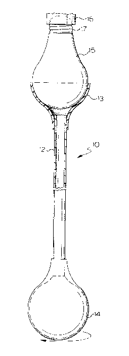
Figure 1 is a view of the tool in use showing the cup in section
over a bulb and attached to the rod of the device.
Figure 2 is a perspective bottom view of the flexible cup attached
to a rod and shows the rough inner gripping surface of the flexible
cup .
--4--
.

2058983
THE PREFERRED EMBODIMENT OF THE INVENTION
Numeral 10 in Figure 1 designates the tool of the invention
shown in engagement with a light bulb 15 by the gripping ac-tion
of the elastomeric cup 13 as shown also in Figure 2 where the inner
surface of cup 13 is roughened as at 20 to grip the smooth outer
surface of the bulb 15. The cup 13 tapers to a hollow opening
where it is fixed to a hollow rod 12 in a funnel-like configuration.
The hollow rod 12 is open at both ends with the one end aE~resaid
fitted to the cup and the other end open and fitted to an opening
into the interior of a flexible rubber bellows 14. Squeezing of
the bellows 14 will expel air out through rod 12 and when the
bellows is released after the bulb is fitted to cup 13 a vacuum
like action is created to hold the bulb 15 into engagement with
cup 13. The bulb 15 is shown in Figure 1 threaded at 17 into
a socket 16 which is fixed to a wall or ceil-ing.
" ~
`
:. :

Dessin représentatif
Une figure unique qui représente un dessin illustrant l'invention.
États administratifs

2024-08-01 : Dans le cadre de la transition vers les Brevets de nouvelle génération (BNG), la base de données sur les brevets canadiens (BDBC) contient désormais un Historique d'événement plus détaillé, qui reproduit le Journal des événements de notre nouvelle solution interne.

Veuillez noter que les événements débutant par « Inactive : » se réfèrent à des événements qui ne sont plus utilisés dans notre nouvelle solution interne.

Pour une meilleure compréhension de l'état de la demande ou brevet qui figure sur cette page, la rubrique Mise en garde , et les descriptions de Brevet , Historique d'événement , Taxes périodiques et Historique des paiements devraient être consultées.

Historique d'événement

Description Date
Inactive : CIB de MCD 2006-03-11
Inactive : Inventeur supprimé 2002-06-07
Demande non rétablie avant l'échéance 1995-11-20
Le délai pour l'annulation est expiré 1995-11-20
Inactive : Demande ad hoc documentée 1995-05-19
Réputée abandonnée - omission de répondre à un avis sur les taxes pour le maintien en état 1995-05-19
Demande publiée (accessible au public) 1993-11-20

Historique d'abandonnement

Date d'abandonnement Raison Date de rétablissement
1995-05-19
Titulaires au dossier

Les titulaires actuels et antérieures au dossier sont affichés en ordre alphabétique.

Titulaires actuels au dossier
PERRY A. CASTIGLIONE
Titulaires antérieures au dossier
S.O.
Les propriétaires antérieurs qui ne figurent pas dans la liste des « Propriétaires au dossier » apparaîtront dans d'autres documents au dossier.
Documents

Pour visionner les fichiers sélectionnés, entrer le code reCAPTCHA :


Pour visualiser une image, cliquer sur un lien dans la colonne description du document. Pour télécharger l'image (les images), cliquer l'une ou plusieurs cases à cocher dans la première colonne et ensuite cliquer sur le bouton "Télécharger sélection en format PDF (archive Zip)" ou le bouton "Télécharger sélection (en un fichier PDF fusionné)".

Liste des documents de brevet publiés et non publiés sur la BDBC .

Si vous avez des difficultés à accéder au contenu, veuillez communiquer avec le Centre de services à la clientèle au 1-866-997-1936, ou envoyer un courriel au Centre de service à la clientèle de l'OPIC.


Description du
Document 
Date
(aaaa-mm-jj) 
Nombre de pages   Taille de l'image (Ko) 
Revendications 1993-11-19 1 23
Dessins 1993-11-19 1 19
Abrégé 1993-11-19 1 10
Description 1993-11-19 4 109
Dessin représentatif 1998-10-14 1 9
Taxes 1994-05-17 2 55
Courtoisie - Lettre du bureau 1994-07-18 1 47
Correspondance reliée au PCT 1994-05-12 2 42
Courtoisie - Lettre du bureau 1994-07-18 1 48