Note: Descriptions are shown in the official language in which they were submitted.
W O 91/052 W PC~r/US90/05404
- ~ - 2Q6~1Q8
METHOD AND APPARATUS FOR ILLUMINATION OF A
LIQUID DROPLET FOUNTAIN TO PRODUCE RAINBOWS
Inventors:
BACXGROUND OF T~ INV~TION
FI~T~n OF INVENTION
The present invention relates to a method to
illuminate a curtain of liquid droplets so that natural
primary and secondary rainbows can be observed continuously
from opposite sides of the droplet curtain.
D~.~CRIPTION OF THE PRIOR ART
The prior art has not attempted to facilitate the
production of actual rainbows through a curtain of liquid
droplets as might be provided by means of a water
fountain. Rather, the prior art has attempted to simulate
rainbows by entirely different optical processes, such as
by using colors produced by absorption rather than
refractive dispersion. The reasons for both the
difficulties experienced by prior art and its resulting
compromises are more easily understood after an explanation
as to the manner in which rainbows are produced in nature.
Against this background, the solution to the problem of
artificial rainbow production provided by the present
invention stands in stark contrast to the efforts of prior
art.
Rainbows are produced in nature when nearly
parallel beams of light from either the sun or the moon are
CA 02069108 1999-03-22
-
W~ ~It052~ t~-:5
sc~tt~d by the nearly sphe~iCal droplets of ~ater in a
rain sho~er, spray fro~ ~ ~aterf-ll, or an ~rtifici~l
source of ~ater droplets such as provided by a ~ater
fount-in The position of ~-ch r~inbow i5 ~t a fi~-d
angul-r dist-nce from th- liqht source aQpro~imatelr 13~ -
d~gr-as for th- prim~rr r-inbo~ ~nd ~ppro~im~tely 129
d-gr-es fcr the ae~ rr rainbcw ~a a co~s,-s ~a, the
resu'ting r-inbo~ can only h seen from one side of tbe
sbo~ r or fountain ~f, for ~~-mpl-, ~n observ-r eo th-
west of the shower c-n see ~ r~inbow in the sbower, ~n
observer to the east of tb-t sbo~ r cannot s-e the
rainbow Anotb-r cs~ a is tb-t ~s tbe sun, or moon,
mov-s wross tbe sky, tb- position of ~ach rainbo~ ~oves
~itb it Furtbor, r-inbo~s ~r not be visible if the sun
or moon sre bigh in tb- sky, sucb as is tb- case in ~idday
in the mid-latitudes
~ocause the object of the present invention is to
~nable a r~inbow to be vi-~ d continuously in ~ curtain of
water aroplets, tbe e~pl-n-tion of rainbow production
ber-in will b~ confined to tb- b h-vior of r-inbo~s in sucb
curtains For conv-ni-nc-, r-ferences to tbe sun ~ill be
taken to ~ean either the sun or the moon
The observation of natural rainhows in a curtain
of ~ater droplet de~2n~s on tbe natural occurrence of many
factors Oft-n, ~ r-inbow cannot be observed as a result
of cloudy or foggy ccnditions In sucb conditions, the
r-~uisit- p~rallel light from the sun has be-n r-pl~ced
with ineff-ctive diffuse light from tbe clouds Even when
__
, --
W O 91/05204 PC~r/US90/05404
2~S9lQ8
the sun is out, it is often not in the proper position to
enabl~ 1n observer to see either a primary or secondary
rainbow. On the few occasions when a rainbow can be
observed, its position in the fountain and the portion of
the rainbow which can be observed is variable even for a
fixed observer.
The most obvious solution to the problem of
rainbow production would appear to be to provide a
substitute sun - a fixed source of essentially parallel
light which would illuminate the fountain. However, such a
solution would require, at one extreme, a bank of
collimated lights with an area roughly as large as that of
one face of the curtain of droplets itself, or, at the
other extreme, a single powerful collimated light placed at
a great distance from the curtain and having a comparable
brightness and angular size (as observed from the curtain)
as the sun. Neither solution lends itself practically or
aesthetically to the construction of a rainbow fountain for
viewing by the public. In addition to the ungainly size of
the facilities required by both solutions, the fact that an
observer would be required to stare directly into these
brilliant lights if he were to turn his back to the
fountain eliminates such solutions for practical use with
the public.
Several prior art efforts have been attempted to
address the problem for artificial rainbow production.
United States Patent No. 4,681,402 to Carlton R. Tiffany
discloses a rainbow projector. The Tiffany patent
WO91/05204 ~ PCT/US9o/05404
discloses a method by which an arc of colors resembling a
natural rainbow can be projected upon a screen by using a
curved prism. As Tiffany's screen might conceivably be a
curtain of water droplets such as obtained from a water
fountain, the Tiffany device might provide, a rainbow-like
appearance upon the fountain. Similarly, United States
Patent No. 4,557,055 to Akira Arai discloses a rainbow
projector, based upon a series of prisms and lenses, which
conceivably might be used to project an arc of rainbow-like
colors upon a curtain of water droplets, although Arai's
intent was to use a more conventional surface such as a
room wall. However, neither inventions, even if used with
a fountain, would produce real rainbows as the colors are
produced by an external device and merely projected to a
display medium, such as a screen, rather than having the
colors being produced by refractive dispersion within the
water droplets themselves.
United States Patent No. 4,002,333 to Hideyuki
Gotoh discloses a rainbow phenomenon developing device.
The Gotoh patent discloses a device by which a wall of
falling water droplets is illuminated by colored panels
which are arranged to provide a rainbow-like appearance.
The result, however, is not a rainbow, as the colors were
produced by absorption in the panels rather than being
produced by refractive dispersion within the water droplets
themselves.
W O 91/05204 5 PC~r/US90/05404
2069~0~
SUMMARY OF THE INV~NTION
The present invention consists of a liquid source
which provides a curtain of liquid droplets that is
illuminated radially by a fan of light from some point
within or nearly within the droplet curtain. The best or
preferred location of the radial light source is at the
center bottom of the droplet fountain. However, the
invention will operate effectively with the light source at
other locations within the fountain as long as the fountain
is illuminated by a radial pattern of light. The preferred
liquid for the fountain is water. However, a wide variety
of liquids could be used.
The rainbow fountain of the present invention
consists of a row, or series of rows, of spigots with
adjustable nozzles which provide a curtain of water
droplets. At the bottom center of the fountain is
illumination equipment which directs a fan of light through
the curtain of water droplets. In one embodiment of the
invention, the fan of light is directed through the
fountain by one or two half-cone mirrors at half-angles of
45 degrees. The mirrors are illuminated by a source of
collimated light such as a searchlight so that the fan of
light emanates from the cone to illuminate the curtain of
water droplets. In another embodiment of the in--ention,
multiple light sources are radially mounted on an 180~ arc
under the fountain. In a third embodiment, a single light
source is mounted under a covered concave reflector to
illuminate the droplets. In all the embodiments, the
WO91/05204 ~~6~a~ - 6 - PCT/US90/054
center of the radial light pattern is preferably located in
the lower center of the curtain of water droplets.
The uniform distribution and dispersion of the
water droplets in the fountain and the relatively uniform
droplet size is achieved through the use of fine water
particle spray nozzles. The nozzles are in fluid
communication with a water source positioned on the
ground. The water spray pattern through the nozzles may be
made uniform or varied depending on the rainbow effect to
be achieved. The water used in the water particle spray
nozzles can be obtained from a water service, pond, lake,
river, sea or other water reservoir. A pumping unit may be
used so that a high percentage of the water can be
recycled. Flow rate and droplet size are varied to modify
the brightness and appearance of the resulting rainbows.
For an observer standing on either side of the
fountain, two rainbows will appear in the fountain. The
primary rainbow will have an angular radius of 48 degrees
and the secondary rainbow will have an angular radius of 39
degrees. In contrast to rainbows produced by a parallel
light source, such as the sun, the primary and secondary
rainbows will be seen in reversed order. Nevertheless,
they retain the conventional color order of solar rainbows
in that red appears to the outside of the inner rainbow,
and to the inside of the outer rainbow.
The angular radius recited herein are based upon
the assumption that the observer was standing back from the
W O 91/05204 7 2 0 ~ 9 1 o ~ PC~r/US90/05404
center of the fountain and, thus, the center of the light
source. As the observer moves to the left or right of this
position, the angular size of each rainbow increases
somewhat.
As the center of the radial light is embedded in
the fountain and the light only illuminates the fountain
itself, there is no danger of observers being exposed to a
blinding source of light.
Experience to date demonstrates that to achieve a
good rainbow any uniform radial light source supplied as
explained herein will operate effectively. However, we
have developed at least six different structures for
achieving a radial source of light for the fountain. Four
techniques use a reflecting cone, or portion thereof, which
is illuminated from the apex end by a source of parallel
light. In this embodiment, the light source is a
searchlight using a standard parabolic reflector. Our
experience demonstrates that this will produce the
requisite pattern of radial illumination. The conical
reflector and the searchlight can be combined into one unit
and embedded in the fountain. Such units may be further
combined back to back on opposite sides of the fountain.
This dual light source arrangement reduces the dimensions
of the cones and searchlights by a factor of two and makes
them less obtrusive.
~ 3
WO91/05204 8 PCT/US90/~54
BRIEF DESCRIPTION OF THE DRAWINGS
Figure 1 is a perspective view of one embodiment
of a rainbow fountain of the present invention.
Figure 2 is a side perspective view of the light
source for producing the radial distribution of light by
using a collimated light source and a reflecting cone.
Figure 3 is a side elevation view of light source
for producing the radial distribution of light using two
collimated light sources and two reflecting cones.
Figure 4 is a perspective view of the light source
for producing the radial distribution of light using a
number of radially arranged separate light sources mounted
under the fountain.
Figure 5 is a perspective view of the light source
for producing the radial distribution of light by using
both radially mounted lights and a collimated light with a
reflecting cone.
Figure 6 is a perspective view of the light source
for producing the radial distribution of light by using
both radially mounted lights and a two collimated light
sources with two reflecting cones.
Figures 7 and 8 are a side elevation view and
perspective view of an alternate light source for producing
the radial distribution of light using a single white light
and a covered concave mirror.
WO91/05204 9 2 ~ 6 9 ~ o~CT/US90/05404
,_~
DETAIT.~n DESCRIPTION OF PREFERRED ~BODIMENTS
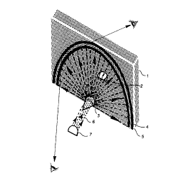
Figure 1 depicts one embodiment of the fountain in
which the rainbow is created through a diaphanous wall 1 of
water droplets. A radial pattern of illumination 2 is
projected by reflector cone 3 to create a primary and
secondary rainbow 4. The water droplet source is a series
of water nozzles 5.
The nozzles may be arranged in rows or series of
rows. The water spray from the nozzles may be adjusted by
spigots or the nozzle spray pattern may be preset. The
reflector cone 3 is positioned at the bottom center of the
fountain and illuminates the curtain of water droplets with
a fan of light. The reflector cone is a half-cone element
with a mirror-like finish with a half-angle of 45 degrees.
As shown in Figure 2, collimated light 6 from a searchlight
7 is directed to the cone 3. The path from the searchlight
7 to cone 3 may be covered with cover 9 to provide clear
light path through the spray and to protect viewers from
blinding light. In the Figure 1 embodiment, the center of
the radial light pattern 6 is located in the lower center
of the curtain of water droplets. However, positioning the
pattern at other locations will also produce adequate
rainbows.
The water droplets are uniformly distributed
across the light pattern and are relatively uniform in
size. Fine water particle spray nozzles in fluid
communication with a hydraulic source are used to create
W091/052~ ~e6~ - 10 - PCT/USgO/~540
the fountain. The water employed in the water particle
spray nozzles can be obtained from a water service, pond,
lake, river, sea, or water reservoir. A pumping unit which
provides proper water pressure can be arranged so that a
high percentage of the water can be recycled. Flow rate
and droplet size may be varied to modify the brightness and
appearance of the rainbows. A white light source is used
to create rainbows from the curtain. However, a
monochromatic light source such as a laser may be used to
create a single color bow.
As shown in Figure 2, a uniform radial pattern 8
of illumination is projected from a searchlight source 7.
The searchlight projects uniform collimated light 6, which
is transformed into a uniform pattern of radial
illumination 8, by conical reflector 3 with a half angle of
about 45 degrees. The light source, 7, and a portion of
the cone 3, have a cover, which prevents stray light from
being seen by viewers of the rainbow and the spray from the
fountain from interfering with the collimated light 6.
Figure 3 shows another arrangement of the light
source for providing the uniform radial pattern of
illumination. In this arrangement, two reflector cones as
shown in Figure 2 are positioned in tandem. This is
accomplished by having the bases lO of the two cones face
one another.
Figure 4 depicts an alternative method of
providing a uniform radial pattern of illumination. Light
WO91/05204 ~ 2 0 6 9 ~ Q 8 PCT/US90/054~
source 11 are embedded in an arc of 180~ so that the light
rays 12 emanate as from a common center 13 and also provide
a uniform distribution of light 14.
Figure 5 depicts an alternative method of
providing a uniform radial pattern of illumination in which
the reflector illustrated in Figures 3 and the arc array
15 illustrated in Figure 4 are combined.
Figure 6 depicts an alternative method of
providing a uniform radial pattern of iJlumination in which
two composite source such as shown in Figure 5 are combined.
Another alternative is shown in Figures 7 and 8.
In Figure 8, a uniform radial pattern of illumination is
created through an arc opening 20 in opaque cover 14.
Light source 15 emits a uniform distribution of light rays
16. As shown in Figure 7, the rays appear to emanate from
a common center 17 because they are reflected by reflector
19. Light sources 15 and the reflected light from
reflector 19 project a single radial pattern through
opening 20 in opaque cover 14.
It will be understood by those skilled in the art
that the present disclosure is not intended to limit the
invention to those embodiments described. On the contrary,
it is intended to cover all alternatives, modifications and
equivalents as may be included within the spirit and scope
of this invention.
The invention will be limited to solely by the
claims.