Language selection

Search

Patent 2069121 Summary

Third-party information liability

Some of the information on this Web page has been provided by external sources. The Government of Canada is not responsible for the accuracy, reliability or currency of the information supplied by external sources. Users wishing to rely upon this information should consult directly with the source of the information. Content provided by external sources is not subject to official languages, privacy and accessibility requirements.

Claims and Abstract availability

Any discrepancies in the text and image of the Claims and Abstract are due to differing posting times. Text of the Claims and Abstract are posted:

  • At the time the application is open to public inspection;
  • At the time of issue of the patent (grant).
(12) Patent Application: (11) CA 2069121
(54) English Title: URN LOWERING DEVICE
(54) French Title: DISPOSITIF D'ABAISSEMENT D'URNE
Status: Deemed Abandoned and Beyond the Period of Reinstatement - Pending Response to Notice of Disregarded Communication
Bibliographic Data
Abstracts

English Abstract


-7-
ABSTRACT
An urn lowering device includes a flat platform with a non-slip pad on the
top surface to support an urn. Two loops of cord are fastened at their ends to the platform
and pass through a handle ring above the platform so that the platform may be suspended
in a horizontal orientation from the ring. A second, retaining ring, surrounds the cords
above the urn and may slide down the cords towards the urn to further assist in retaining
the urn on the platform. Feet on the bottom of the platform support the platform in a level
position when it is lowered into a grave.


Claims

Note: Claims are shown in the official language in which they were submitted.

-5-
CLAIMS
1. An urn lowering device comprising a substantially flat platform with a top
face having an urn supporting area thereon, means providing a non-slip surface on at least
a part of the urn support area of the top face of the platform a plurality of suspension
means secured to the platform at positions spaced around the urn supporting area, handle
means engaged with the suspension means for supporting the suspension means with the
platform in a substantially horizontal, suspended position.
2. A device according to Claim 1 wherein the suspension means comprise a
plurality of loops of flaccid material, each with opposite ends secured to the platform.
3. A device according to Claim 2 wherein the handle means comprise a
substantially rigid member having aperture means therethrough through which the loops are
slideably engaged.
4. A device according to Claim 3 when the suspension means further comprise
retaining slide means engaged slideably with the suspension means for gathering the
suspension means together between the handle means and the platform.
5. A device according to any one of Claims 1 through 4 including a plurality of
feet projecting from a bottom face of the platform at spaced positions thereon.
6. An urn lowering device comprising a platform with top and bottom surfaces,
a non-slip pad on the top surface, two lengths of cord, each having two ends secured to the
platform, the cord ends being secured to the platform at positions spaced around the non-
slip pad, a handle ring, each of the lengths of cord passing slideably through the handle
ring, a retaining ring with each of the lengths of cord extending from the platform, through
the retaining ring, through the handle ring, once more through the retaining ring and to the
platform, and a plurality of feet projecting from the bottom surface of the platform.

-6-
7. A device according to Claim 6 wherein each cord has each end thereof
extending through a respective hole in the platform and secured to a respective one of the
feet.

Description

Note: Descriptions are shown in the official language in which they were submitted.


20G91 21
URN LOWERING DEVICE
The present invention relates to an urn lowering device, that is a device for
use in lowering an urn containing cremated remains ("cremains") into a grave.
In the interment of an urn, lowering the urn into the grave is cornmonly a
part of the graveside service. The grave is usually in the order of two to three feet deep,
so that manual placement of the urn in the grave is not a particularly dignified process. It
would therefore be desirable to be able to lower the urn in some other way into position for
burial.
The present invention aims at the provision of a device that enables the
dignified placement of an urn in a grave, ready for burial.
According to the present invention there is provided an urn lowering device
comprising a substantially flat platform with a Lop face having an urn supporting area
thereon, means providing a non-slip surface on at least a part of the urn support area of the
top face of the platform, a plurality of suspension means secured to the platform at
positions spaced around the urn supporting area, handle means engaged with the suspension
means for supporting the suspension means with the platform in a substantially horizontal,
suspended position.
In preferred embodiments of the invention, the platform is a rectangular,
transparent, acrylic plastic sheet. A non-slip pad of roughly the dimensions of the urn is
secured to the top surface of the sheet. Two cords are fastened to the platform, each
having its ends passing through the platform on opposite sides to form two loops of cord
above the platform. The cords pass siideably through a handle ring so that on lifting the
ring, the platform may be raised in a horizontal orientation. The um is retained on the
platform by the non-slip pad and by a retaining ring around the cord loops that may be
. .. , ;- - .- ,.

20~2~
slipped down the loops to gather the cord at the top of the urn. The retaining ring is
preferably a stiff rubber O-ring that will not slip readily ~,vhen the cords are tensioned.
The preferred embodiment also includes legs on the bottom side of the
platform, preierably at the ends of the cords. The legs provide stability to the platform
when plac~ in the grave so that the platform will rest level.
The device is intended to be constructed of inexpensive materials so that it
may be considered disposable. Consequently, the urn, when placed, need not be disturbed
to retrieve the lowering device.
In the accompanying drawings, which illustrate an exemplary embodiment
of the present invention:
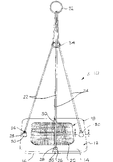
Figure 1 is a perspective view of an urn lowering device;
Figure 2 is a section along line 2-2 of Figure 1; and
Figure 3 is perspective view of the device shown supporting an urn ready
for lowering.
Re~erring to the accompanying drawings, there is illustrated an urn lowering
device 1~ that includes a flat platform 12 with a flat top surface 14 and flat bottom surface
16. The platform is made from a transparent acrylic plastic material. At the center of the
top surface is an urn support area generally designated 18 and covered by a non-slip pad
20. The pad is a sheet of resilient elastomeric material with a waffle-shaped configuration.
Materials of this sort are commercially available.
In use, the platform is suspended using two cords 22 and 24. The cord 22
has two ends 26 passing through respective holes 28 through the platform adjacent the mid
points of two opposite sides of the platform. Each cord end is fastened ~o a bell-shaped leg
which is in turn fastened to the bottom side of the platform. The cord 24 has its ends
., ~ ~ .; - ;
.... .... .. . . .. . ..

2~g912~
likewise fastened to legs 30 midway along the two remaining sides of the rectangular
platform.
Each of the cords 22 and 24 passes through a handle ring 32. Consequently,
when the platform is in a horizontal position and the ring is liftect, the cords will slide
through the ring to ensure that the platform will be lifted in a horizontal orientation.
To retain an urn on the platform, a retaining ring 34 surrounds the cords 22
and 24 be~ween the handle ring 32 and the platform 12. l'hus, each cord passes from the
platform, through the retaining ring 34, through the handle 32 and then back through the
retaining ring to the platform.
As illustrated mvst particularly in Figure 3, when an urn is placed on the
center of the platform, the retainer ring may be slid down to adjacent the top of the urn to
gather the cords 22 and 24 against the sides of the urn so that the cords, in co-operation
with the non-slip pad will hold the urn on the platform.
The present device is very simple and aesthetically pleasing. The non-slip
pad on the surface of the platform ensures that the urn will not move during the transfer of
the urn from position to position.
While one embodiment of the invention has been described in the foregoing,
it is to be understood that other embodiments are possible and will be manufacturecl
according to particular needs at any given time. Thus, the size and shape of the platform
may be varied to accommodate different sizes and shapes of urns. The cords are long
enough to ease the lowering of the entire platform and urn into graves of various depths.
However, the cord length can be altered to suit a particular need.
The entire device may be manufactured of relatively inexpensive material so
that it may be considered disposable and left in the grave with the urn. This means the urn
- . . , . ; : , . . .,,.: ; ,............ : . . . .
, .. , . .. ; . , . , - ... ; . . . :, . " .

2~691~1
need not be disturbed after placement. -~
It is to be understood that the present invention is not to be construed as
limited to the foregoing embodiments. The scope of the present invention is to be
ascertained slvwly by reference to the accompanying claims.
.. . . .
: .. .,: ~ .~; : . :

Representative Drawing
A single figure which represents the drawing illustrating the invention.
Administrative Status

2024-08-01:As part of the Next Generation Patents (NGP) transition, the Canadian Patents Database (CPD) now contains a more detailed Event History, which replicates the Event Log of our new back-office solution.

Please note that "Inactive:" events refers to events no longer in use in our new back-office solution.

For a clearer understanding of the status of the application/patent presented on this page, the site Disclaimer , as well as the definitions for Patent , Event History , Maintenance Fee  and Payment History  should be consulted.

Event History

Description Date
Time Limit for Reversal Expired 1997-05-21
Application Not Reinstated by Deadline 1997-05-21
Deemed Abandoned - Failure to Respond to Maintenance Fee Notice 1996-05-21
Application Published (Open to Public Inspection) 1993-11-22

Abandonment History

Abandonment Date Reason Reinstatement Date
1996-05-21
Owners on Record

Note: Records showing the ownership history in alphabetical order.

Current Owners on Record
DAVID P. GRAMBO
Past Owners on Record
None
Past Owners that do not appear in the "Owners on Record" listing will appear in other documentation within the application.
Documents

To view selected files, please enter reCAPTCHA code :


To view images, click a link in the Document Description column. To download the documents, select one or more checkboxes in the first column and then click the "Download Selected in PDF format (Zip Archive)" or the "Download Selected as Single PDF" button.

List of published and non-published patent-specific documents on the CPD .

If you have any difficulty accessing content, you can call the Client Service Centre at 1-866-997-1936 or send them an e-mail at CIPO Client Service Centre.


Document
Description 
Date
(yyyy-mm-dd) 
Number of pages   Size of Image (KB) 
Abstract 1993-11-21 1 18
Drawings 1993-11-21 3 73
Claims 1993-11-21 2 57
Descriptions 1993-11-21 4 144
Representative drawing 1999-03-08 1 24
Fees 1995-05-18 1 34
Fees 1994-05-19 1 29