Note: Descriptions are shown in the official language in which they were submitted.
~, METHODOFDEVELOP~NG . 2 0 6 9 1 8 9
- COMPLEX TOOL SHAPES
BACKGROUND OF THE INVENTION
1. Field of lhe Invention
The present invention relates generally to a method of developing the contours of
forming lools for m~tal members exhibiting complex shapes and, more particularly,
to such a melhod which utilizes the principles of age forming for forming the
member being fabricated. The techniques of the present invention represcnt an
improvement over those disclosed by H. Brewer and M. -
Holman in commonly assigned U.S. Patent No. 5,168,169,
entitled "Method of Tool Development".
Ir,
2. Descriptioll of tl~e I'rior Art
The complex shapes of Ille contoured members that make up aerospace structures
are inllerently difficult to form. Due to the shapes required by aerodynamics ~nd
20 beca-lse of the emphasis on load carrying capability combined with weight efficiency,
optimized dcsigns are created that require complex contours to be produced in high
strellgtll metals. Examples of such contoured members would include wing skin
paTlels, f-lselagc panels, and structural stiffening elements such as spars and
stri]lgcrs for aircraft applicatiolls; as well as the shroud, skirt, and tankagc members
~s of sp;lce launcll vchicles. Sucll members are characterized by extreme metal
thickness varialions alld integrally machined features. The criticality of design
requires precise forming tolcrances be maintained without sacrificing the fatigue
life, reliability, or strength of the member as a result of the forming process chosen.
3(J Convcnlional forming methods, such as roll forming, brake forming, stretch
forming, an(l p~ening, ~re cold working processes that achieve permanent
dcformatiolls througll the application of mechanic~l bending and/or stretching.
,~\chicving uniform forming across integrally machined features or abrupt changes
in thickness may not be possible without specialized tooling or extensive
' '~rA
, ~
2 20~91~9
,, .
modific~tions to the forming equipment. In some cases, it may not be possible todevelop the deformation forces necessary to accommodate extreme material
thicknesses.
While various machines can handle a wide range of metal thicknesses, it is not
- practical to form metals varying fron~one extreme of the thickness range to the
other, since most machines must be set up prior to operating. From this standpoint,
skin tapers and recesses that occur within a panel may not be formable. rO~ g
applications that have openings or cutouts machined into them may not be
10 formable without distorting the opening or leaving flat spots in the contour. Other
processes arc limited by the size of the forming machinery and those applications
that will fi~ within the working envelope. Custom equipment for larger or smaller
applications can be prohibitively costly and inflexible.
1~ In addition to the physical limitations imposed by part geometry are characteristic
traits that result from the forming process used. Traits such as strain hardening,
residual stresses, and marking accompany many of the forming processes
commonly employed. In some cases these effects can produce desirable qualities,
such as stress corrosion cracking resistance. Likewise others can produce
20 undesirable qualities, such as a negative effect on the htigue life and reliability of
the formed part. The point to be made is that each forming process must be
carcfully matclled to the intended application.
All of the conventional forming processes mentioned have one important
25 disadvantage in common: each requires the e,(~ Lse of a skilled operator. With the
exception of some processes which have been automated to an extent, considerableoperator skill is rcquired to obtain tight tolerances; thelerore, process consistency is
low. Part to part variations in contour can result in engineering specified contour
rcwork being required on every unit produced. Contour variations that do not
30 rcquire post forming corrections can still cause fit-up problems at assembly.Cc-ntour varialiolls rrom part to p~rt create numerous manufacturing difficulties,
c.lch wilh coslly solulions.
2069189
,
In the recent past, a significant advancement of known techniques for forming
complex mcmbers while maintaining or even improving upon their inherent
strength characteristics has been devised. Known as age forming, it is a process that
offcrs many solutions to the problems encountcred when conventional cold
formin~ processes are applied to complex shaped contoured members. During age
- forming, a part is rcstrained to a precletermined tooling contour and precipitation
aged. Age forming is a ,~focess that utilizes the phenomenon of metallurgical stress
relaxation during precipitation heat treatment for the purpose of converting elastic
strain to a plastic state.
lU
The age forming process may be performed on any of the precipitation heat-
treatable, met~ls and m~tal alloys such as aluminum alloys in the 2xxx, 6xxx, 7xxx,
and 8xxx serics.
~c-r examplc, to date, thc age forming process of the invention has been successfully
employed on at least the following aluminum alloys:
2xxx Series: 2014
2024
~~ 2124
2214
2219
2419
2090
6xxx Series: 6013
6061
7xxx Series: 7075
3() 7150
7475
8xxx Series: 8090
~ 206~18 9
Age forming is performed according to standard heat
treatment cycles utilized in precipitation hardening of
alloys. The underlying principles of precipitation heat
treating are explained in ~Aluminum Properties and
Physical Metallurgy", Edited by John E. Hatch, American
Society for Metals, Metal Parks, Ohio, 1984, pp. 134-138
and 177-188. As a result, suitable applications require
the final condition of the formed components to be in an
artificially aged temper. Every end use of a structure
must be reviewed in light of the property changes that
occur as a result of artificial aging. In some cases,
the mechanical properties associated with an artificially
aged temper may not be suitable for an intended applica-
tion. As an example, aluminum alloy 2024 loses fracturetoughness as it is artificially aged from the T3 to the
T8 temper. This change presents a barrier to age forming
applications where fracture toughness is a key design
element, such as lower wing skins and fuselage panels for
aircraft. Material and/or design changes are required in
these cases to allow for the utilization of age forming.
In other cases, age forming allows the added benefit of
being able to produce contours in a strengthened temper,
without developing high-levels of residual stress within
the component. An example of this feature is provided
when aluminum alloy 7150 is age formed from the soft W
temper to the hardened T6 temper.
More recently, the conventional age forming process has
been modified and substantially improved through the use
of the autoclave. The autoclave is a computer controlled
pressure vessel, with the added benefit of being a
~, ,
_ ~ 2~6918 ~
4a
certifiable source for heat treating aluminum. Age
forming has traditionally been performed in a furnace,
where a mechanical means of constraining the part to the
predetermined forming shape is required. The autoclave
offers the advantage of using vacuum and internal
pressure to obtain the desired contour. Since pressure
acts uniformly about the surface of the part, integrally
machined features receive the same deformation force as
the rest of the panel. Another important advantage is
that the forming pressure is distributed about the entire
surface area of the part. Therefore, a small
differential pressure can equate to many tons of applied
force when acting over a large surface. Most
conventional processes concentrate the forming forces
over a small area, thereby restricting the total
available deformation force.
~B
2069189
-
The autoclave is computer controlled allowing high levels of process consistencyand accuracy. Computer control allows the process to be operator independent. A
separate computerized system closely monitors and records the pressure and
temperature witllin the autoclave providing traceability and process verification.
- 5 These two features inherently endo~rautoclave age forming with hi~h levels of
process consistency and accuracy. Each panel receives the same processing;
consequently, repeatability is ensured. It is this feature that makes the process
adjustable. The tooling contour is "fine tuned" until the desired results are
obtained.
I ()
Toolin~ for thc auloclavc is designed according to the springback anticipated for the
application. Springb~ck refers to the tendency for a member being formed to return
to some shape intermediate its original shape and that of the tool to which it is
subjected during heat treatment. This phenomenon will ~e discussed at length
belo~v. Forming tools are designed with removable contour boards and other
features that allow for rapid contour modifications. Unlike other forming processes,
age forming does not typically allow for multiple forming iterations to be ~.folmed
upon the same piece. Age forming is a heat treatment process; therefore, running a
part more than once could result in over aging the material. Until the tooling
contour is finalized, contour corrections must be performed by another forming
process. Once the fillal tool contour is reached, secondary corrective forming
processes are not necessary.
This inabilily lo repca~ the heat treatment process on a member bein~ fabricatedrec~uires that it be scrapped if it exllibits an incorrect final contour and the procedure
repeated with a new member. The cost of labor and materials for such necessarilyrepeated iterations of the process have led to the methods of the present invention.
3()
r 2 0 6 ~ 1 ~ 9
SUMMARY OF THE INVENTION
A method is disclosed for developing the contour of tools employed for forming
metal members exhibitin~, complex shapes. The members are precipitation, heat-
treat~ble, meta]s cr metal ~lloys which are autoclave age formed. The resultin~
member is formed to the desired contour and, simultaneously, is heat treated to
reduce resiclual stresses while improving its strength characteristics. The invention
is p~rticularly concerned with a new tooling contour prediction method which is
based upon the apylica t ion of a unified viscoplastic model simulating the age
forming process.
The method of the in~ention ass~lres proper results on the first occasion the tool is
used, thereb~ resulting in considerable savings of labor and material.
Another aspect of this invention is as follows:
A method of age forming a desired metal member
having a surface contour of complex shape from an
unformed member including the steps of
(a) overforming the unformed member in a forming
tool having a contour of smaller curvature than the
contour of the desired member;
(b) constraining the unformed member in the
overformed condition;
(c) applying a thermal aging cycle to the member;
(d) cooling the constrained member following the
thermal aging cycle;
(e) releasing the constrained member from the
condition imparted by step (b) and allowing it to spring
back to a dimensionally stable condition which defines
the desired member having a surface contour of complex
shape;
and predicting the surface contour of the forming
tool comprising the steps, prior to performing steps (a)
through (e), of:
~,
2 0 6 9 1 8 9
6a
(f) simulating mathematically the application of
steps ta) through (e) solely on a model representing the
shape of a memker having the material properties of the
desired metal member; and
(g) determining from step (f) the contour of
smaller curvature in step (a) enabling the desired metal
member to be proAtlce~ upon the completion of step (e).
(~)ther and furlher features, advantages, and benefits of the invention will become
app~rcnt in the following description t~ken in conjunction with the following
dra-vings. It is to be understood that the foregoing general description and thefollowing detailed ~iescription are exemplary and explanatory but are not to be
restrictivc of lhe in-~ention. The accompanying drawings which ~re incorporated in
and constit~lte a parl of this invention, illustrate one of the embodiments of the
invcnlioll, al-d, togetller with the description, serve to explain the principles of the
in~cnlion in general terms. Like numerals refer to like parts throughout the
disclosure.
~: A
- . .
7 2069189
BRIEF DESCRIPTION OF THE DRAWINGS
Fig. 1 is a diagrammatic side elevation view illustrative of stress distribution in a
constant thickness bar being subjected to pure ben~ g for ~u~oses of explanationof the invention;
Fig. 2 is a stress-strain graph illustrating the relationship l,el~ stress and strain in
the outermost layer of material of the bar of Fig. 1 during a cold mechanical ro.~nmg
process, depicting both the elastic range of the material and the deformation in the
0 material after it has been stressed beyond the yield strength of the material;
Fig. 3A illustrates a stress-strain graph, similar to Fig. 2, but indicating ~e result of
an age forming process pe.rol,l,ed within the elastic range of the material;
Fig. 3B is a stress-strain graph, similar to Fig. 2, but indicating the result of an age
forming process performed when initial loading e,ccee.ls the yield point of the
material;
Fig. 4 is a perspective view, exploded, illustrating tooling for autoclave a~e forming
20 a member such as the bar of Fig. 1;
Fig. 5 is a detail cross section view illustrating the items shown in Fig. 4 within an
autoclave;
~ s. 6A, 613, 6C are successive diagrammatic detail end elevation views, partially in
section, illustrating successive steps of the age forming method of the invention;
Fig. 7 is a basic flow chart of the simulation model of the invention;
Fig. 8 is a diagrammatic cross section view of a forming tool and unstressed part
thereon presented on Cartesian coor(lin~t~c;
' 8 206918~
Fig. 9 is a graph depicting the predicted stress distribution on the central cross section
of a member for a range of pressures to exhibit the slopes chara-tt ~istics of elastic
plastic resl,o,.se;
Fig. 10A diagrammatically re~,ese,~ts a tool refe~ ce plane;
Fig. lOB diagrammatically represents a desired metal member cut by a plurality of
parallel spaced apart planes E~ n~ 9~ to the tool ~ef~nce plane of Fig. IOA;
o Fig. 11 is a diagrammatic representation, in section, of a cross sectional element
resulting from the interface of one of the l~el~e~ r planes in Fig. 10B and the
desired metal member;
Fig. 11B is a diagrammatic representation of a plurality of segments resulting from
lS the cross sectional element of Fig. 11A;
Fig. 12 is a process flow chart presenting the method of the invention in more
specific terms;
20 Pig. 13 presents a graphic illustration of the method by which a smooth continuous
curve is achieved utilizing the present invention;
Fig. 14 is a delail pcrspcctive view of a part of a tool resulting from the method of
the present invention;
z5
Fig. 15 is a diagrammatic view of a flattened cross sectional element enabling its
measurement on Cartesian coordinates;
Fig. 16 is a diagrammatic representation depicting a conl~ar;so~ I,el~.eell the shape
30 of a simulated age formed member and the shape of a cross sectional element; and
Fig. 17 is a ~raph dcpicting, for a range of thicknesses of a member to be fo~ e~, the
relationship between the radius of curvature of a forming tool and the radius ofcurvature of the formed part.
9 2069189
.
DETAILED DESCRIPTION OF THE PR~ L~ EMBODIMENT
In order to gain a better understanding of the phenomena behind the age forming
process of the invention, it is well to separately consider and analyze the forming
~=- 5 mechanisms at work during the age forming ~rocess. This effort can begin by
analyzing mechanical forming versus age forming in terms of stress distribution
found within the cross section of a specimen undergoillg forming. Another tool
desirably utilized for analysis is a stress-strain curve representing the outside layer of
fibers of a specimen undergoing forming. Through the use of these tools, a clearer
10 piclure can be obtained as to how each forming method works to form a piece of
material.
Considering the stress distribution throughout a part 20, depicted fo~ simplicity in
Fi~. 1 as a constant thickness bar of rectangular cross section, allows a com~ar~on to
5 be drawn between different forming mechanisms. As a force F is applied to the
simply supported bar to cause it to assume a radius, stresses diagrammatically
indicated at 22 are distributed throughout the ~hirl~ness of the bar. A neutral surhce
24 experiences no stress due to pure bending while the outside fibers e,-~elie.l ~ the
greatest stress. A concave side 26 of the bar experiences co~ r~sive stresses while a
2U convex side 28 of the bar experiences tensile slresses. Accor~il.g to Hooke's Law,
stress is directly proportional to the strain that is experienced when it is within the
elastic range of the material. The l~ro~GIlionality constant is known as the modulus
of elasticity and is dependent upon material and temperature. The strain
experienced by the fibers across the thickness of a spe~irnen depends upon the
25 distance of a particular layer of fibers from the neutral surhce.
If the stress induced throughout the bar stays within the elastic range of the
material, the bar will return to its original flat configuration with no forming taking
place once it is released. Therefore, if the bar is to retain a contour and be ~~ ed
3U without the aid of thermal stress relaxation, a significant amount of fibers within
the material must be stressed beyond their yield point. The stress-strain curve 30 in
Fig. 2 can be used lo examine the action involved in forming. The case of ill-l,al li~lg
a radius to a nat bar shaped part is not strictly a tensile application; rather it is one of
' lO 2069189
bending. Therefore, in reality, the use of a stress-strain curve is only applicablc to a
single layer of material at a given distance from the neutral surface. Nevertheless, it
serves the purpose of illustrating the differences ~,elweel- cold mechanical forming
and age forming. For example, the stress-strain curve 30 in Fig. 2 illustrates cold
mechanical forming of the bar 20 of Fig. 1 sulJje~led to bending stresses.
Consider the outermost layer of material on what will become the collve,c side 28 of
the bar. Initially the bar is flat and in a stress free state. As the bar is reco,lfigured to
assume a radius, the fibers in the outside surhce layer are strained which induces
o stress. This is illustrated by a stress distribution line 32 (Fig. 1) and by the stress-
strain curve (Fig. 2) beginning at the origin. The linear portion of the curve, which
defines the modulus of elasticity, or Young's modulus, for the particular alloy of the
bar 20, continues until the stress level reaches the yield strength 36 of the material.
If the bar is released at any point prior to inducing a stress greater than the yield
strength 36, it will unload along this same line and return to a flat (i.e., strain free)
condition. C)nce a layer of material is stressed beyond its yield point, the
relationship between stress and strain is no longer directly ~ro~l Lional (i.e., it is no
longer linear). If at this point the bar is released, it will unload along a line 38 that
has the same slope as the linear portion 34 of the load curve 30 but will be offset
from the original load line 34 indicating a retained strain 40. The slope is equal to
thc modulus of elasticity as previously noted. The resulting retained strain 40,referred to as plastic strain, indicates that permanent deformation has taken place.
Age forming forms a structure by taking advantage of the stress relaxation
phenomena associated with artificial aging. The age forming concept is illustrated
by the stress-strain curves in Figs. 3A and 3B. Fig. 3A depicts a specimen initially
stressed below the material's yield strength and Fig. 3B depicts a specimen initially
stressed bcyond the material's yield strength. Again, consider the outside layer of
fibcrs on what will bccome the convex side of a formed member, such as convex
sidc 28 of thc bar 20 of Fig. 1. These fibers will experience tensile stresses. As the
member is strained as indicated by a line 42 (Fig. 3A), the stress level increases
proporlionally. The vertical distance ~a (Fig. 3A) re~resents the amount of stress
experienced by thc fibcrs of the member while the horizontal distance ~t re~resel.ts
the amount of strain experienced. Upon reaching a particular radius, the member is
.~
11 2069189
(J '
held at this constant strain level (as at point 44) and the artificial aging cyde is
applied. Due to the metallurgical stress relaxation resulting from the materials'
exposure to temperature, the stress level reduces even though the strain rem~incconstant. The amount of stress relaxation that occurs, as indicated at ~b, de~e,~s
upon the material and its related aging temperature as well as the initial level of
5- stress induced. The rate of stress relaxation is greatly enhanced by a higher initial
stress lcvel and by a higher aging l~ yelature. However, these hctors are limitell by
the temperature permitted by the selected aging cyde. Once the aging is co~-ylete~
the member is cooled and released from its col,skaillts. This allows the mpmb~r to
0 spring back and physically relax the rPmsinin~ induced stress. The vertical distance
~c (~ig. 3A) represents the amount of stress relaxed during spring back while the
horizontal dis~ance ~3 represents the change in strain. Since strain changes, the
shape of the specimen also changes. In this case the s~e~ en is held in conhct with
the smaller radius of a forming tool and, upon release and following spring back,
assumes a larger radius. An amount of strain E2 is retained by the member
indicating permanent deformation.
In Fig. 3A, the pr~ctice of age forming has been illustrated within the elastic range of
the matcrial. It is in this region that the distinction bel~,~eell age forming and cold
mechanical forming is most evident. However, the same principles apply within
the inelastic range (above yield) as depicted in Fig. 3B. The most notable di~ere.lce
bct-vecn agc fcrming a specimen stressed within the elastic range versus one
strcssed within the inelastic range is best viewed by considering the action along the
strain (horizontal) axis. In a specimen stressed to within the inelastic range, the
2~ retained strain F15 (Fig. 3B) is col--yosed of two co~ ,ol-e.~ts. A portion of the
retained strain ~12 results simply due to stressing the specimen beyond the yield
point of the material. In Fig. 3B, point xx represents the specimen initially
rcconfi~ured to the shape of the forming tool prior to exposure to the aging cycle. At
lhis point, the level of stress is beyond the yield strength of the material. The yield
3n slrength is illustr~ted on the stress-strain curve 42A by point yy. If the s~e.-imen
bcin~ formed were to be released at point xx, prior to exposure to the elevated
le~ ,erature of the aging cycle, some re~inell strain ~12 would be exhibited s;~yly
bccause a porlion of lhe material has yielded. This is unlike the specimen
illustrated in Fig. 3A in which lhe specimen would return to a flat unskained
' 12 2069189
~J .
condition if released prior to elevated tL.l.~e~ature exposure. The total retained
strain ~15 of Pig. 3B, therelore, is a combination of the retained strain Fl2 due to
yielding of the material and the retained strain El3 due to metallurgical stressrelaxation.
s
In either the elastic or inelastic range, a~e forrning allows per-m- anent defor-m- ation to
be achieved with lower levels of applied stress than cold mel~h~nical forming.
Because of the way that cold mechanical forming works, residual stress levels
within formed parts can be quite high. It is here that age forming l,res_.~ts
lU significant advantages. First, the applied stress level required for forming is lower;
and secondly, stress relaxation occurs during aging, lo~ril-g it even more while the
part is held at a constant strain. After release from the forming tool, the age formed
part relaxes the remaining induced stress, which is si~,-.ifiraTltly lower than it was at
the start of the aging cycle. The result is that the age formed part has the same
; permanent deformation as the mechanically fo~ c~ part, but with much lower le~els of residual stress.
The amount of stress relaxation experienced by a member during forrning becomes
the key to determining the amount of springback the member will e~-~c.icnce
following age forming. Predicting springback is the fundamental requile.~ t to
taking advantage of the age forming method. Knowledge of springback is needed toaccurately determine forming tool contours.
For a brief initial explanation of the autoclave age forming ~rocess utilized for
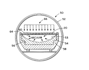
purposes of the invention, turn now to Figs. 4 and 5. An autoclave 50 (Fig. 5)
includes a generally thick-walled cylindrical vessel 52 which may typically be capable
of withstanding pressures up to 200 psi, total vacuum, and temperatures up to
' 600~F. With this apparatus, as diagla,lul-atically seen in Fig. 6, the part 20 is forced
from an initial unformed condition tPig. 6A) into intimate contact with the
contoured surface 53 of a concave die 54 (Fig. 6B) receivable in a cavity 56 of an
autoclave forming tool 58. This is ac.~ll.ylished by CO~.~.illg the top of the part 20,
die 54, and forllli,-g tool cavity 56 with a temperal.lre resista,.t vacuum blanket 60,
sealing the edges of the blanket, drawing a v~ m through a plurality of vacuum
ports 62 (Fig. 4) on the tool cavity bene~th the part, and, if desired, also a~ il.g
13 2069189
pressure to the upper surface of the part. A sealing frame 64 is removably mounted
on the forming tool 58 to maintain the positioning of the vacuum blanket 60. Thevacuum pulled underneath the part ensures that trapped air will not l~rev~.,t itfrom obtaining total contact with the forming tool. The forming tool contour is
5 designed to ove1fo,1n the part, allowing for springback. As noted above, pressure
~- may be optionally applied to the part ~s indicated by allo~s 66 to assure firm and
continuous coe~l,sive engagement of the die 54 by the part 20.
Up to this point, temperature has not been applied to the part, so that unless the
IU bending stress applied has exceeded the yield point of the material, no perm~ner.t
deformation has been achieved and the part is still within the elastic range of the
stress strain diagr~m. This condition provides the most si~nifi~nt feature of age
forming, sincc it can be ~1ro111.ed at lower applied stress levels than co11ve1ltional
forming techniques. If the part were released from the vacuum and pressure
holding it to the tool, it would essentially spring baclc to its initial flat condition (Fig.-
6A). However, with the application of heat at a~rol,-iate te1l1~e1atures for
appropriate periods of time, the part will, after the fG.1ni1~g ~rocess and after its
release from the tool, spring back to an intennediate position as indicated in Pig. 6C
The foregoing presents an early construction of an autoclave tool suitable for the
l,.ocess of the invention. However, it is not all indusive. More recently, tools have
been constructed with a skeleton framework of contoured boards co~,ered by a
contoured aluminum skin or caul plate. The l,ressure differential is created
between the top of the panel and the caul sheet. The co.1~our boards are not ~osed
2s to the pressure differe.-lial, except for those forces transmitted through the caul. A
sealing frame is nc longcr employed to seal the vacuum bag to the tool. Instead, the
vacuum seal is now maintained by adhesively attaching the bag to the surhce of the
caul with a tcmperaturc resistant putty. The newer tooling is simple, light-weight,
and less costly to build. Nor does the tooling have to be concave; it can just as easily
bc convex. Also, production tools are not generally cylindrical, although individual
contours arc constructed of circular segments. While vacuum and ~ressu1e are
,~re~erably cmployed to obtain the a~l,n,l,.,ate applied strain, purely mechanical
expedients, such as matched dies or clamps, may also be used. Much of the tooling
is simply a function of the desire to use a l,ress~lr~ differential for forming. Age
2069 18 9
1~
14
forming itself can be employed in both autoclaves and
furnaces using both pressure and mechanical means. The
method for developing the forming tool contour is the
same, regardless of whether a pressurized autoclave tool
or a mechanically clamped furnace tool is designed.
Springback is calculated as a function of the material,
its thickness, and the final contour desired only.
Regardless of whether age forming is performed in a
furnace or autoclave, the material's response to aging
remains the same.
Until the advent of the present invention, springback was
defined as the difference between the chord height of the
tool and the chord height of the formed specimen.
However, it was found that this method was very
restrictive and limited to predicting the springback of a
constant thickness bar specimen formed to a radius. The
old method was based purely on the percent change in
chord height. The stress-strain curve was not used.
This method was improved by using the stress relaxation
curve and strain retention curve prediction method as
indicated in U. S. Patent No. 5,168,169 recited above.
However, the improved method, just noted, is based on
experimental observations and was limited to the range of
test data that was used.
A new springback prediction method which forms the basis
of the present invention is based upon the application of
a unified viscoplastic model to simulate the age forming
process, providing a much more complete analytical device
than previously available to the tool designer. The age
forming method can be broken down into its various
~2 '
~. 2069 18 9
-
14a
stages: loading, stress relaxation, and springback. A
basic flow chart depicting this method is presented in
Fig. 7. In the present method, equations representing
the condition model are used to more fully describe what
is physically and metallurgically happening to the
material being formed. These equations attempt to
describe the laws governing the physical nature of the
material and changes taking place during the age forming
process.
They represent physical phenomena such as: elastic
strain, inelastic strain, stress relaxation, creep, and
the like, and the history of time dependent load
application and temperature exposure. Unique constants
are required to accurately represent
2069189
specific materials. The constants are determined by manipulating the constitutive
equations until they represent the age forming ~"ocess physically observed in test
spcclmens.
- 5 Once determined, the constants in conjunction with the constitutive model fully
rcpresent the material at hand as it undergoes the age forming l"ocess.
Theoretically, any model geometry can then be analyzed to determine nee~le~l a~eforming tool contours. More properly, this method is a modelling and simulation
technique rathcr than a prediction technique.
Mathematical modelling and simulation of age forming is flexible and inco.~orates
material properties and part geometry in an appropriate format. The model uses
this information to obtain the desired contour of a specimen being formed and topredict the residual stress in that spe~imen~ Integrating materials, as reylesented by
the constitutive model, and geometry into the model for the forming method
allows it to be adaptable to different combinations of part configuration and metal
alloy.
The benefits of a mathematical modelling and simulation of the a~e forming
method relate to the ability to know the degree of deformation required to
compensate for material springback and the characteristic forming tendencies
associated with a specific part configuration. The main benefit would be to
analytically determine the forming parameters thereby eliminating the need for
developing coslly and lime consuming empirical data.
The procedure to obtain the basis for the present invention will be divided into the
following seclions:
~NTRODUCTION
In autoclave agc forming, a melal part is heated to a temperature sufficient for it to
exhibit crccp and slress relaxation. It is then subjected to pressure which forces it
against a tool or mold. Creep may facilitate Ihis ~r~cess. Once it contacts the tool,
CA 02069l89 l997-l2-04
16
the part is held in place by the pressure for a period of time to allow stress relaxation
to relieve the stresses produced by forming. Finally the part is released and it5 partially springs back to a shape somewhere between its original shape and the tool
shape.
From the above description, it can be seen that the process is quite complex. A
variety of mechanical phenomena including elastic deformation, plastic deformation,
10 creep, and stress relaxation are potentially involved. This complexity of mechanical
response makes the use of a unified model of elastic and inelastic behavior
attractive.
CONSTITUTIVE MODEL
A mechanical model capable of a unified description of yielding, creep, and stress
relaxation is needed. The constitutive model also should have structure involving
evolution equations for measures of inelastic strain and a set of internal variables.
Microscopic concepts can be used in determining the forms of the equations
20 governing the evolution of the internal variables. The evolutionary nature of the
method of the invention allows a smooth transition from elastic to inelastic behavior
and thus eliminates the need for the explicit inclusion of a yield criterion. After
investigating several rossibilities, the Miller and Sherby constitutive model (see
Miller, A.K., and Sherby, O.D., "A Simplified Phenomenological Model for Non-
25 Elastic Deformation: Prediction of Pure Aluminum Behavior and Incorporation ofSolute Strengthening Effects," Acta Metallur~ica, Vol. 26, 1978, pp. 289-304) was
finally selected. The chosen model is potentially well suited for the simulation of a
complicated process such as age forming in which the relative contributions of such
phenomena as yielding, creep, and stress relaxation are initially unknown. In a
30 beam model, only the one dimensional forms of the Miller and Sherby equations are
needed. These are in a form and notation somewhat different from that used in
Miller and Sherby, for convenience, but not substantially different:
~ + (~ / z )(sinh(cr2 / E2f )))n E (1)
2069 ~8 9
17
f=(~)((sinh(~2/(E2O)n(sinh(~2fl)n) (2)
f(~)=fo (3)
where a superposed dot indicates differentiation with
respect to time (t).
The symbols ~, ~, and f represent, respectively, stress,
total strain, and an internal variable which is a
dimensionless form of the quantity called the drag stress
in Miller and Sherby. In these formulae and in the other
formulae set out hereinafter, the symbol h represents
thickness. The inclusion of the internal variable f
provides a mechanism for roughly modelling the internal
structural changes responsible for inelastic behavior.
The quantities ~, ~, fO and n are material constants while
E and ~ are temperature dependent material properties.
The physical interpretations of ~, ~, fO, and n are
discussed by Miller and Sherby. The quantity E is the
familiar Young's modulus of elasticity, and the quantity
T iS a relaxation time.
In order to utilize the Miller and Sherby model to
simulate the behavior of a specific material, a set of
material constants appropriate for that material must be
determined. In the present work this was done with
reference to uniaxial constant strain rate tension tests,
uniaxial constant stress creep tests, and uniaxial
constant strain stress relaxation tests which are
conducted for the desired alloy.
B
E~ 206918 9
-
17a
All the tests mentioned above involve uniaxial loading
under quasistatic conditions. For the circumstances, the
quantities~~, ~, and f can be regarded as constant
throughout the specimen. The equations (1) and (2) are a
set of two simultaneous differential equations which can
be solved to determine either ~(t) and f(t) when ~(t) is
given (as in the tension and stress relaxation tests) or
~(t) and f(t) when ~(t) is given (as in the creep tests).
The problem of carrying out the solution of equations (1)
and (2) numerically is complicated by the numerical
stiffness of the system.
In the present work it was decided to employ the Euler
two point forward difference method and to deal with
numerical stiffness by using a very small constant step
size. The procedure was verified by reproducing several
simulations reported by Miller
'Q
18 2QS9189
and Sllcrby for pure aluminum using the material constants given in the first
column of Table 1.
Table 1. Material Constants
Pure Aluminum 7075 Aluminum Alloy
a 4.70 x 10⁷ 5.00 x 10³
5.50 x 10³ 3.75 x 1o2
n 4.70 5.00
f" 3.30 x 10⁻⁹ 3.00 x 10⁻⁹
2.97 x 1ol4 sec 6.06 x 10⁷ sec
E 6.96 x 10⁷ kpa 6.55 x 10⁷ kpa
.
l;
It ~as found that any sudden application of stress or strain produced numerical
difficulties. Thus creep tests were simulated by increasing the stress to its final
constant value over a time which was small compared to the duration of the test
and stress relaxation tests were simulated by increasing the strain to its finalzo constant value over a time that was small compared to the duration of the test.
Because of the complicated structure of equations (1) and (2), it is impossible to
iden~i~y each of thc material coefficients with a unique aspect of the material and
rcsponse. Thus, the dctermination of the coefficients involves a trial and error25 process based on a large number of simulations. In the present work a ~l~cedure
similar to that described by Miller and Sherby was used to obtain initial estimates of
the constants. This procedure is based on data from uniaxial creep tests and uniaxial
tension tests. These estimates were then refined using the available data for
uniaxial stress relaxation tests. For example, the values ultimately selected as~n appropriatc for agc forming simulations of 7075 aluminum alloy are given in the
sccond column of Table 1.
BEAM MODEL
23S9189
19
A part could be reprcscntcd by a simply supported beam subjected to uniform
pressure. It is assumed that the contact between the tool and the part is established
everywhere simultaneously and that the contact pressure can be treated as uniform.
It should be noted that, consistent with the above discussion, during the contact
- phase the pressure appearing in the subsequent equations represents the difference
bctween thc applied pressure and the contact pressure. The beam model will first be
dcveloped in a form suitable for the solution of any bending problem and then
specialized to the age forming problem.
To develop the appropriate equations for quasistatic bending let the x,y plane be the
plane of bending with the x axis being horizontal and the y axis vertically upward
(sce l~ig. 8). The undeformed neutral axis corresponds to y=O. The cross section of
the beam is characterized by an ~rea A and a moment of inertia about the neutralaxis
I = y2dA
1 ~ A (4)
The bending moment is defined to be
M(x,t) = - ~ydA
~5 ' ' ~ (5)
The verlical displacement of the neutral surface is v(x,t).
~n thc be~m modcl thc stresses and strains can vary with x and y as well as t. Thus,
thc supcrposcd do~s appcaring in equations (I) and (2) must be replaced by partial
dcrivatives with respect to t. Doing this and substituting the geometric relationship
e = -y/R(x,t) = -ylc(x,t) (6)
206!~189
-
(R being the radius of culvature of the neutral surface and ~ being its curvature, that
is, I/R) into equations (1) and (2) yields
~+(Ek)(sinh(~2/(E2f)))n=-Eyat~ (7)
-- atf=(a/~)((sinh(~2/(E2f)))~(sinh(,B2f))n) (8)
Integrating the product of y with equation (7) over the cross section and using
equ~tions (4) and (5) yiclds the additional equation
,.
~M ~ ) (sinh(~ /(E2f~)) ydA=EI~
(9)
For small deflections, the relationship between curvature and displacernent is
IC = a2v (10)
20 For statically determinate problems, equations (7-10) are sufficient to define the
problem. For st~tically indeterminate problems, they must be supplemented by thequ~sistatic equilibrium equation
q = a,~M (11)
where q is the upward loading per unit length. It is to be obsel ved that for t = oo one
integration of equation (9) with respect to t produces the usual moment curvature
equ~tion for clastic bcing ~=M/(EI) and substituting this into one integration of
cqu~lion (7) wi~h respcc~ to t yields the usual elastic flexure stress distribution
~=-My/I.
The intcgral appearing in equation (9) illustrates the fact that, without further
assumptions, a beam (or plate or shell) theory cannot be rendered entirely
indcpendcnt of the thickness coordinate when a unified model of elastic~inelastic
CA 02069189 1997-12-04
response is employed . In the present situation this is because the variations of (J and f with
y are not given but must be determined as part of the solution.
The solution of equations (7-11) is a formidable problem. In the age forming experiments
being simulated it was found that the formed parts closely resembled circular arcs. It was
decided, therefore, to simplify the model by assuming that equation (10) could be replaced
with the appropri~te equation based on the geometry of a circular arc. Doing this allows
10 the solution to be carried out at each cross section independently. In the present work only
the central cross section, the location of the maximum stresses and displacements, was
considered.
The age forming model involves a statically determinate simply supported rectangular
15 beam (of length 1, width b, and thickness h) loaded by a uniform downward pressure p
(note: q=-pb). Thlls the central moment is
M=pbl2/8 ( 12)
20 and the moment of inertia is
I = bh3/12 (13)
Suppressing the dependence on x in equations (7-9) (since x is fixed at 1/2) and using
25 equations (12) and (13) one obtains
C~t~+(E/~)(Sinl~ 2 /(E2f)))n =_~y (14)
dtf =(~/~)((sinh(~r2/E2f)))n_(sinh~2f))n) (15)
2))1h/2(Sjnh(~J2 /(E2f )))nydy = 2rh3~l (3l2) (16)
CA 02069189 1997-12-04
Equations (14-16) are a set of dirrele"lial equations which can be used to determine (J(y,t)
and f(y,t) on the central cross section together with either lC(t) (if p(t) is given) or p(t) (if
S Ic(t) is given. The equation
V = R(~ (2R))2)l/2); R-
(see Fig. 8) is used to determine the central deflection.
Before ~llel.,pling to simulate the entire age forrning process, simulations are made of the
process of deforming a beam by a pressure which starts at zero and increases linearly with
time. The material properties for pure aluminum given previously are employed and the
dimensions are assumed to be l= 76.2cm (30 in.), b = 7.62cm (3 in.), h= 1.27 cm (O.Sin.).
The simulations are carried out as follows. In the upper half of the cross section, N points
are chosen and the quantities ~ l, and fj, I = 1,2,...,N are associated with these points.
The initial state is i~ssumed to be quiescent, that is
~ j =0, fj = fO; i=1,2,.. ,N. (18)
Since p(t) was known in this case, the governing equations were arranged in the form
((E / r)(sinh(~ j2 / (~2f )))n + 3l2p / (2h2 ))
-(24E/(~2))¦ (sinh(~2 /(E2f )))nydy)(ylh));i = 1,2,.. ,N (19)
fj = (~ / r)((sinh(~Jj2 / (E2fi )))n _ (sinh(~2f ))n); i 1 2 N (20)
23 2069189
-
~hR
K= (31 p/(2Eh2) - (24/(lh2)) (sinh(~2/~ ))n d )/h
'~ (21)
~nd these 2N+1 ordinary differential equations are integrated forward by the well
- ~ known Eulcr method to dctermine ~j(t~, fj(t), and IC(t). It is interesting to note that,
since the Euler method is being used, the integrals appearing in equations (19) and
(21) are always evaluatcd at the previous time. Thus, no iteration is required. This
may not be true for many, more complex, numerical methods.
o The capability of the present beam model is illustrated in Fig. 9 which shows the
predicted stress distributions on the central cross section. For the lowest three
pressures the stress distributions are linear which is characteristic of elastic response.
Beginning wi th the fourth pressure the stress profiles exhibit the slopes
characteristic of elastic plastic response. The yield stress is a~v~roximately 10 Mpa
lS which is consistent with data reported by Miller and Sherby. The yielded region is
seen to occupy an increasingly large portion of the cross section as the appliedpressure is incrcased. For the largest pressure shown, virtually the entire cross
section has yielded. It is felt that this simulation of the transition from elastic to
plastic behavior (yielding) is quite good.
AGE ~ORMING SIMULATIONS
The age forming process consists of three stages as discussed earlier. These will be
refcrred to herein as loading, stress relaxation, and springback.
Thc loading stage is simulated exactly a~ described at the end of the previous section.
It is terminated when the part is predicted to be in contact with the tool, that is,
when R=I/K jS found to be equal to the tool radius Rt.
3() To simulate the s(ress relaxation stage the curvature of the part is held constant at
thc (ool curvaturc (tl-us making K =0) and equations (19-21) are rearranged to read
~j = (E/~)(sinh(~2j/(Efi))); i = 1,2,.. ,N (22)
24 2Q&9189
-
(~/ )(( i h(~2j/~E2fi)))n - (sinh(~2fi))n); i = 1,2,...,N (23)
p (l6E~(Tl2)) (sinh(~ /(E2f~)) ydy
_ 5 "~ (24)
Equations (22) and (23) consist of N sets of two coupled equations. These are
integrated forward by the Euler method to determine c~j(t) and f'(t). Then equation
(24) is integrated forward by the Euler method to find p(t). The stress relaxation
o stage- is terminated after 24 hours.
It is to be recallcd that in the present idealized model the quantity p represents the
difference bet-veen the forming pressure and the distributed reaction between the
part and the tool. This quantity decreases as the stress relaxation stage proceeds. At
the end of the stress relaxation stage the forming pressure is removed. This relie~res
the contact between part and tool, thus causing the distributed reaction lJelwe~.l part
and tool to vanish. ~n the simulations, therefore, the springback stage is
characterized by reducing p to zero at a constant rate and then holding it there. The
simulations are carried out using equations (19-21) just as for the loading stage. It
20 has been found that cllanges in ~c virtually cease once p reaches zero (that is R=1/1c at
the end of the unloading sta~e is equal to the part radius, Rp). The corles~ol-ding
valuc of R=l/~ is used to characterize the amount of springback. It is also to be
recalled that in the actual experiments the part is cooled before the pressure is
removed. In the simulations, this cooling is accounted for by the appropriate
;~5 changes in E and I in the unloading stage.
Determining the proper amount of overform a metal member must be subjected to
during age rorming is critical to successfully forming the desired metal member.Thc more complcx the desired member, whether in contour or in thickness
variation, thc more complex the forming tool contour must be. The unified
viscoplastic model which has been described simulates the behavior of a metal item
when subjcc(cd (o age forming. Thererore, the model can become a key component
to an overall schcme for predicting an age forming tool's contour. The followingpresents three schemes for such predictions. In each scheme, a complex shaped
CA 02069189 1997-12-04
metal member of desired contour is analyzed and information from that analysis is used in
conjunction with the simulation model to produce a forming tool contour.
For example, consider a wing skin panel as the metal member requiring form. Thickness
varies throughout the panel as required by its intended purpose as a wing covering. Also
the shape to which it must conforrn is complex as defined by the airfoil shape. In order to
predict the require(l forming tool contour, the shape of the desired metal member must be
known. A scheme for analyzing the shape and thickness variations of the desired member
10 has been developed which simulates subjecting the member to a plurality of two-
dimensional cuts or slices. First, a geometrical representation of the desired member is
created in an electronic three-dimensional graphics package such as that sold under the
trademark "CATIA". Here the shape of the desired member can be fully described in
terms of an x, y, z coordinate system. Within this medium, a plane of reference is
15 established. This reference plane is labeled as the Tool Reference Plane (TRP) 201 (Fig.
lOA). This plane represents a desired or contoured metal member 203 in a flat condition
prior to forming. The desired metal member in its final configuration is illustrated in Flg.
1 OB. With TRP 201 established, conveniently spaced apart planes 205, 207, 209
perpendicular to the TRP 201 are used to cut or slice the desired metal member 203 can be
20 defined in a two-dimensional and cross sectional format as seen in Fig. 1 lA. Each scheme
for detenmining the rorming tool contour utilizes the resulting cross sectional elements 211.
Each cross section as represented by its associated cross sectional element 211 provides
infonmation concenling shape and thickness variation. For the first scheme of detenmining
25 the fonming tool contour, each cross sectional element is divided into segments 213, 215,
217, 219, respectively, containing substantially similar thickness (hl, h2, h3, h4 respectively)
and substantially similar radius (Rl, R2, R3, R4 respectively) combinations, each with a
corresponding length (Il, l2,l3, 14 respectively) as shown in Fig. 1 lB. Depending upon the
cross section, sevel al segments may come from a single cross sectional element. The next
30 step is to detenmine what forming tool radius would be required to produce the shape of the
segments described above.
y~
At this point the simulation model is used. The simulation model simulates age
forming as applied to a nat specimen being formed upon a specifically shaped tool.
The model accurately predicts the final shape of the s~e~ en having undergone
the age forming method. In order to fully utilize the simulation, it is necessary to
vary thc shapc of thc forming tool and compare the results of the predicted final
shape with the shape of the segment being sought. For each segment, the desired
radius sought in the segment, its length, and its thickness are supplied to the
simulation model. The model creates a member having a length and a thickness
equivalent to the segment being analyzed. An initial tool radius which is smaller
than the radius of thc segment being analyzed is supplied to the simulation model.
The model then simulates the age forming of the created member as if formed
against this initial tool radius. The final radius produced by the simulation is then
compared to the desired radius of the segment being analyzed. Predetermined
values are established in the simulation model as being acceptable differences
between simulated and desired values. If the differences between the desired andsimulated radii are not acceptable, then the simulated forming tool radius is
adjusted according to these differences. The simulation is ~elfo~med using the new
tool radius, and comparisons are made again. The scenario continues in an iterative
fashion until the differences between the simulated and desired radii are withinacceptable levels. Once the differences are acceptable, the forming tool radius
utilized by the simulation is outputed as the forming tool radius required to age
form a member of the specified thickness to the desired final radius. This
simulation is continued for each different thickness and radius combination
rcpresentcd by cach segment. A flow chart illustrating the use of the simulation~r~ modcl for thi~s .schcme is shown in Fig. 12.
Wi th lhis technique, a forming tool radius is produced for each segment. A
composilc forming tool contour for the entire cross-sectional element is then
dctcrmined ~y t~ngentially attaching the tool radii of adjoining segments in
~o rcspcctive ordcr, each having the length of the original segment. See Fig. 13. This
crcates lhe tool contour 220 needed to produce the cross-sectional element shape. To
dctermine the surface of the three-dimensional forming tool surface, each forming
tool curve is relocated in the plane for example, planes 205, 207, 209, from which the
CA 02069189 1997-12-04
original cross-secti"nal element came. Once all of the forming tool curves are in place, they
are smoothly conne ted by fairing in a finished surface 221 (Fig. 14) between them with the
5 aid of an electronic lhree-dimensional graphic system such as that known by the trademark
"CATIA". This finished surface 221 represents the definition of the forming tool contour.
A second scheme exists for determining forming tool contours utilizing the age forming
simulation model. Similar to the first scheme, again viewing Fig. 10B, the desired metal
member 203 is analyzed with conveniently spaced apart planes 205, 207, 209
perpendicular to the tool reference plane 201 (Fig. 10A). Once again these planes are
oriented across th~ contour and create cross sectional elements. Unlike the first scheme,
however, the entire cross sectional element 211 is considered at once by the computer
simulation. The element is first analyzed by considering its thickness profile. This can be
15 done by considering the cross sectional element as a series of segments as in Fig. 1 lB.
From this, a flat panel thickness profile 223 can be determined as seen in Fig. 15. This
allows the panel to be described by a coordinate system where the y-axis (ordinate)
represents thickness (hl, h2, h3, h4 respectively) and the x-axis (abscissa) represents
distance across the panel (ll, 12,13,1~ respectively). This information is provided to the
20 simulation model. Additionally, the shape of the cross sectional element 211 is described in
terms of an x-y coordinate system. Also, the initial forming tool contour is approximated a
having the same basic shape as the cross sectional element but containing similar radii of
curvature. The forming tool contour is also described in terms of an x--y coordinate
system. Both it and the cross sectional element coordinates are supplied to the simulation
25 model. The measurement of the x-y coordinates of each of these shapes is facilitated by the
use of the electronic graphics packaged noted above. Alternatively, the shape of the cross
sectional element and the shape of the forming tool contour could be described as a
mathematical expression and be supplied to the computer simulation in that form.
30 With the thickness profile and the shape description available, the computer simulation
model is ready to operate. The model creates a simulated metal member of uniform ~vidth
containing the thickness profile of the cross sectional element. The model simulates this
created member being age formed against the approximated forming tool shape. The
CA 02069189 1997-12-04
28
simulation concludes by describing the final shape of the created member after it
experiences spring back. The final shape of the created member is compared to the shape
of the cross sectional element. If the initial approximation of the forming tool shape is
5 correct, then no difference will be found between the shape of the simulated agé formed
member 225, represented by dash lines in Fig. 1-6, and the shape of the cross sectional
element 211, represented by solid lines in Fig. 16.
A comparison between these two shapes can be made by taking the vertical difference
10 between them at various x-coordinate locations (Al,~2,~3), also as shown in Fig. 16. Each
difference can be compared to a predetermined tolerance value to establish whether or not
the differences are acceptable. If the differences are not acceptable, then the simulated
forming tool shape is adjusted and the age forming simulation is performed again using the
same created member as before. The differences indicate the amount of underform or
15 overform that occurs in the simulated member as compared to the cross sectional element.
The simulated forming tool shape is adjusted by adding or subtracting the differences
measured between the simulated age formed member and the cross section element. For
instance, if the comparison indicates the simulated age formed member is underformed at a
particular x-location, then the simulated forming tool is redefined as having more deflection
at that particular location, the amount being equal to the difference between the simulated
member and the actual cross sectional element.
This iterative process continues until the differences measured are within the acceptable
tolerance level. The simulated forming tool contour used to produce the acceptable created
member shape is outputted from the simulation program in either an x-y coordinate format
or as a mathematical expression. This represents the tool contour needed to produce the
cross sectional element.
With this information for each cross sectional element, the three-dimensional tooling is
30 created in the same manner as described with respect to the first scheme.
A third scheme for determining forming tool contour is very similar to the first scheme in
the way it analyzes the complex shaped member to be formed.
CA 02069189 1997-12-04
29
Conveniently spaced planes are utilized and cross sectional elements are created. Segments
of each element are determined from sections having substantially similar radii and
5 substantially similar thicknesses, each with a corresponding length. The great difference
between the two schemes is in the manner in which the age forming simulation is utilized.
In the first scheme, the simulation model is used to determine unique forming tool radii for
each segment. In this scheme, the simulation model is used to prepare a general
relationship between forming tool radii and formed members. This method is attractive in
10 that simulations can be run for a given material prior to any knowledge of the shape of the
complex member requiring form. The relationship is developed by simulating the forming
of a range of thicknesses against a variety of forming tool radii where RT is tool radius, RP
is part radius, and h is part thickness. This relationship can be displayed graphically as
shown in Fig. 17. With this relationship, each segment can be analyzed according to its
15 thickness and final formed radius. The resulting tool radii can be used to create a
composite tool curve 227 for the entire cross sectional element similar to the first scheme
shown in Fig. 13. The forming tool curves can be located in their respective planes, then
faired together into a surface to define the complete forming tool surface.
20 While preferred embodiments of the invention have been disclosed in detail, it should be
understood by those skilled in the art that various other modifications may be made to the
illustrated embodiments without departing from the scope of the invention as described in
the specification and defined in the appended claims.