Note: Descriptions are shown in the official language in which they were submitted.
- 1 2069258
STRIP CASTING
TECHNICAL FIELD
This invention relates to the casting of metal
strip. It has particular but not exclusive application to
the casting of ferrous metal strip.
It is known to cast non-ferrous metal such as
aluminium by continuous casting in a twin roll caster. Hot
metal is introduced between a pair of contra-rotated
horizontal casting rollers which are cooled so that metal
shells solidify on the moving roller surfaces and are
brought together at the nip between them to produce a
solidified strip product at the outlet from the roller nip.
The hot metal may be introduced into the nip between the
rollers via a tundish and a metal delivery nozzle located
beneath the tundish so as to receive a flow of metal from
the tundish and to direct it into the nip between the
rollers.
Although twin roll casting has been applied with
some success to non-ferrous metals which solidify rapidly
on cooling, there have been problems in applying the
techn~ique to the casting of ferrous metals. One particular
problem has been the need to ensure a very even metal flow
- distribution across the width of the nip since even minor
flow fluctuations can cause defects when casting ferrous
metals. Previous proposals to achieve the necessary even
flow have involved the provision of baffles and filters in
the delivery nozzle outlet to reduce the kinetic energy of
the falling molten metal in such a way as to produce a
smooth even flow at the outlet. These proposals have met
with some success but have generally required the flow to
be constricted through a quite narrow outlet discharging
into a pool of accumulated molten metal in the nip between
the casting rollers. The present invention provides an
alternative technique for obtaining an appropriately smooth
even flow of molten metal. The technique enables easier
control of the flow process and also enables the use of
nozzles with wider slot outlets.
' - 2 - 2~69258
DISCLOSURE OF THE INVENTION
According to the invention there is provided a
method of casting metal strip of the kind in which molten
metal is introduced between a pair of parallel casting
rollers via a metal delivery nozzle disposed above the nip
between the rollers, wherein the delivery nozzle has an
upwardly opening inlet trough to receive molten metal and a
metal flow passage extending downwardly from the bottom of
the inlet trough to a metal flow outlet from the nozzle and
wherein molten metal is supplied to the delivery nozzle in
one or more free falling streams so as to impinge on a side
wall surface of the inlet trough of the nozzle at an acute
angle of impingement such that metal from the or each
stream adheres to the side wall surface to form a flowing
sheet of metal on the side wall surface which is directed
by the side wall surface into the outlet flow passage.
Preferably, said angle of impingement is in the
range 10~ to 50~.
Preferably, the molten metal is delivered to the
nozzle in one or more substantially vertically falling
streams and said side wall surface of the nozzle trough
slopes downwardly and across the trough to intercept the or
each stream at said acute angle of impingement and to
defle~t the flowing metal transversely of the vertical
direction.
Said side wall surface may be provided with a
pattern which promotes spreading of the molten metal
transversely of the direction of the or each stream. The
surface pattern may comprise a plurality of corrugations or
undulations extending transversely to the direction of the
or each falling stream.
Preferably, said wall surface curves downwardly
and inwardly of the trough so as to direct said sheet
flowing to the outlet passage with progressively increasing
slope away from the vertical.
Preferably further, the outlet passage is shaped
to direct metal flowing therethrough transversely of the
nozzle against the direction of transverse deflection of
the flow in the trough.
More particularly, the outlet passage may have an
- 3 ~ 5 ~
upper portion which extends transversely of the
nozzle against the transverse deflection of the flow
in the trough and a lower portion which extends
substantially vertically to the nozzle outlet.
Preferably further, said lower part of the
outlet passage has a discrete constriction spaced
above the nozzle outlet
The invention also provides a metal
delivery nozzle for delivery molten metal to a nip
between a pair of casting rollers, comprising an
upwardly opening inlet trough to receive a free
falling stream of molten metal and a metal flow
passage extending downwardly from the bottom of the
inlet trough to a metal flow outlet of the nozzle,
wherein the trough has a side wall surface which
slopes downwardly and across the trough to the metal
flow passage whereby, in use of the nozzle, a free
falling stream of molten metal can impinge on said
side wall surface at an acute angle of impingement
such that molten metal impinging on the side wall
surface will adhere to that wall surface and flow in
a sheet directed by the wall surface to the outlet
passage.
Preferably, the side wall surface has a
pattern which in use of the nozzle promotes
spreading of the molten metal transversely to the
direction of metal flow. More particularly, the
side wall surface may be for~med with a plurality of
corrugations or undulations extending along the
trough.
Therefore, in accordance with the present
invention, there is provided a method of casting
metal strip comprising introducing molten metal
between a pair of parallel casting rollers from a
metal delivery nozzle disposed above the nip between
the rollers wherein the delivery nozzle has an
- 3a -
upwardly opening inlet trough adapted to receive
molten metal, and a metal flow passage extending
downwardly from the bottom of the inlet trough to a
metal flow outlet from the nozzle and supplying
molten metal to the delivery nozzle in at least one
stream so as to impinge said molten metal on a side
wall surface of the inlet trough of the nozzle;
said wall surface being curved inwardly
and downwardly of said trough, and impinging said
molten metal on said curved wall surface at an acute
angle, with respect to the stream of molten metal,
of impingement, such that said stream adheres to the
side wall surface to form a flowing sheet of metal
on the side wall surface which is directed, at an
increasing slope away from the direction of
introduction of said molten metal, by the said wall
surface into the outlet flow passage.
Also in accordance with the present
invention, there is provided a metal delivery nozzle
for delivering molten metal to a nip between a pair
of casting rollers, comprising an upwardly opening
inlet trough adapted to receive at least one free
falling stream of molten metal and a metal flow
passage extending downwardly from the bottom of the
inlet trough to a metal flow outlet of the nozzle,
wherein the trough has a side wall surface which
curves downwardly and inwardly across the trough to
the metal flow passage whereby, in use of the
nozzle, said free flowing stream of molten metal
impinges on said side wall surface at an acute
angle, with respect to said falling stream of metal,
of impingement such that said molten metal impinging
on the side wall surface will adhere to that wall
surface and flow in a sheet, with a progressively
increasing slope away from the vertical, directed to
the outlet passage.
,
5 ~
- 3b -
Further in accordance with the present
invention, there is provided a method of casting
metal strip of the kind in which molten metal is
introduced between a pair of parallel casting
rollers via a metal delivery nozzle disposed above
the nip between the rollers, wherein the delivery
nozzle has an upwardly opening elongate inlet trough
extending longitudinally of the nip to receive
molten metal and a metal flow passage extending
downwardly from the bottom of the inlet trough to a
metal flow outlet from the nozzle, the nozzle inlet
trough has a side wall surface which slopes
downwardly and across the trough, and the molten
metal is delivered to the nozzle in a series of
discrete free falling vertical streams spaced apart
longitudinally of the trough and each impinging on
said side wall surface of the nozzle at an acute
angle of impingement in the range 10~ to 50~ whereby
molten metal from the streams adheres to the wide
wall surface and spreads into the form of a single
sheet of molten metal which flows down the side wall
surface into the outlet flow passage.
Still further in accordance with the
present invention, there is provided an apparatus
for casting metal strip comprising a pair of
parallel casting rollers forming a nip between them,
a metal delivery nozzle disposed above the nip
between the casting rollers for delivery of molten
metal into the nip and a tundish disposed above the
delivery nozzle for supply of molten metal to the
delivery nozzle, wherein the metal delivery nozzle
comprises an upwardly opening elongate inlet trough
extending longitudinally of the nip to receive
molten metal from the tundish and a metal flow
passage extending downwardly from the bottom inlet
trough to a metal flow outlet from the nozzle, the
- 3c - ~G~2~
nozzle inlet trough has a side wall surface which
slopes downwardly and across the trough, the tundish
has a series of flow outlets disposed in a linear
array extending longitudinally of the delivery
nozzle trough and directly above said side wall
surface of the trough such that in use of the
apparatus molten metal will fall freely under
gravity from the tundish nozzle outlets in a series
of discrete vertical streams to impinge on said side
wall surfaces of the nozzle at an acute angle of
impingement in the range 10~ to 50~.
BRIEF DESCRIPTION OF THE DRAWINGS
In order that the invention may be more
fully explained, one particular form of apparatus
and its operation will be described in some detail
with reference to the accompanying drawings in
which:
Figure 1 illustrates a continuous strip
caster incorporating apparatus constructed and
operating in accordance with the present invention;
Figure 2 is a vertical cross-section
through important components of the caster
illustrated in Figure 1 including a metal delivery
nozzle constructed in accordance with the invention;
Figure 3 is a further vertical cross-
section
through important components of the caster taken tran9sv2é~s8e
to the section of Figure 2;
~ Figure 4 is an enlarged transverse cross-section
through the metal delivery nozzle;
Figure 5 is a broken away perspective view of
part of the metal delivery nozzle illustrating how a series
of falling metal streams impinge on a sloping wall surface
of the nozzle and merge into a single sheet flow down that
wall surface;
Figure 6 is a transverse cross-section through a
modified form of metal delivery also constructed in
accordance with the invention; and
Figure 7 is a broken away perspective view of
part of the nozzle illustrated in Figure 6 during operation
to promote a single flowing sheet of molten metal.
BEST MODE OF CARRYING OUT THE INVENTION
The illustrated caster comprises a main machine
frame 11 which stands up from the factory floor 12. Frame
11 supports a casting roller carriage 13 which is
horizontally movable between an assembly station 14 and a
casting station 15. Carriage 13 carries a pair of parallel
casting rollers 16 to which molten metal is supplied during
a casting operation from a ladle 17 via a tundish 18 and
delivery nozzle 19. Casting rollers 16 are water cooled so
that shells solidify on the moving roller surfaces and are
brought together at the nip between them to produce a
solidified strip product 20 at the roller outlet. This
product is fed to a standard coiler 21 and may subsequently
be transferred to a second coiler 22. A receptacle 23 is
mounted on the machine frame adjacent the casting station
and molten metal can be diverted into this receptacle via
an overflow spout 24 on the tundish or by withdrawal of an
emergency plug 25 at one side of the tundish if there is a
severe malformation of product or other severe malfunction
during a casting operation.
Roller carriage 13 comprises a carriage frame 31
mounted by wheels 32 on rails 33 extending along part of
the main machine frame 11 whereby roller carriage 13 as a
whole is mounted for movement along the rails 33. Carriage
frame 31 carries a pair of roller cradles 34 in which the
~ 5 ~ 20692~8
rollers 16 are rotatably mounted. Carriage 13 is movable
along the rails 33 by actuation of a double acting
hydraulic plston and cylinder unit 39, connected between a
drive bracket 40 on the roller carriage and the main
machine frame so as to be actuable to move the roller
carriage between the assembly station 14 and casting
station 15 and visa versa.
Casting rollers 16 are contra rotated through
drive shafts 41 from an electric motor and transmission
mounted on carriage frame 31. Rollers 16 have copper
peripheral walls formed with a series of longitudinally
extending and circumferentially spaced water cooling
passages supplied with cooling water through the roller
ends from water supply ducts in the roller drive shafts 41
which are connected to water supply hoses 42 through rotary
glands 43. The rollers may typically be about 500 mm
diameter and up to 1300 mm long in order to produce 1300 mm
wide strip product.
Ladle 17 is of entirely conventional construction
and is supported via a yoke 45 on an overhead crane whence
it can be brought into position from a hot metal receiving
station. The ladle is fitted with a stopper rod 46
actuable by a servo cylinder to allow molten metal to flow
from the ladle through an outlet nozzle 47 and refractory
shroud 48 into tundish 18.
Tundish 18 is also of conventional construction.
It is formed as a wide dish made of a refractory material
such as high alumina castable with a sacrificial lining.
One side of the tundish receives molten metal from the
ladle and is provided with the aforesaid overflow 24 and
emergency plug 25. The other side of the tundish is
provided with a series of longitudinally spaced metal
outlet openings 52. The lower part of the tundish carries
mounting brackets S3 for mounting the tundish onto the
roller carriage frame 31 and provided with apertures to
receive indexing pegs 54 on the carriage frame so as
accurately to locate the tundish.
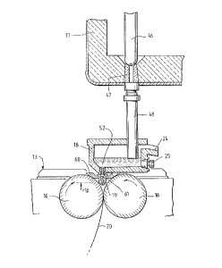
Delivery nozzle 19 is formed as an elongate body
made of a refractory material such as alumina graphite.
Its lower part is tapered so as to converge inwardly and
- 6 - 2069~5~
downwardly so that it can project into the nip between
casting rollers 16. A mounting bracket 60 is provided to
support the nozzle on the roller carriage frame and the
upper part of the nozzle is formed with outwardly
projecting side flanges 55 which locate on the mounting
bracket.
Delivery nozzle 19 has an upwardly opening inlet
trough 61 to receive molten metal flowing downwardly
through the openings 52 of the tundish and a metal flow
passage 62 extending from the bottom of trough 61
downwardly to a metal flow outlet slot 69 which extends
longitudinally of the nip between the casting rollers. In
accordance with the present invention, inlet trough 61 is
defined between a substantially vertical side wall surface
63 and an opposite side wall surface 64 which slopes
downwardly and across the trough to the upper end of the
metal flow passage 62. Accordingly, the bottom of trough
61 and the upper end of flow passage 62 are displaced
laterally from the central plane of the outlet nozzle which
contains the outlet slot 69.
Molten metal falls from the outlet openings 52 of
the tundish in a series of free falling vertical streams 65
which are intercepted by the sloping side wall surface 64
of the inlet trough at an acute angle of impingement such
that the molten metal tends to adhere to the sloping side
wall and to spread into the form of a sheet 70 flowing down
the side wall surface. It has been found that with correct
positioning and sloping of the side wall surface it is
possible to cause the downwardly flowing molten metal to
quickly and smoothly adhere to that surface with little
splash and turbulence. More particularly, it has been
found that with impingement angles of between 10~ and 50~,
and preferably between 20~ and 40~ the cohesive forces
between the molten metal and the refractory material of the
nozzle produce a sufficient "wetting" action between the
metal and the refractory material to cause the molten metal
to quickly and smoothly adhere to the wall surface 64 to
produce a smooth flowing sheet 70 along the length of the
nozzle so that the kinetic energy of the falling metal is
rapidly but smoothly reduced.
- 7 ~ 2069258
Wall surface 64 is curved downwardly and inwardly
of the trough so as to direct the flowing sheet of metal to
the upper end of outlet passage 62 with progressively
increasingly slope away from the vertical direction so as
to enhance this progressive reduction of kinetic energy in
the flowing sheet. More particularly, the wall surface
curves progressively from an angle of about 20~ from
vertical at the upper end of the wall to an angle of about
70~ from vertical at the bottom of the trough 61. The
molten metal streams 65 are intercepted by a mid-part of
the wall surface at an impingement angle of about 30~.
Metal flow passage 62 has an upper curved portion
66 which bends back toward the central plane of the nozzle
against the transverse deflection of metal flow in the
trough. This upper portion 66 leads smoothly into a lower
vertical portion 67 which extends down to the outlet slot
69. The curved upper part of flow passage 66 further
reduces the kinetic energy of the flowing metal by
deflecting that flow transversely of the nozzle back
against the direction of deflection in the inlet trough. A
further reduction of kinetic energy is achieved by a
discrete constriction 68 in the vertical lower portion 67
of the flow passage 62.
~ The illustrated nozzle achieves a three stage
reduction of kinetic energy. In the first stage, kinetic
energy is reduced by the capture of the stream in a sheet
on the wall surface 64 by wetting action or cohesive forces
between the metal and the wall surface and the simultaneous
lateral deflection of the flowing metal away from the
vertical. In the second stage there is a further reduction
due to the deflection of the stream transversely of the
vertical direction against the transverse direction of the
flow in the trough. The constriction 68 in passage 62
above the outlet slot provides a third stage reduction. It
has been found that this progressive multi-stage reduction
of energy can be such that it is not necessary to have a
narrow slot to build up a molten pool in the nip between
the casting rollers and it is possible to run the equipment
with a wider outlet slot than hither to. Moreover,
localised widening of the outlet slot on preheating of the
2069258
-- 8
refractory material can also be accommodated without
- causing defects due to uneven flow conditions as
experienced with previous equipment.
Figures 6 and 7 illustrate a modification to the
delivery nozzle in which the side wall surface 64 has a
surface pattern in the form of a series of parallel
corrugations or undulations 64a extending along the trough
and transverse to the direction of the falling streams 65.
The corrugations 64a promote spreading of the molten metal
across the surface 64 transverse to the general direction
of flow of the metal and so assist in the rapid
establishment of the continuous flowing sheet 70 and
reduction of the kinetic energy of the flowing metal. As
in the previous embodiment the wall surface 64 curves
downwardly and across the trough with increasing sope to
the vertical and apart from the provision of the
corrugations 64a the nozzle may be entirely the same as
that illustrated in Figures 4 and 5.
In a typical ferrous caster constructed in
accordance with the invention, the tundish openings may be
circular openings of 8mm diameter arranged at 50mm spacing.
The outlet flow passage 62 may typically be lOmm wide at
its upper end increasing to a width of 15mm upstream of the
constriction 68 and reducing to 1 to 7mm at the outlet
slot.