Note: Descriptions are shown in the official language in which they were submitted.
3 ~ ~.
SYRUP DOSING VALVE FOR USE IN INSTALLATIONS FOR THE
PREPARATION OF FLAVOURED CARBONATED BEVERAGES
5 FIELD OF INVENTION
The present invention relates to installations
for the dispensing of carbonated beverages prepared by
adding flavoured syrup in a suitable proportion to
carbonated or soda water, consisting of an admixture
10 of plain water and CO2 gas, as found in restaurants,
bars, hotels and the like.
BAC~G~OUND OF THE INVENTION
Such installations typically include a
15 water source, a vessel of pressurized CO apparatus for
mixing the CO2 with the water for making carbonated
water, and exchangeable containers or vessels ~or the
flavoured syrup supplied by the syrup manufacturer.
For the purpose of better understanding
20 the object of the present invention, reference shall
be made to Fig. 1, schematically illustrating a
typical layout of installations of the kind referred
to abov~.
Hence, the installation comprises a water
2~ source 10, a pressurized vessel containing caxbon-
dioxide gas 12 and apparatus 14 for admixing and
dissolving the CO2 gas 12 in the water from source 10.
The installation further includes the necessary
devices for mixing the carbonated water with the soft
7~ ~ 1
, _ . ~
drink syrup contained in a syrup container 16. ~s
schematically shown, the dispensing machine head
generally denoted 20 is normally activated when filler
arm 22 is moved as by cup 24. A solenoid 26 opens a
5 shut-off valve 28 and simultaneously actuates a
carbonated water pump 30 and syrup pump 32
thereby controlling the flow of carbonated water and
syrup respectively, in pre-determined proportions.
Normally the proportion between carbonated water and
10 syrup is 5:1. The mixture regulated by water valve 34
and syrup valve 36 is then dispensed via dispenser 38
to spout 39. These installations, with minor changes,
are widely used all over the world.
It has recently been desired, by the beverage
15 producing companies leasing such installations, to
incorporate means for completely disabling the
installation once the supply of syrup is interrupted,
for example, when the syrup reservoir 16 has been
exhausted. Since the installation was leased ~or the
20 supply of a beverage based on the syrup produced by
such leasing company, it should not be used
for dispensing carbonated watex which could be then
consumed on its own or to which syrup may be added
externally. The installation should thus be
25 operable only when the syrup reservoir has been
refilled or replaced with the leasing company's syrup.
Several solutions have been proposed to solve the
problem. One solution incorporates a level indicating
device 40, placed in the syrup reservoir 16,
operatively connected as symbolized by line 42, which
operates solenoid 26 so as to disable the operation of
the shut-off valve 28, namely, keeping it closed once
the level of syrup has reached the bottom of the
5 reservoir 16.
According to another proposition, a pressure
sensitive element 44 is operatively connected from the
syrup supply lins 46 to the mixing head of the
machine, downstream of the pump 32. The device 44
10 similarly disables operation of the shut-off valve 28
through solenoid 26 once pressure in the line 46 drops
as a result of the syrup reservoir becoming empty.
These two proposals suffer from the same
disadvantage, namely that changes must be applied to
15 the installation, remotely and outside the machine
head 20. In the first example an electric cable must
be connected (42) to the head of the dispensing
machine 20 on the one hand and to the syrup reservoir
16 on the other hand, the reservoir being remotely
20 located therefrom. According to the second proposition
the syrup pipeline must be interrupted so that the
device 44 could be included therein.
It is thus the major objec~ of the invention to
provide means for controlling operation of the
25 carbonated soft drinks dispenser, with minimum
intarference to the construction of the installation
as a whole.
It is a further object of the invention that the
component part of the installation included in the
2 ~
dispenser head can be easily replaced by a modi~ied
component achieving ~he desired result.
It is a still further object of the invention to
modify the construction of the syrup dosing adjusting
S element, associated with the syrup control valve,
which element would be the replacable component
capable of achieving the goal of the present
invention.
10 SUMMARY OF THE INVE~TION
According to the invention there is provicled an
improvement to installations for the dispensing of
carbonated flavoured beverages by the admixture of
flavoured liquid syrup with carbonated water, the
15 installation comprising a water source, a pressurized
C2 supply source, a syrup supply source, a control
valve for regulating the flow of carbonated water, a
control valve for regulating flow of the syrup, a
mixing head wherein the carbonated water and the syr~p
20 become admixed and dispensed through a dispensing
spout and an electrically controlle~ shut-off v~lve
normally closing the dispensing spout, the sald syrup
flow control valve comprising a housing with an inlet
and outlet for the syrup, a fixed cylinder with a
25 series of peripheral openings in communication with
the outlet, a floating cup-shaped plunger within the
cylinder, for partly closing the said openings, as a
function of the syrup pressure applied to the bottom
of the said plunger through the said inlet, an orifice
~$~
at the bottom of the plunger, through which the syrup
is admitted into the plunger to be discharged through
the said cylinder peripheral openings and ~ counter-
force compression spring acting against the plunger by
5 a screw-threaded adjusting pin having a head portion
accessible for rotating the pin and thereby adjusting
the quantity of syrup supplied to the mixing head, the
improvement of providing pressure sensing means
mounted on the said head portion, in communication
10 with and responsive to the syrup inlet pressure
prevailing inside the said plunger, operatively
coupled to means for disabling the said shut-off
valve, thereby preventing use of the installation upon
a pressure drop sensed by the said pressure sensing
15 means.
According to one preferred embodiment of the
invention the pressure sensing means comprise a
diaphragm operated electric switch, one side of the
diaphragm communicating with the i.n~erior of the
20 plunger via a throughgoing bore formed in the
adjusting pin.
BRIEF DESCRIPTION OF THE DRA~INGS
Further details and advantages of the invention
25 will become more clearly understood in the light of
the ensuing description of a preferred embodiment of
the invention, given by way of example only with
reference to the accompanying drawings, wherein -
5 ~
Fig. l is a schematic layout of a dispensing
installation;
Fig. 2 is a cross-sectional view of the syrup
control valve of conventional design;
~ig. 3 is a cross-sectional view of syrup control
valve including the improvement according to the
present lnvention;
Fig. 4 is a modi~ication of the valve in Fig. 3
(the remaining parts and components of the system
10 being omitted); and
Fig. 5 is a further modification of the valve of
Fig. 3.
DETAILED DESCRIPTION OF THE PRE:FERRE:D EMBODIMENTS
In Fig. 2 there are shown only the parts of the
syrup supply control valve, which are relevant for the
purposes of describing the features of ~he present
in~ention. It should be borne in mind that the
carbonated water supply control valve 34 and the syrup
20 supply control valve 32 are essentially of an
identical construction, the two valves being located
in a common housing made of injected plastic
construction, combined with the solenoid operated
shut-off valve mixer 28 and supplied as such by the
25 manufacturer of such installations (for example, the
Cornelius Company of Anoka Minnesota USA).
The invention is therefore descrl~ed with
application to this model, being the most popular and
widespread. In more detail, the syrup control valve
2~3~
,,
36 comprises a housing 52 which defines an inner
cylindrical wall 54, a syrup inlet 56 and outlet 5i8.
The housing as ~ whole (including that of the
carbonated water valve (not shown~) is separable and
5 mountable to a chest plate of the dispenser head by a
plug 60 in the conventional manner. Within the
cylindrical wall 54, there is seated and sealed
thereagainst, a fixed cylinder 62 (which is
manufactured from ceramic material so as to achieve
10 the precision required~, opened at its top and bottom
sides 64 and 66 by being seated on one or more
projections 68 at a distance 'S' from bottom wall 70
of the housing.
Thus, syrup entering the inlet 56 can reach the
15 interior of the cylinder 62. Within that cylinder, a
cup shaped plunger 72 (also manufactured from ceramic
material) is freely seated, having a circular wall 74
and a bottom wall 76 with an orifice 78. The cylinder
62 further comprises a series of peripheral openings
20 80, deployed around the circumference at a distance
somewhat higher than the height of the plunger 72, the
arrangement being such that when the plunger is
displaced upwards, it is adapted to close the series
of openings 80 and therefore regulate up to complete
25 cut-off the supply of syrup to the outlet 58.
A cover 82 is seated hermetically closing the
inner cylinder 54 of the housing 52 and held by
disman~able clamp 84. The cover 82 has a female screw
thread adapted to receive an adjusting pin 86 with
~$~3~1
square head 88. The adjusting pin 86 is provided with
seal ring 90 and is therefore sealed against leakage
of the syrup from within the cylinder 54, but is
displaceable along inner cylindrical wall 92 oE the
5 cover member 82.
A compression coil spring 94 is placed between
the inner end of the pin 86 and the bottom wall 76 of
the plunger 72.
It will be thus readily understood that the
i0 dosing or control of the amount of syrup allowed to be
passed through the valve 36 is adjusted by rotating
the pin 36 thereby applying a smaller or greater
strain force against the plunger 72. On the other
hand, the plunger is pushed upwards by the inlet
15 pressure of the syrup entering the inlet 56 and
through the orifice 78 into khe in~erior of the
plunger 72. Thus, the plunger 72 attains a state of
equilibrium, the location of the plunger determining
the extent to which the openings 30 are closed or
20 opened. It should be noted that, once the main shut-
off valve 28 (Fig. 1) is opened, the pressure
prevailing in the outlet 58 and above the plunger 72
is close to - but still above - atmospheric pressure.
As already mentioned cylinder 62 and plunger 72
25 are made of ceramic material because of the high
degree of precision required.
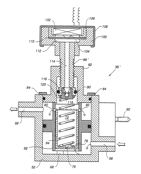
Turning now to Fig. 3 there is s~own the syrup
control valve including the improvement proposed
according to the invention.
2 ~
As aforementioned one object of the invention i5
to control operation of the carbonated soft drinks
dispenser so that the dispenser will cease to function
in the event of an interruption in the syrup supply; a
5 further object being to achieve this aim by
introducing minimum changes to the construction of the
system as a whole, and in particular to the .
construction of the control valve. Thus it is
proposed that the adjusting pin mar~ed 86 in Fig. 2
10 and 86' in Fig. 3 be altered thus enabling the
existing installation to be modified simply by
replacing the adjusting pin 86.
As shown in Fig. 3, the square head 88 of the
conventional adjusting pin 86 is altered and becomes a
15 base for carrying a head member 100 forming a housing
for microswitch 102 having an operating button 104.
The microswitch is seated within a circular shell 106
and preferably covered by a metal covering 108
although any other suitable encasement can be used.
Below the operator 104 of the microswitch 102 a
diaphragm 110 is clamped at its periphery as shown,
defining an air pressure chamber 112 thereundar. The
pin 86~ has a through-going bore 114 with a pulse
damping assembly of any conventional type provided at
25 its lower end. A damping assembly is needed in order
to avoid "hunting" or otherwise unstable operation of
the microswitch 102; this is particularly important in
cases where the syrup pump 32 (Fig. 1) is of the
"pulsating~ type, w.here the inlet pressure alternates
3 ~ ~.
~etween i~s higher level and zero level in ~ulses,
and, of course, at the beginning and terminatlon or
the pump operation.
In the e~bodiment shown in Fig. 3, the damping
S assembly consists o~ a ball ~ralve mem~er 116, sprin~
urged agai;nst restricted valve opening 118,
incorporated in a screw-~hr0aded insert 120. Either
the ball 116 or the valve seat is provided with a tiny
passage ( not sho~n ) through which the syrup is allowed
10 to leak downwards even in the "closed~' state o~ the
valve, thus acting as a damper, ra~her than a check-
valve.
lt will be readily understood that in this
manner, the inlet pressure prevailing within the
15 cylinder 72 is relayed to the chamber 112 via the
val~e seat opening 118 and ~he bore 114, the
arrangement being such that once a pressure o~
predetermined amount is available the diaphragm 110
will o~erate the microswitch 102 and if the in
20 pressure drops below a predet~rmined leveL the
diaphragm will reLieve the operator 104 and the micro-
switch wiL1 resume its normal (non activatPd)
position.
The operation of the modiIied syrup control val~e
25 (shown in Fig. 3) will now be ~xiefly described:
The microswitch 102, which is oî the normally
open type is connec~ed in series with,the solenoid 26
( Fig . 1 ) . As long as syrup is being supplied at the
re~uired pressur~ into the inlet 56, the solenoid 26
2~93~
operates the valve 28 in the normal manner. Upon
relief of the operator 104, due to a pressure dxop
occurring when the syrup reservoir 16 is exhausted,
the microswitch lQ2 will deactivate the solenoid 26,
5 closing the valve 28, irrespective of and overriding
the commands received by the operation of the filler
lever 22. The shut-off ~alve 28 will remain closed
and car~onated water alone will not be able to be
supplied.
In the modified embodiment illustrated in Fig. 4
(only the changed parts being shown), a tube 300 is
inserted into the bore 114 of the adjusting pin 286''
(86' in Fig. 3), communicating with the bore and
extending same down to a level next to the bottom of
15 cylinder 272. At the bottom 276 of the plunger 272
there is inserted an inverted cup-shaped insert 30
which is press fitted within an opening 304 at the
center of the bottom 276 (which is in fact an
enlargement of the orifice 78 in Fig. 3). The insert
20 302 ha5 an opening 306 with an annular cross-sectional
area 302, namely around the tube 300 equal to the
original cross sectional area of the orifice 78 in
order not to upset the proportional or dosing feature
of the device as a whole.
The tube 300 is preferably made of a non-rigid
material so that replacement of the conventional pin
86, by the modified pin 286'', can be~achieved
smoothly. In the case of the embodiment shown in Fig.
4, the inlet pressure prevailing below the cylinder
% ~
272 i~ relayed to the microswitch 102 (Fig. 3) via the
tube 300 and the bore 114, that is, upstream of the
orifice 78, which may add to the reliability of the
microswitch control operation.
Fig. 5 illustrates a further modified embodiment
to the valve shown in Fig. 3 (only the relevant
changed parts being shown). A damping assembly
generally denoted 400 is installed, adjacent to the
operating button 104 of the microswitch 102 at the top
10 of the through-going bore ~14 (in contrast to Fig. 3
where the damping assembly is installed at the lower
end of the through-going bore). The design of the
spindle 486' is somewhat changed, to form a
compartment 412.
An inverted, cup-like container 414 is provided,
being open at its lower end and having an orifice 418
formed within it's closed upper end 420. Both the
; lower and the upper ends are enclosed with tight
ritting diaphragm 422 and 424, respectively.
The container 414 is filled with a hydraulic
fluid 426, preferably an edible oil such as olive oil
which is light, natural and, in the event of any
unforeseen occurrence, will not pollute the drink
should it get mixed therewith and served.
In the case of the embodiment of Fig. 5, the
damping is effected by the presence of the fluid 426.
The inlet pressure admitted via the vaLve bore 114
causes the diaphragm 422 to be distorked convexly,
pressing the fluid 426 upwards and via the orifice 418
' ~ .
3 ~ ~
distorting convexly the upper diaphragm 424 and thus
pushing the button of the microswitch 102.
The damping assembly 400 illustrated in the
embodiment of Fig. 5 requires less parts than that
5 shown in Fig. 3 and by being in direct contact with
the microswitch 102 allows for a more stable
operation.
It has thus been established that by a most
simple operation, namely the exchange of one of the
conventional components of the system (the dosing
adjusting pin) by a modified component -- any existing
installation can be improved by gaining control over
the dispensing of soft drink syrup, for the beneit of
both the syrup producing and leasing companies and the
customer.
Those skilled in the art will readily appreciate
that various changes, modifications and variations may
be applied to the invention as heretofore exemplified,
20 without departing from its scope as defined in and by
the appended claims.