Note: Descriptions are shown in the official language in which they were submitted.
W(192/05031 PC1'/US91/fl7~'~1
_1_
ARTICLE STOPPING APPARATUS
Background Of The Present Invention
This invention relates to an article stopping
apparatus and particularly to such an apparatus for
receiving a series of overlaying and overlapping sheet-
s like articles and stopping movement of successive
articles to form a gap between successive batches or
groups of the articles.
In the processing of sheet-like members, a
web is sequentially cut into a series of sheet-like
members for subsequent processing. In many in-line
processes, the sheets are assembled in a continuous
line of overlapping sheets with each of the following
cut sheets moved into overlapping engagement with the
preceding downstream sheet, generally referred to a
shingling process. The shingled sheets may be divided
into sequential batches for providing a precise number
of sheets assembled to a suitable stacking apparatus.
In the forming of batches, various systems have been
proposed including a stopping apparatus for
progressively slowing down and generally stopping the
sheet at the upstream end of a batch and progressively
stopping subsequent sheets with an increased overlap of
succeeding sheets to provide a concentrated group of
the sheets with the increased overlap which are then
Z5 rapidly fed from the stopping apparatus as at least a
part of a batch to a starker or other processing
mechanism or apparatus.
For example, the stepping apparatus may
include an overlying member which is moved downwardly
3U and progressively into abutting engagement with the
incoming stream of shingled sheets on the conveyor
thereby stopping the feed of the downstream sheet on
the conveyor while allowing the controlled and partial ,
increased movement of the upstream sheets over the
35 conveyor to increase the overlap prior to terminating
of their movement and thereby defining the leading end
of a batch. Once a selected gap is created with
rV0 92106031 P~,'g°~~J~~~G~7~'~~
-
2
respect to a preceding batch, the overlying stopping
membe~r'~is raised and sheets are released and the
batched sheets are allowed to rapidly move from the
stopping apparatus. As the leading sheet o:E the new
batch approaches the discharge end of the apparatus,
the overlying member again moves downwardly into
engagement therewith to prevent its continuous movement
and the apparatus again recycles to effect the desired
increased overlapping within the next batch in the
forming of a new batch.
~U.S. Patent 3,337,666, which issued March 19,
1968 discloses a similar means in combination with
means for holding of the articles in spaced relation to
the conveyor to assist in the botching process.
These and other patents disclose various
botching systems generally using some form of a
mechanical stopping mechanism. The mechanism which
holds the shingled sheets in a retarded position on the
conveyor of course are subject to relative movement
between the sheets and the conveying mechanism. This
may be undesirable in certain applications particularly
those where the underside of the sheet can raise
printed matter or other matter which might be subject
to damage by the relative motion. Further, such
mechanical devices rely on a mechanical intersngagement
generally with the leading edge of the sheet and
require relatively complex mechanisms which are subject
to various maintenance cast and mechanical failures.
There exists a need for an improved system
for holding of the shingled sheets in appropriate
fashion to allow the increased overlapping with a
minimum complexity of apparatus and yet which operates
at high speed with reliable stopping of the sheets and
which is particularly adapted to in-line processing of
the sheets.
'~i'~ 9~/06(i31 PC,°1"/B.JS91/07071
-3-
Summary Of The Invention
In accordance with the invention, a conveying
unit receives overlapping articles or members to be
separated in sequential and spaced batches which are
delivered to a downstream unit such as a stacking
station. The conveying unit includes a delay unit
having a fluid pressure coupling unit interposed
between the incoming stream of members and the
downstream unit for temporarily stopping the movement
of succeeding members and accumulating the incoming
members during the transfer and processing of the
preceding rnembers to thereby separate articles within
the delay unit from the preceding articles. In
accordance with a particularly practical embodiment of
the invention, the conveying unit includes a plurality
of laterally spaced conveying elements. A plurality of
control units which lift and hold the members are
interposed between the conveying elements. The lift
and hold elements are mounted for vertical movement,
from below the conveying elements, upwardly above the
conveying elements to raise the overlapping members
from the conveying elements and remove the moving force
therefrom, hold the elements and successively grip the
members in fixed position. The hold elements are, in a
preferred construction, vacuum elements providing
individual vacuum gripping portions longitudinally
spaced of the lift and hold unit. 7.'he vacuum elements
are successively activated to estab::.ish a controlled
increased overlapping of the individual members within
the delay unit to thereby progressively stop the
incoming members during the stacking or other
processing of the preceding members. The lift and hold
units are then lowered and the vacuum released, with
the released members rapidly transferred from the delay
unit to the downstream unit. The stream of members
continues until a selected number of members to form a
stack has moved through the hold conveying unit and the
W~ 92/06031 PCT/LJS91/07071
cycle is repeated. In the embodiment including a
stacking unit, the stacking unit includes a conveying
unit for transport of the increased overlapped members
into a vertical bottom stacker. The members move
successively into a vertical stack with the members
dropping downwardly on a support structure during the
separation period of the next batch.
In the preferred construction, the apparatus
includes a plurality of laterally spaced conveyor belts
mounted on a common drive system for simultaneous
movement. The overlapping incoming members are carried
in a horizontal plane through the apparatus.
Interposed between the belts are elongated vacuum bars,
each of which includes a substantial plurality of
longitudinally spaced vacuum openings or nozzles. Each
bar is similarly coupled to a common support for
correspondingly raising and lowering the vacuum bars.
The vacuum bars are supported in a generally inclined
orientation with the downstream or leading end located
above the upstream or trailing end of each bar. The
bars are pivotally mounted at the opposite ends for
vertical raising and lowering the vacuum openings or
nozzles secured to the bar. In a stopping sequence,
the associated leading end of each bar is raised to
locate the initial vacuum opening or nozzles above the
plane of the conveying elements and to thereby
simultaneously raise the incoming overlapping
members. The initial or downstream vacuum nozzles grip
the trailing position of the first member of the
incoming members to terminate the forward movement
along the conveying path. The opposite end of the
vacuum bars include a conjointly actuated raising and
lowering unit for progressively raising of the upstream
end of the vacuum bars above the level of the conveying
elements or belts. As a result of the inclined bar
orientation, successive openings or nozzles move into
engagement with the incoming members and in particular
WO 92/0b031 PCT/1~~91/07~71
-5-
engage the trailing end portions of the members to
effectively terminate the movement of successive
members as they are raised from the belt elements with
an increased overlapping condition relative to the
immediately preceding member. Thus, as each leading
member of the successive members is engaged by the
vacuum element, its movement essentially to rminates.
The following members however are continued to be moved
by the conveying belts and thus move into further
overlapping engagement with the immediately preceding
stopped member. The overlap increase continues until
such time as an aligned nozzle moves upwardly into
raised and holding engagement.
In an actual commercial embodiment, each of
the vacuum bars include a common tubular member with a
rectangular bar secured to the tubular member.
Openings are longitudinally spaced in the rectangular
bar and the top wall of the tubular member. The vacuum
source is secured to the downstream or leading end of
the tubular member.. A piston is journaled in the
tubular member and the piston rod projects outwardly of
the upstream or trailing end. A separate vertical
positioning unit is secured to the vacuum bars for
simultaneously positioning of the leading end of all
vacuum bars and a second vertical position unit secured
to the outer end, of the piston rod and includes a
powered linkage mechanism which simultaneously serves
to raise and lower the rod and thereby pivot the vacuum
bar about the forward raised end in a progressive
defined manner while simultaneously moving of the
piston rod to establish and effect the desired
successive opening and closing of the successive vacuum
openings. In this manner, the system provides a means
for effectively lifting of the members to remove the
forward force on the members to more readily permit
stopping and holding of the members by engagement with
the vacuum openings, and lowering of the members to
W~ 92/06(!31 PCT/~J~~ld~7~'71
;':
again apply the forward conveying force on the batch of
members..
If desired or necessary, a mechanical holding
device may be mounted engaging the leading member in
each group or batch, and may be mounted to the opposite
or top side of the overlapping members within the
separation unit. Such an element rnay, for example,
include a wheel unit located above the upstream end of
the vacuum bar unit, or a simple angled bar or belt
adapted to further engage the upper and leading ends of
the members in a progressive sequence to assist in the
holding of the members against forward movement.
The method arid apparatus of the invention
provides a highly effective means for controlling the
batch flow of overlapping members in a high speed
processing line such as encountered in forming of
signatures and other printed matter in the graphics art
industry as well as in other sheet processing systems.
Brief Description Of The Drawings
The drawings furnished herewith generally
illustrate the best mode presently contemplated for the
invention and are described hereinafter.
In the drawings:
Fig. 1 is a side elevational view of a sheet
forming and stacking apparatus incorporating an
embodiment of the present invention;
Fig. 2 is a plan view of the stacking and
hatching apparatus shown in Fig. 1;
Fig 3 is an enlarged sectional view taken
generally on line 3-3 of Fig. 2;
Fig. 3A is an enlarged view of a lifting
control unit shown in Figs. 1 and 2; and
Fig. ~A-4C is a series of simplified views
similar to Fig. 3 illustrating the sequential operation
of the hatching apparatus and stacking apparatus shown
in Figs. 1-3.
WO 92/06031 PC.I'/LJS91/07071
_~_
w
Description Of The Illustrated Embodiment
Referring to the drawings and particularly to
Fig. 1, a sheet assembly apparatus 1 is illustrated for
assemblying a continuous series of individual sheets 2
into a series of stacks 3 of sheet 2. An input
conveyor 4 transports a continuous stream of shingled
or overlapping sheets 2, which have been formed and
assembled onto conveyor 4 in any suitable apparatus.
In-line machine, not shown, are known in which sheets 2
may, for example, be farmed from a web of indefinite
length which is passed through a rotary cutter to farm
a series of sheets which are then passed through a
shingling apparatus to form the sheets 2 as shown on
conveyor 4. The sheets 2 may be individual members or
multi-page members such as signatures and generally are
to be gathered into like numbered groups, shown as
stacks 3 for subsequent processing. A stopping unit 5
for separating successive botching sheets, is mounted
to receive the stream of shingled sheets 2 and
momentarily stops or delays movement of the overlapping
sheets 2 downstream onto a transfer conveyor 8 to form
a gap 8a between successive batches 7 of sheets
transferred into the stack 3. During the stopping
period, the sheet overlap is increased to permit
continued movement of the incoming sheets prior to
discharging of each batch 7 onto a transfer conveyor
8. A downstacker 9 is mounted immediately downstream
of the conveyor 8 and receives the batch 7 of shingled
sheets 2 and stacks the sheets in the downstacker 9 in
the illustrated embodiment to form stacks 3. During
the transfer and stacking of the batch 7 from conveyor
8 to the downstacker 9, a new batch 7 is formed with
the leading or downstream sheets 2 held at the
separation and stopping apparatus or unit 5. The
present invention is particularly directed to the
construction and operation of the unit 5 to establish
and maintain an accurate sequential formation of a gap
WO 92/06031 PG'1'/U~91/07071
_ _
.: ;
8
,:;.;~.
~~~~~3~..y .
between successive batches 7 of sheets 2. Each batch 7
may consist of the sheets 2 held on the conveying unit
of the unit 5 and any additional upstream sheets 2, .
with the sheets fed continuously through the stopping
unit 5 to the conveyor 8. When a selected number of
sheets have passed from unit 5 and thus to conveyor 8,
unit 5 is operated to stop further movement of sheets 2
from unit 5 to conveyor 8, and thereby form gap 8a
between the downstream batch 7 and the upstream batch
7, the leading sheets of which are delayed within the
downstream end of unit 5.
Generally, in accordance with the illustrated
embodiment of the present invention, the stopping unit
5 includes a belt conveyor 10 for transport of the
sheets 2. The conveyors 4 and 8 are shown integrally
formed with the conveyor 10 in the illustrated
embodiment and includes a plurality of laterally spaced
conveying members which are mounted to transport the
overlapping shingled sheets 2 received from the infeed
2U conveyor 4 to the transport conveyor 8 and downstacker
9. The conveyor 10 is illustrated as an endless belt
structure having a plurality of laterally spaced belts
10a moving in a common horizontal plane for transport
of the sheets 2 in such plane. Interposed between the
laterally spaced belts lOa is a control assembly
including a plurality of control units 11 forming a
stopping control unit. Each of the control units 11 is
shown including a rigid lifting bar having a first
position located in or below the plane of the conveyor
unit. In this position, the units 11 allow essentially
unobstructed motion and movement of the overlapping ,
sheets 2 through the stopping unit 5. The control
units 11 are adapted to be raised upwardly above the
level of the conveyor belts 10a, as shown in Figs. 3,
4A, 9B and 4C. The upward movement and positioning of
the control units 11 is initiated at the downstream end
of the sheet flow and progresses upstream to the infeed
'W~ 92/06031 PGTIUS~li'n7~f'7~
~g-
F: >; :;"
end of the unit 5. As a result, the overlapping sheets
2 are progressively raised from the belts beginning
with the most downstream sheet. As the sheet 2 is
raised from the belt, the forward force on the sheet
established by the conveyor belts is removed. The
trailing sheet is still receiving the forward
progulsion forces of the belts and thus moves upwardly
into increased overlapping relationship to the
downstream or preceding sheet.
In addition to the lifting o.f the bars and
thereby sheets 2, a fluid holding force is specially
applied to the raised sheets 2. Generally in a
preferred and optimum construction, a vacuum holding
assembly is incorporated into and associated with the
control units 11 and includes longitudinally spaced
vacuum coupling nozzles 12, each of which establish a
vacuum holding force on the exposed bottom or underside
trailing portion of each sheet 2, in synchronism with
the raising of such sheet from the conveyor belts. The
vacuum force is located to positively grip and hold
each sheet 2 in fixed relation to the preceding
overlapped trailing sheet to establish an essential
precise increased overlap of successive sheets. This
action permits continued movement of the conveyors and
the incoming sheets 2 with an accurate assemblying of
the leading sheets of each batch 7 within the unit 5.
The unit 5 thus proceeds to assemble the plurality of
incoming sheets 2 in increased overlapping position.
When a preceding batch 7 has moved through conveyor 8
for proper stacking and removal such that a new batch
can be transferred to conveyor 8, the control units 11
are lowered and the newly formed batch 7 is released
and rapidly moved as a continuous stream from the unit
5 and the incoming conveyor 4 to conveyor 8. The unit
5 recycles to form the leading end of another batch
after the last sheet of the preceding and previous
batch is transported to conveyor 8 for feeding to the
downstacker 9 or otherwise processed.
W~ 921OG03~ PCT~%J~9~~~79f7~
_ !'fig.:
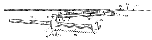
Generally, in the illustrated embodiment of
the invention, each control unit 11 includes a tubular
lift member 13 with the nozzles 12 secured thereto.
The members 13 are pivotally mounted at the downstream
5 end of the unit 5 as by a pivot unit 14. A piston unit
is slidably mounted in the tubular lift member 13
and projects outwardly at the upstream end. A common
reciprocating drive assembly 16 is secured to the
projecting end of the piston unit 15. The drive
:LO assembly 16 operates to reciprocate the separate
pistons 17 within the tubular members 13, and
simultaneously raises and lowers the members 13 about
the forward pivot unit 14. A vertical positioning unit
18, shown as a vertical reciprocating motor unit, is
1.5 coupled to the pivot unit 14 for raising and lowering
of the downstream end of the control bar. The pivot
unit 14 raises the downstream end of the control unit
above the conveyor unit and particularly the conveyor
belts.
The vacuum assembly includes a vacuum source
19 coupled to the downstream end of the tubular
member. The member 13 has an upper vacuum bar 25
secured to the member 13 with the nozzles 12 formed by
longitudinally and equally spaced openings along the
length of the bar and member 13. The nozzle openings
12 are located in the upper plane of the bar 25 which
serves to engage and support the aligned trailing end
portion 20 of the sheets 2. As the piston unit 15 is
retracted, the vacuum pressure from the vacuum source
3U 19 is transmitted through the nozzle openings 12 to the
aligned sheet 2 which is thereby held in a
substantially fixed position on the raised vacuum bars
25.
The members 13 with bars 25 are cyclically
pivoted to lift and progressively stop the leading
sheets 2 of a batch 7, and then reversed to drop the
vacuum bars and place all raised sheets onto the
vv~ 9aio6om ~c°rrus9vo7om
~. <. 11
i ~ ~ ..4
conveyor. The batch 7, including sheets in unit 5 as
well as following sheets 2 to form a proper numbering
of sheets, are then propelled through the unit 5 into
the transfer conveyor 8.
Thus, upon reversing of the system, the
downstream ends of the member 13 via vacuum bars 25 are
lowered beneath the plane of the conveyor belts 10a,
and simultaneously with the downward pivoting, the
vacuum is stopped or operatively decoupled, whereby the
1.0 holding vacuum force is removed and the sheets 2 in
unit 5 are released. As a result, the batch 7 of
sheets 2 are lowered onto the high speed conveyor belts
10a of the unit S and move a stream onto the transfer
conveyor 8 to the downstacker 9. The transfer conveyor
8 withdraws the batch 7 and as the last sheet of the
total batch moves from the leading end of the control
units 11, the stopping apparatus or unit 5 recycles to
initiate formation of the leading end of another batch
7. The preceding batch thus moves forwardly and forms
a gap with respect to the overlapping sheets being fed
into a new batch 7 on the unit 5.
The transfer conveyor 8 is shown as a part of
the hatching conveyor 10. A separate conveyor, which
is operated in synchronism with the unit.5, may also be
used to rapidly transport the sheet batch from the
stopping unit 5 to the downstacker 9.
The illustrated downstacker 9 includes a
receiving receptacle 21 for successive receipt of the
sheets 2 from the conveyor 8. The individual sheets
are passed successively from the conveyor 8 into the
receiving receptacle 21, and the sheets drop by gravity
into a stack 3. The receptacle 21 is mounted for
vertical movement in synchronism as the sheets
accummulate. The final stack 3 is removed as by
lateral transfer on a conveyor 23 for transfer from the
stacking station, and a new batch 7 transferred from
the unit 5 and conveyor 8 into the receptacle 21.
w~ 9a~oso3i ~c°rms~~oo707~
-12-
f...,
As noted previously, the present invention is
particularly directed to a stopping unit 5, and the
illustrated embodiment is now described in detail. The
other components of the system may include any known or
other suitable structure and the illustrated
embodiments are only described to fully and clearly
describe the illustrated embodiment of the batching
unit.
More particularly in the illustrated
embodiment of the invention, the illustrated hatching
unit 5 and. particularly the conveyor belt unit 10
includes a plurality of laterally spaced endless belts
10a. Each belt 10a is looped about spaced pulleys or
rollers 24 at the infeed end and the downstream or
outfeed end and define a horizontal transfer run for
carrying of the overlapping or shingled sheets 2
through the unit 5. The bottom run of the belts 10a
are shown looped about a drive pulley or roller 24a
secured below and generally adjacent the downstream end
of the unit. The bottom run of the belts are driven
through a suitable gear coupling to the main line of an
in-line system or connected to a separate drive in such
a manner as to provide correlated movement with other
parts of the line. All belts 10a are driven at the
same surface speed to provide a proper and aligned
movement of the sheets into and through the stopping
unit 5.
Each of the control units 11, as previously
noted and described, is mounted within the lateral
space between adjacent belts 10a. Each unit 11, as
mare clearly shown in Figs. 3 and 3A, includes,the
illustrated tubular member 13 having the rectangular
nozzle bar 25 welded or adhesively affixed to the top
of the tubular member 13r with the nozzle openings 12
~5 formed therein in alignment with openings in member
13. Bar 25 has a flat top wall with a surface cover
26, such as a belt material, which is suitably secured
W~ 92106031 P~.'I'/1LJ~91407071
-13-
as by an adhesive or otherwise to the top wall to
provide proper high friction support of the sheets 2.
The downstream end of the tubular member 13
is closed by an end plug 27 to form a vacuum chamber
within the bore 28 of the tubular member 13. The plug
27 projects outwardly to the pivot unit 14. A vacuum
connector 29 is secured to the underside of the leading
end of tubular member 13 adjacent the end of the bar 25
and is connected through a suitable line 29a, such as a
flexible vacuum line to a vacuum source 19. An
electrically controlled valve 30 is shown connected in
the vacuum line 29a to selectively establish the vacuum
during the stopping cycle and to rapidly remove the
vacuum at the end of the stopping cycle.
~lith the vacuum present in the tubular member
13, the piston 17 controls the coupling of the vacuum
nozzle openings 12 to the bar 25. The piston 17 is
provided with an 0-ring seal 30a on its inner end
portion and defines a sealed sliding connection within
the bore 28 of the member 13 and thereby defines a
sealed vacuum chamber between the piston and the end
plug 27 of the member 13. The piston 17 is secured to
a piston rod 31 which is connected to drive assembly
16. The assembly 16 operates to move the piston and
successively uncover the discharge openings in the
nozzle bar.25. As each opening 12 is uncovered, the
desired vacuum pressure condition is transmitted via
the opening to grasp and firrnly hold the sheet 2 to the
bar.
3~ The plug 27 is a rigid rod-like member which
projects from the tubular member, which extends
downstream slightly from the vacuum connection. The
power lift or positioning unit 18 is secured to the
lifting unit at the outer end of the plug 27. The
power lift 18 is shown including an air cylinder 32
having one end of the cylinder secured to the frame
structure and having an outwardly projecting piston rod
W~ 92/06fl31 P~I'l~J~y&~~7~9'~~
-14-
33 connected to the end of plug 27 by the pivot unit
14. The rod 33 extends into and is connected to a
piston 34 in cylinder 32 which is coupled to a suitable
supply 35 via an air control valve 36 of pressurized
air for raising arid lowering of the lifting unit. The
lifting unit 18 in the lowered position is inclined
downwardly at a selected angle from the pivot unit 14,
with the top cover 26 of the nozzle bar 25 below the
belts 10a.
The nozzle bar 25 includes the appropriately
spaced nozzle openings 12 which are connected to the
bore 28 via aligned openings in the tubular member
13. The plurality of openings 12 terminate in the
common plane of the top cover 26 of the nozzle bar 25
and are spaced to the trailing end portion of sheet 2,
in the stream of incoming sheets. The holding force on
the sheet 2 is sufficient to hold the sheet abutting
the bar and preventing further downstream motion.
The nozzle openings 12 are all
correspondingly formed and are longitudinally equally
spaced along the length of the bar 25 with at least one
opening I2 located for coupling to the trailing portion
of each overlapping sheet 2. Thus, depending upon the
degree of overlap provided within the incoming sheets
2, as shown as unit 5, ane or more of the vacuum
openings 12 of any one lifting member 13 will engage
the trailing portion of the sheet 2 as it is lifted
from the conveyor belts 10a and positively terminates
its movement.
As shown in Figs. 2 and 3, the upstream end
of the piston 17 projects outwardly of the upstream and
open end of the tubular member 13 and is connected to a
cross rod 31, common to all pistons 17.
The drive assembly 16 is similarly coupled to
-;35 each end of rod 31 and includes a link 37
interconnecting the outer end of rod 31 to a motor
driven linear rack 39. Movement of the rack 39
dV0 92/0631 1'CT/1U~91/07~71
--15-
~:
,.
produces a simultaneous pivoting movement of the
tubular member 13 about the downstream pivot unit 14 in
response to reciprocation of the rod 31 and piston 17
within the tubular member 13.
The apparatus thus functions to sequentially
form batches 7 of precisely the same number of sheets 2
which are transferred to the receiver 21 to form
successive stacks 3 of the same number of sheets.
The rack 39 includes a pair of spaced
1U journals 40 slidably mounted on a cam rod 41, which is
fixedly mounted to the machine frame. Rack 39 is
coupled via a coupling gear 42 to a suitable reversible
electric motor 43. The cam rod 41 is mounted at an
inclination to the horizontal plane of the conveyor
belts 10. In the illustrated embodiment, the rod 41
lies in a vertical plane. The cam rod 41 is oriented
below the conveyor belts, with the upstream end above
the downstream end.
In the initial or starting home position, as
shown in Fig. 4A, .the rack 39 is located on the lower
end portion of the cam rod 41. When the leading sheets
of a batch are to be held within the unit 5, the motor-
driven gear 42 is actuated and drives the rack 39
upwardly on the cam rod 41, simultaneously pulling the
piston 17 from the tubular member 13 and pivoting the
member about the raised pivot unit 14. The outward
movement of the piston 17 correspondingly varies the
size of the vacuum chamber, as showy. in Figs. 4A and
4C, to selectively and sequentially uncover the vacuum
nozzle openings 12. The rack 39 and the attached
pistons 17 move at a speed related to the belts 10a to
form and maintain the gap 8a between successive batches
or groups of the sheets 2 passed through the separating
apparatus or unit 5.
Referring particularly to Fig. 4B, the
members 13 and bars 25 have been raised by the raising
of the pivot unit 14 to lift the aligned downstream
W~ 92!05031 PGT/1JS91/07071
r r"'",:
-16
~~
sheets 2 from the belts 10a, with the rack 39 in the
initial position. In this position, the one sheet,
specifically identified by number 45, and particularly ,
the trailing portion of such sheet is aligned with the
first nozzle opening 12, which has been uncovered by
the simultaneous action of the motor 43 with the
pivoting to withdraw piston 17. The movement of this
one sheet 45 is therefore stopped. The upstream sheets
2 are moving at the speed of the belts !0a and the
immediately following sheet 46 moves upwardly over
sheet 45,.and thereby increasing the overlap. The
other following upstream sheets 2 correspondingly move
into a greater overlap downstream. All of the
preceding sheets 2 continue to move at the speed of the
belts 10a.
The downstream sheets 47 forming the trailing
end of the preceding batch 7 move from beneath the
sheet 45 and move the trailing end of the downstream
batch from the leading end of the next batch which are
now held in the separating unit 5, forming gap 8a, as
shown in Fig. 4C.
By appropriate moving of the piston 17
relative to belts 10a, the several sheets 2 in the unit
5 are similarly overlapped as shown in Fig. 4C,
resulting in gap 8a. After an appropriate length gap
8a has been formed, the pivot unit 14 is lowered to
release the raised sheets 2 onto the conveyor belts
10a, and the vacuum is simultaneously removed by
closing the vacuum valve or the like. The batch of
sheets is thus released to the belts !0a which move as
a new batch 7 from unit 5 onto conveyor 8, with the gap
8a therebetween.
A simultaneous reversal of the lift and drive
assembly 16 is initiated, with the lift unit 18
dropping the downstream end of the bars 25 and the
motor 43 reversing the movement of rack 39 and
interconnected pistons 17 to reset the lifting and
W~ 9z/Ofi031 P~I°~~.J~~fl/~~F~'~~
.. -17-
control units 11.
The rack 39 and the pistons 17 are reset, and
the appparatus is in condition to recycle and create
another gap when the total sheets of the new batch have
moved through the separating unit 5.
Any suitable control unit 48 can be provided
to control the several positions of the control unit 11
in relationship to the conveyor and sheet movement, as
diagrammatically illustrated.
The apparatus thus functions to sequentially
form the gap Ba between successive batches 7 of the
desired number of sheets 2, which are transferred to
conveyor 8 and therefrom to the receiver to form
successive stacks 3 of the same number of sheets.
Although the control units 11 are illustrated
as an integrated lift and vacuum unit, obviously
separate lift and vacuum elements could be provided
with appropriate location and positioning to effect the
functions of lifting of the overlapping sheets and
separately applying a holding force to the members
moving through a suitable apertured conveyor unit.
Thus, although shown as a belt conveyor, any other
suitable conveyor having spaced openings which permit
the lift of the members and the application of the
holding force may be provided. Further, if desired, a
top holding force could be used. For example, a top
bar, wheels or belt member, air pressure elements or
other devices mounted above the downstream end of the
vacuum bar to create a stopping force may be provided
to further improve the sheet stopping ability of the
apparatus. These and similar modifications can be used
within the scope of the definition of the various
means, control units and devices described and defined
in the claims. Thus, within the broadest concepts of
the present invention, the sheet stopping and gap
forming control unit includes the combination of means
to relatively position the overlapping incoming sheets
W~ 92/06031 1'CCl"~1JS91~~'0'71
_ 18 _ a;;~.
in spaced relation to a conveyor unit in combination
with a means for establishing a positive fluid holding
force on each sheet in a flowing stream to produce
increased overlapping of the sheets such that the
downstream sheets move therefrom to form a gap between
successive groups or batches of the sheets without the
necessity of changing the conveying units of the line
or having the stopped sheets or other such articles
held against the moving conveyor.
WO 92!06031 P~/LJS91/07071
-19-
~'~~~ ~~3
Various modes of carrying out the invention
are contemplated as being within the scope of the
following claims particularly pointing out and
distinctly claiming the subject matter which is
regarded as the invention.
;. n<
:. a: