Note: Descriptions are shown in the official language in which they were submitted.
2~
~eutsche Thomson-Brandt GmbH
7730 Villingen-Schwenningen
Hannover, Dec. 18, 1989
PTL -Sn~hl H 89/087
Method for tape tension adjustment
Video and audio recorders preferably store the
information on magnetic tape which is stored in a cassette
on two adjacent winding vessels. Hereby, the cassette is
inserted in such a way that the winding vessels actuated by
gravity lock in with suitable gudgeons of the drive
mechanisms of the reproduction device. With off-the-shelf
video recorders with a rotating head cylinder it is
necessary to draw the magnetic tape out of the cassette by
means of a 'threading' mechanism and, with the help of
guides, to place it against the perimeter of the head
cylinder. This threading process is performed by means of a
threading motor which places the magnetic tape into its
playing position, for example, by means of threading
carriages driven by means of a cam disc.
By means of a further motor which may also be designed
to be a capstan motor the winding plates are driven whereby
this drive operates, for example, through a tumbler gear
which is always coupled with the take-off plate whereas in
the reproducing operation the required tape tension is
maintaine-d at the feeding plate by a friction brake which is
designed as a brake band. For an even tape tension
throughout the whole length of the tape, the actual tape
tension is monitored by a tape tension sensor and evaluated
- 2 - 20~9~91
for an adjusted braking effect for the feeding plate
dependent on the position of the sensor.
The brake band must be released for the backward search
mode because it would tighten itself at the take-up plate
through the altered direction of winding, in this sort of
operation with known constructions. The release of the
brake band generally happens by the tape tension sensor
lever lifting off the magnetic tape. Therewith, the last
adjusted tape tension is given up and a tape loop develops
which must be taken up when the magnetic tape i5 started.
Consequently, with this sort of solution it is not easily
possible to achieve a single feed of frame (still picture)
with the change of direction of the magnetic tape from the
forwards to the backwards search mode.
A magnetic tape recorder is known from the not pre-
published patent application DE 39 35 150 in which the drive
for the winding vessels happens through a tumbler gear which
is driven from a planetary gear with an integrated slip
coupling whose effects are adjustable. Definite values for
the slip coupling are set for the various types of operation
in this recorder.
In the backward search mode, as already shown, the
mechanical brake band has no effect and a definite given
value for the tape tension must be obtained by the slip
coupling for good tape-head contact and therefore, with
changing tape winding diameters, a tape tension increase up
to four times as high follows regarding the whol length of
the tape whereby increased appearance of wear, particularly
to the magnetic tape itself through overstretching in
particular sections of the tape, can appear.
It i~ the object of the invention to show a method for
a magnetic tape device with which, on the one hand, with the
H 89/087
~ 3 ~ 2~69~91
reverse of the direction of rotation for the backward search
mode to maintain the last adjusted values for the tape
position and tension and, on the other hand, to attain a
suitable regulation of the tape tension for a consistent
tape tension in every position of the magnetic tape for this
type of operation.
This task is solved through the invention by the
features given in claim 1. Further advantageous
developments of the invention are given in the sub-claims.
In principle, the last adjusted values for tape
position and tension are maintained during the reversing
into the backward search mode through first arresting the
tape tension sensor lever in its last position. This
happens through a catch lever, for example, released by the
threading motor, which has a fixed pivot (fulcrum) and with
a crank arm makes contact with the tape tension sensor lever
through a spring effect. The catch lever engages a
particularly shaped surface of the tape tension sensor lever
whereby, the tape tension sensor lever and the brake band
which is coupled with the tape tension sensor lever are
first held in their position at the take-off (feeding)
plate.
For a good tape-head contact in the backward search
mode a larger transmission moment is required as opposed to
the normal reproduction operation because of the longer tape
distance between the driving capstan shaft and the driven
winding plate which means that the tape tension is also
higher in this sort of operation. The transmission moment
is adjusted by a slip coupling located in the driving path
which can be located, for example, in a set of gears, as
described in the above mentioned application DE 39 35 150.
Through the higher tape tension with the starting of the
backward search mode the tape tension sensor lever which is
H 89/087
- 4 - 2069891
in contact with the magnetic tape is moved in the direction
in which the brake band of the take-off plate, which now
operates as a take-up plate, is released. The excursion of
the tape tension sensor lever in the described direction is
possible despite the closed catch lever because the surface
on which the catch lever makes contact is formed in such a
way that the catch lever can glide on this surface with the
magnetic tape stretched tight and eventually reaches a
position in which the catch lever no longer makes contact
with th~ tape tension sensor lever. Thereby, the tape
tension sensor lever still lies on the magnetic tape and
follows the excursions of the magnetic tape.
In order to gain a consistent tape tension, regarding
the whole length of the tape, these excursions can be used
to gain a follow-up adjustment of the coupling effect. The
particular position of the tape tension sensor lever is
detected by sensors, for example, in the form of a light
barrier, in which a particularly-formed part of the tape
tension sensor lever is immersed. Control signals are given
out from the sensors which are evaluated in an electronic
circuit and given out to an electro-mechanical converter
which triggers the regulation of the coupling for the
resetting of the coupling effect. Thereby, the electro-
mechanical converter can be the threading motor which is
connected with the adjustable coupling via a lever
arrangement. Mechanical, magnetic (Hall elements) or
optical elementq can be installed as sensors. The use of
sensors already exiqting within the device is particularly
advantageous. Therefore, for example, those sensors can be
used which are provided for the operation mode detection of
the tape drive which, so far, had no function in the
backward search mode.
A further possibility is to adjust the coupling effect
for a tape tension as consistent as possible by determining
H 89J087
~ 5 ~ 8~ 1
the particular winding diameters of the take-up and take-off
reels in a known manner and to generate control voltages for
the electro-mechanical converter from the relationship of
the diameters to each other. This can happen, for example,
by means of a microprocessor, which exists in present-day
magnetic tape recorders anyway. However, this type of
coupling regulation can only be seen as a control process
whereas the described coupling regulation via sensors, which
detect the position of the tape tension sensor lever,
constitutes a regulating process in the form of a closed
regulating loop.
Subsequently, the invention shall be better described
by means of a figure using an example:
Fig. 1 shows a plan view of a tape drive chassis for a
video recorder,
Fig. 2 shows a block circuit diagram for the coupling
adjustment by means of an electromagnetic converter,
Fig. 3 shows the adjustment of the coupling effect
dependent on the tape winding diameters.
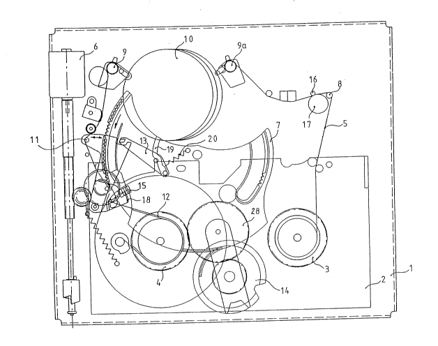
FigO 1 shows a plan view of a tape drive chassis 1 for
a video recorder loaded with a magnetic tape cassette 2.
The magnetic tape 5 is drawn out from the cassette 2 by the
threading motor 6 via the threading elements 8, 9, 9a by
means of guides, which are not illustrated, and arranged
around a head cylinder 10. The capstan motor is located
outside the cassette 2. Its shaft 16 drives, on the one
hand, the magnetic tape 5 in connection with a rubber
capstan idler (RI roll) 17 and, on the other hand, via a
rubber belt which is not illustrated, the set of gears 14
which are engaged with the take-off plate 4 via the tumbler
gear 28 as shown in the Figure. The operating mode 'search
backwards' is predetermined because the magnetic tape 5 is
driven by the RI roll 17 as shown in the Figure. The tape
H 89/087
- 6 - 20~9~91
tension sensor lever 11 also makes contact with the magnetic
tape 5 in this sort of operation whereby, however, the brake
band 12 controllable through the tape tension sensor lever
11 is lifted off, i.e. it is not in contact with the take-
off plate 4, which represents the take-up plate in this sort
of operation. The catch lever 13, with reference to the
position of the tape tension sensor lever 11, no longer
functions because the tape tension sensor lever 11 is moved
far to the right - if viewed in the direction of the arrow -
in this sort of operation.
In this position the part 18, connected with the tape
tension sensor lever, is immersed in the sensor 15 which is
here formed as a light barrier. The particular position of
the tape tension sensor lever 11 is detected by the sensor
15 and converted into signals which serve for the control
of the effect of a slip coupling integrated within the set
of gears 14 which then serves for the adjustment of the tape
tension in this sort of operation. The coupling is adjusted
via non-illustrated levers from the threading motor 6 to
which the control signals are fed via an evaluation circuit.
An arrangement of the controllable coupling in a planetary
gear as well as the change of direction of the tumbler gear
28 is better described in the not pre-published DE
application 39 35 150.
In the reproduction or recording operations the tumbler
gear 28 is engaged with the take-up plate 3 by the cam disk
7 which can be rotated by the threading ~otor 6 in the
direction of the arrow and the catch lever 13 is, by being
guided in a droove 19, lifted off the cam disk 7 so far that
the catch lever 13 cannot come into contact with the tape
tension sensor lever 11. The tape tension sensor lever 11
is moved further to the left - if viewed in the direction of
the arrowe - in this sort of operation because a relatively
small tape tension occurs.
H 89/087
- 7 - 20698
With the change of direction from the reproduction
operation to the backwar~ search mode a rotation of the cam
disk 7 to reach the final position shown here engages the
tumbler gear 28 with the winding plate 4 and the catch lever
13 is released by the groove 19 so far that the spring 20
forces the catch lever against the oblique-shaped surface of
the tape tension sensor lever 11. Hereby, the last received
position of the tape tension sensor lever 11 is firmly held
during the change of direction process. So, the brake band
12 also maintains the adjusted effect~ The tape tension is
increased first by the starting of the capstan motor and
therewith the driving of the winding plate 4 whereby, the
tape tension sensor lever 11 i5 moved to the right - as
viewed in the direction of the arrow. The catch lever is,
through this process, brought into a state without function
caused by the particular form of the supporting area of the
tape tension sensor lever 11, and the brake band 12 is
lifted off the winding plate 4. The further control of the
tape tension is then taken over by the coupling in the set
of gears 14.
Fig. 2 shows a block circuit diagram for the coupling
adjustment by means of an electro-mechanical converter 6.
The tape tension sensor lever 11 has a specially-formed
part 18 which, for example, can consist of a transparent
foil marked with lines if the sensor 15 is formed as a light
barrier, and this part is immersed in the sensor 15 in the
backward search type of operation. For the case of a sensor
15 formed as a Hall element in order to distinguish a
mechanical position of part 18 relative to a fixed point, as
shown by the arrow in the Figure, then a particular shape
would satisfy, as shown in the Figure. Position signals are
generated by the sensor 15 which are converted into control
signals in an evaluation circuit 21. These serve for the
H 89/087
2 0 6 9 8 ~ 1
follow-up adjustment of an electro-mechanical converter 6.
In this example the converter 6 is the existing threading
motor 6 already provided in the device which is connected
via a lever arrangement with the adjustable slip coupling in
the set of gears 14 and sets the tape tension by adjusting
the slip coupling effect according to setting given by the
sensor 15. The dotted line between the set of gears
~coupling 14) and the part 18 of the tape tension sensor
lever 11 represents the regulation of the tape tension by
means of adjustment of the slip coupling. This sort of
control is a closed regulation loop through which the tape
tension throughout the entire length of the magnetic tape
can be sensitively held at an approximately constant value.
Fig. 3 shows the adjustment of the coupling effect
dependent on the tape winding diameter.
In cassette 2 the rotational speeds of the adjusted
tape winding diameters 25, 26 are detected by means of the
sensors 23 and 24 in a manner already known. These deliver
signals to a microprocessor 22 which calculates the adjusted
tape winding diameters from the rotational speeds and
generates a control voltage from the relati.onship of the
diameters to each other which is fed to the electronic
converter 6 for the purpose of adjusting the coupling effect
of the controllable coupling in the set of gears 14.
H 89/087