Note: Descriptions are shown in the official language in which they were submitted.
~~~~~3~
WO 91/07910 PCT/GB90/01708
FETAL PROBE
This invention relates to obstetrics and in particular to probes
for fetal monitoring.
The monitoring of the fetus is a vital aspect of modern labour
management. Assessment of the fetal heart rate is a mainstay of such
monitoring and can be done externally or by internal electrodes. In
certain circumstances, internal monitoring is preferred and provides a
more accurate representation of the fetal heart rate pattern for
analysis. Internal monitoring probes are usually made of arcuate or
spiral metal needles which perforate the scalp skin and are thus secured
to obtain electrical signals from the fetal heart. Such probes can be
considered invasive to the fetus.
Alternatively, intrauterine probes have been designed which do not
have to perforate the fetal skin and which have contact electrodes that
lie apposed to the surface of the fetal body and scalp. Reference is
directed for example to US-3.326,207 and GB-A-2.195,877. These probes
are long and have several built-in electrodes to ensure that at least
one of them is in sufficient contact with the fetal skin to obtain an
adequate signal. Another sensor, some distance away, is used as a
reference electrode. Unless already ruptured spontaneously, the
membranes r the amniotic sac have to be ruptured artificially before
such a probe is inserted. Because of this aspect and its overall length,
such probes can be considered invasive to the mother and the uterine
environment of the fetus.
The probe disclosed in GB-A-2.195,877 comprises an elongate
flexible strip having a series of protruding electrodes. The strip is of
sufficient length (approximately 50 cm1 to extend past the fetal head
and along the trunk of the fetus. US-3,32fi,207, issued in 1967,
proposed a fetal probe having two inflatable balloons positioned as to
contact the shoulder and hiplthigh regions of the fetus, respectively.
~Oo~~~
W091/07910 PCT/GB90/01708 ''
-2-
Each balloon is spherical and carries six or so equatorially spaced
electrodes. Additionally, each electrode is provided with a port for the
local discharge of a conductive solution. The construction and operation
of this probe is considered to be far too elaborate and cumbersome for
practical application.
It is an object of this invention to provide an improved fetal
probe which is not invasive to the mother or the fetus.
Accordingly, the present invention consists in one aspect in a
fetal probe comprising an elongate body portion adapted for insertion
into the cervix around the presenting part of the fetus, the body
portion carrying fetal sensor means; characterised in that the body
portion is insertable into the cervix to a length of between 10 and 20
cm and preferably about 15 cms enabling positioning of the probe such
that the sensor is held against the fetal presenting part by the
pressure of maternal tissue with the amniotic membrane intact.
The probe according to this invention can be inserted through the
vagina into a cervical opening of 1 cm or more dilatation, with the most
distal part of the probe extending into the lower part of the uterus
only, inside the cervix and just above the presenting part. The amniotic
membranes do not necessarily have to be ruptured to enable this
insertion.
The probe can be a vehicle for a variety of monitoring functions.
and the probe sensor means can take a variety of forms. Principally, the
sensor means would comprise a contact electrode for obtaining the fetal
heart rate signal, using a second, reference electrode positioned on the
maternal surface of the near end of the probe, to be in contact with
vaginal tissues. In addition, the probe can contain the sensors
(photodiode and light emitting diodes (LED'sii for transcutaneous pulse
oximetry. Other sensors can also be built in to measure other
parameters. It has been found that most sensors can detect a
satisfactory signal through intact amniotic membranes.
2~~~~39
WO 91/07910 PCT/GB90/01708
-3-
According to this invention, the probe can be held in place by the
pressure of maternal tissues (cervix, vaginal against the fetal
presenting part; but additionally it can also be secured non-invasively
by an inflatable semi-cuff or balloon at the distal end of the probe.
This balloon can be made of a thin plastic or synthetic-rubber material
and is confined to the maternal surface of the probe. Therefore
inflation will result in the fetal surface of the probe being apposed to
the fetal skin, thus ensuring good contact for the built-in sensors
which are located nearby. The inflated balloon also stops the probe from
slipping out of the cervix and vagina during maternal movement,
contractions and fetal descent, until such time that the fetal
presenting part is delivered or the balloon is deflated for probe
removal. As the balloon is above the presenting part, it does not
interfere with its descent during labour.
Another advantage of the balloon at the distal end of the probe is
that after probe insertion and balloon inflation, gentle traction on the
probe will reliably find a point of optimal contact between the main
sensor area of the probe and the skin of the presenting part.
According to another feature of this invention, there are one or
more channels running the whole length of the probe which can be used
for access into the uterus around the presenting part, without the need
for an additional vaginal examination.
One beneficial use for such an access channel is far rupturing the
amniotic membranes by inserting a special canula to apply localised
suction or contact-glue before rupturing the membranes by traction;
alternatively a small hooked or sharp-tipped flexible trochar can be
inserted to perforate the membranes. Rupturing the membranes in this
area above the presenting part, 1.e. the 'breaking the hindwaters', is
aUeady done occasionally by a special canu(a (brews-Smyth canula) and
can have the following advantages over forewater membrane rupture:
WO 91/07910 ~ ~ ~ ~ ~ a ~ PCT/GB90/01708 ~. T
-4-
1. In cases of poor engagement of the presenting part, hindwater
rupture reduces the possibility of prolapse of the umbilical
cord. This is the main indication for using a Drews-Smyth
canula in clinical practice today. but these canulas are now
rarely used because their rigid, curved shape have
occasionally caused injury; it is suggested that the pliable,
flexible probe of the present invention would make this
procedure more safe.
2. In cases of good engagement of the presenting part, the
membranes may be tightly applied to the skin 4usually scalpl
of the baby and a conventional amniotomy hook may scratch the
skin surface as the membranes are being ruptured. Sometimes,
no amniotic fluid is obtained and there is uncertainty as to
whether the membranes are still intact. These problems are
avoided by rupture of the membranes above the presenting part
where there is more amniotic fluid.
The access channel can then be left open to allow amniotic fluid to
escape even when the presenting part would otherwise, due to a tight
fit, be sealing the pelvic outlet; thus the presence of meconium would
still be noted on inspection.
Another possible use for such an access channel is the insertion of
an intrauterine pressure catheter or transducer. When, during labour, it
becomes apparent that such a catheter needs to be inserted for pressure
monitoring, an often distressing additional vaginal examination for this
insertion can be avoided and the already in-situ probe of the present
invention can be used to guide the tip of the catheter through it and
around the presenting part up into the uterus. The additional cost of
using a long pressure catheter is reserved for those cases where it
becomes actually necessary as labour progresses, while the discomfort of
an extra, intracervical digital examination is avoided. By taping the
proximal ends of the pressure catheter and the probe of the present
invention together, the balloon which is securing the probe in place
also ensures that the pressure catheter does not slip out due to
maternal movement or accidental pulling by an attendant.
CA 02069939 2003-07-14
~a
As embodied and broadly described herE=izx, the i~lvention pz°ovides a
fetal probe
comprising: a single elongate body pcirtion having a fetal sensor mounted
thereon, the
body portion being insertable into a cervix and above' a presenting part of a
fetus
whereby the fetal sensor is positioned between the fetus and a maternal tissue
during a
cervical dilation. 'hhe f:efial probe coxzaprise;s an expandable means on a
distal end of
the body portion for urging the sensor into ~rzgag~:zx ent with tlae fetus and
having a
collapsed state to facilitate insertion cat' the body portion into tl-re
cervix azid above the
presenting part of the fetes and arz expanded state fc:rr urging the fetal
sensor into close
engagement with the fetus. The expaxxdable means in its expanded state defines
a
surface having a portion displaced fx~ozxl the distal end c>f the body portion
to wedge
the fetal probe between the fetus and the maternal tissue such that said fetal
probe is
secured against :removal without returning the e:xpaz:zdable means to its
unexpended
state and the sensor is urged into closer engagement with the fetus, tlxe
sensor also
being urged into clos~ez~ engagement with the fetus and the nxaterrxal tissue
by
I S intrauterine pressure during delivery. 1°he expandable means is
mounted on only the
single elongate body portion.
As embodied and broadly described herein, the iz~zvtntion further provides a
fetal
probe comprising an elongate body portion adapted far insertion into a cervix
around
?0 a presenting part of the fetus, the body pc:>rtioxx conxprisizxg a fetal
sensor and having a
distal end with a location means that is remotely expandable from an
orientation
facilitating insertion of the body portion tc~ a wedgizzg orientation serving
to urge the
sensor into close engagement with the fetus, the wedging orientation being
such that
the sensor is urged into closer engagenxe;axt oz-c slight retr<xctizxg
znovemezzt of the body
25 portion, the location means comprising integral wedging surface urged
outwardly on
relative longitudinal movement between t:he body portion and an elongate,
parallel
expander passing through the body portion.
2~~~~~~
WO 91/07910 PCT/GB90/01708
-5-
The present invention will now be described by v~ay of example with
reference to the accompanying drawings, in which:- .
Figure 1 is a plan view of a fetal probe according to this
invention;
Figure 2 is a side view of the probe shown in Figure 1;
Figures 3, 4 and 5 are enlarged scale sections on respectively
lines 3-3, 4-4 and 5-5 of Figure 2;
Figure 6 is a diagrammatic representation of the probe of Figure 1
when positioned in the uterus;
Figure 7 is a part sectional view through the end of a fetal probe
according to a further embodiment of this invention; and
Figure 8 is a sketch showing a different orientation of the probe
end shown in Figure 7.
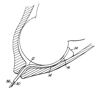
Referring initially to Figures 1 and 2, the probe 10 comprises a
strip like body portion 12. This carries on one surface a maternal
reference electrode 14 and, on the opposite surface and towards the
distal end of the probe, fetal sensor means 16. In this example, the
sensor means 16 takes the form of an ECG electrode 18, a photodiode 20
and a photosensor 22. In known fashion, the photodiode 20 and
photosensor 22 can be used to determine the oxygenation levels of fetal
blood. At the distal end of the body portion 12 is formed an inflatable
balloon or sac 24. Thls sac is of, generally hemi-spherical shape.
As seen more clearly in Figures 3, 4 and 5, a lozenge shaped
channel 26 extends through the length of the body~pc~ cion 12. The
purpose of this channel 26 will be described in more detail later. A
bore 28 in the probe body communicates between the inflatable sac 24 and
a coupling 30 at the proximal end of the body portion. A syringe or
other suitable means for inflating the sac 24 can in use be connected
2~~~93~
WO 91 /07910 PCI~/GB90/01708
-6-
with this coupling 30. Passages 32 and 34 carry leads communicating
between the external lead 36 and, respectively, the photodiode 20 and
photosensor 22. Passage 38 similarly carries a lead connecting with the
fetal electrode 18.
The intended manner of use of the described fetal probe can best be
understood with reference to Figure 6. The probe, with the sac 24
deflated, is introduced through the cervix passing between the
presenting part of the fetus (which will usually be the fetal head) and
the opposing uterine wall. When the probe has been inserted to a length
of approximately 15 cm, the sac 24 is inflated. This will typically be
achieved by the use of a syringe connected with the coupling 30. Slight
tension applied to the probe by the attendant will then ensure that the
sensor is securely held against the fetal scalp with the inflated sac 24
wedged between the maternal tissues and the fetal head. It will be
recognised that this wedging action will maintain the position of the
fetal sensor even in the face of contraction or other maternal or fetal
movements. Indeed, the probe should remain in position even if the
parturient were to stand up and walk during labour.
With the sac 24 positioned to the maternal side of the probe 'body
portion 12, and because of the shape of the sac being generally convex
to the maternal tissues and flat toward the body portion, the effect is
to urge the body portion and thus the fetal sensor into still closer
contact with the fetal skin.
Because the probe according to this invention extends only'a
relatively short distance into the uterus, as compared for example with
that disclosed in G8-A-2195897, it is not necessary for the amniotic
membrane to be deliberately ruptured. Moreover, it is to be expected
that proper usage of the probe according to this invention will
generally not lead to rupture of the membrane. The avoidance of
premature rupture of the amniotic membrane offers clinical advantages.
By this criterion, the preferred insertable length of the probe body is
from 10 to 20 cm and advantageously about 15 cm.
WO 91/07910 PCT/GB90/01708
The channel 26 can be used, with the probe positioned as shown in
Figure 6, to pass appropriate instruments into the uterine cavity in a
straightforward manner and with minimum discomfort to the parturient.
The examples have already been quoted of the insertion of appropriate
instruments for amniotomy, drainage of amniotic fluid and passage of an
intrauterine pressure catheter.
Because of the nature of the probe and its sensor, it will not be
harmful to the fetus and satisfactory signals will usually still be
achieved whether the sensor is positioned on the fetal scalp or on the
face or ears of the fetus.
The use of a generally flat body portion enables the correct
opposition of the fetal and maternal electrodes respectively. An
alternative tubular arrangement would be possible, however, which did
not require insertion in a particular orientation. In that case, pairs
of fetal electrodes (for example) and maternal electrodes would be
provided at opposite sides of the probe. Signals would be taken from
both electrodes of each pair and the associated circuitry would be
arranged to select the fetal or maternal signals as appropriate.
In a modification (which is not shown in the drawings) the
described hemi-spherical sac is replaced by a spherical sac positioned
between two flat leaves formed integrally with the probe. Conveniently,
the fetal sensor can be provided on one leaf and the maternal electrode
on the other. During insertion of the probe the two leaves lie flat
together, with the free end of one leaf being held for example in a
small overhang at the end of the opposing leaf. By inflation of the sac,
the two leaves can be forced apart to provide the desired wedging
action.
~O~J~3~
WO 91 /07910 PCT/GB90/01708
.g.
Whilst the described inflatable sac or balloon represents the
preferred arrangement, there are a variety of further location means
which can be expanded remotely to serve the same wedging function. One
such alternative location means will now be described with reference to
Figure 7 and 8. Figure 7 shows the distal end of a tubular probe body
portion 50. The tubular wall is bifurcated to form two hemi-cylindrical
wall sections 52. The thickness of these wall sections 52 is
significantly less than the wall thickness in the remainder of the body
portion as shown for example at 54. The shoulder 56 between the wall
sections 52 and 54 serves to define a hinge region about which the wall
sections 52 can be splayed outwardly.
An expander 58 has a hollow stem 60 extending through the length of
the body portion 50 and projects from the proximal end (not shown) of
the probe to enable manipulation by the attendant. At the distal. end,
the expander 58 has an integral conical section 62 with a rounded
forward surface 64. A bore 66 extends through the length of the
expander 58 for the subsequent insertion of, for example, a trocular.
The probe is inserted through the cervix in the orientation shown
in Figure 7. The rounded surface 64 facilitates entry of the probe and
the wall sections 52 are held tightly closed through inherent
resilience. Once the body portion 50 has been inserted to the
appropriate length, the expander 60 is withdrawn relatively to the body
portion 50. The effect of this relative motion, as depicted in Figure 8
is to force the hemi-cylindrical wall sections 52 outwardly. In a manner
analogous with the inflation of the previously described inflatable sac,
this expansion of the distal end of the probe enables a wedging action
between the presenting part of the fetus and the opposing maternal
tissues.
Still other arrangements will occur to the skilled man in which
integral wedging surfaces are urged outwardly on relative longitudinal
movement between the body portion and an elongate, parallel expander
passing through the body portion.
20~~~~
WO 91/07910 PCT/G890/0170$
_g_
In appropriate circumstances, the fetal sensor may be held
sufficiently firmly against the presenting part of the fetus without the
need for additional locating means. This invention accordingly
encompasses within its scope the use of a fetal probe which can be
inserted between the presenting part of the fetus and the opposing
maternal tissue without rupture of the amniotic membrane. In this form
of the invention, the described access channel through the probe body
remains of importance.