Note: Descriptions are shown in the official language in which they were submitted.
207011S
_
AQ-1054 - 1 -
DESCRIPTION
FLEXIBLE CONNECTOR
TECHNICAL FIELD
The present invention relates to the field of connectors for
fastening together lengths of tubing and, more particularly, relates to
a spherical ball-type connector capable of accommodating large
angular bending and twisting motions having a seal highly resistant
to leakage and means for damping vibration and noise.
BACKGROUND ART
The following patents have been considered in the preparation
of this application: U.S. Patent Nos. 2,154,077; 2,~36,436;
3,680,895; 4,068,868; 4,480,857; 4,606,559; 4,706,998;
4,906,027; and 5,048,873.
Fluid transport systems utilizing rigid lengths of tubing such as
copper, steel or aluminum tubing are often subjected to mechanical
vibrations which, if not absorbed or dampened may cause tubing
failure due to metal fatigue, failure of the seal and may produce
undesirable noise. This is particularly true in fluid transport systems
used in automobiles and other vehicles.
The present invention provides a flexible connector having a
design which absorbs motion between the connected components
- 2 _ 20701 1~
during operation of the fluid conveying syst , dampens
system noise and vibration and allows for ease of
installation despite some misalignment between adjacent
ends to be connected. O-ring seals are incorporated into
a guide/thrust ring assembly to provide a seal against
leakage of the fluid flowing therethrough while permitting
angular movement as well as twisting or rotational movement
between adjacent lengths of tubing. Noise and vibration
damping are achieved through an elastomeric pad of non-
uniform thickness bonded between a spherical shell andanother internal shell.
Accordingly, it is an object of the present
invention to provide a flexible connector for tubing of the
type used in fluid conveying systems for automotive and
other use which permits angular bending and twisting
motions between the adjacent lengths of tubing and does so
in a manner which dampens noise and vibration.
It is another object of the present invention to
provide a flexible connector which may readily connect
adjacent lengths of tubing notwithstanding the fact that
there is some misalignment of such lengths of tubing.
Accordingly, the present invention provides a
connector for sealingly joining together opposing ends of
first and second lengths of rigid tubing comprising:
(a) an inner shell having a first section
exten~ing from said first length along an axis and a
bulbous section ext~n~ing outwardly to a radial extent
greater than said first section, said bulbous section
terminating in an open end;
(b) a spherical shell encircling said bulbous
section and cooperating therewith to define a space, the
breadth of that portion of said space adjacent said open
end being greater than the breadth of said space at the
other end of said spherical shell, said spherical shell
having an outer surface defining a segment of a sphere;
(c) elastomeric pad means in said space adhered
to said spherical shell and to said bulbous section,said
elastomeric pad means extending from a relatively thicker
'. ~
- 2a - 20701 1 5
portion adjacent said open end to a thinner portion
adjacent said other end;
(d) an outer shell having a first section
extending from said second length, an outwardly flaring
wall section and a housing section having an inner surface
sized to receive therein said spherical shell in spaced
relationship thereto;
(e) a plurality of spaced apart circumferential
bearings in the space between said spherical shell outer
surface and said housing inner surface, each of said
bearings having a first surface engaged to said housing
inner surface and a second surface engaged to said
spherical shell outer surface;
(f) at least one gasket means between said
bearings in the space between and sealingly engaged to said
spherical shell outer surface and said housing inner
surface; and,
(g) flange means for retaining said bonded inner
shell bulbous section and said spherical shell within said
outer shell housing section.
The present invention further provides a
connector for joining together an end of a first length of
tubing and an end of a second length of tubing comprising:
(a) a bulbous end portion on said first length
having a passageway exten~ing therethrough and terminating
in an open end;
(b) a spherical shell having a spherical
exterior surface of predetermined diameter encircling said
bulbous end portion in spaced relationship defining a gap,
the size of said gap being greater at said open end than at
other portions of said bulbous end portion;
(c) pad means positioned in said gap adhered to
said spherical shell and to said bulbous end portion said
pad means extending from a relatively thicker portion
adjacent said open end to a thinner portion spaced from
said open end;
(d) an enlarged receiving end on said second
length, said enlarged receiving end including a segment
., .
20701 1 ~
- 2b -
having a cylindrical interior surface with a diameter
larger than said spherical shell predetermined diameter, an
intermediate section tapering from said enlarged receiving
end to a size smaller than said predetermined diameter,
said bonded spherical shell and bulbous end portion being
received within said enlarged receiving end with a space
between said spherical exterior surface and said
cylindrical interior surface and the interior surface of
said tapering intermediate section;
(e) bearing means in at least two portions of
said space, each of said bearing means having a cylindrical
surface engaged with said cylindrical interior surface and
a spherically ch~pe~ surface engaged to said spherical
exterior surface;
(f) seal means between said bearing means
encircling said spherical exterior surface in sealing
relationship therewith and sealingly engaged with said
cylindrical interior surface; and,
(g) radially inwardly extending flange means
engaged to one of said bearing means.
The invention will be more readily understood
from the following description of a preferred embodiment
thereof given, by way of example, with reference to the
accompanying drawings, in which:
Fig. 1 is a sectional view taken through the
longitudinal axis of the flexible connector of the present
invention;
Fig. 2 is a sectional view similar to Fig. 1
showing another embodiment of the present invention;
Fig. 3 is a view showing by means of a finite
element mesh, deformation of the elastomeric pad portion of
the flexible connector as a result of stresses imparted to
the system due to internal pressure; and
, ,.
2070115
.
AQ-1054 - 3 -
Fig. 4 is a sectional view of a further embodiment of the
present invention.
BEST MODE OF CARRYING OUT INVENTION
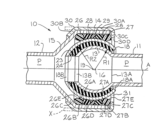
Referring now to Fig. 1, there is shown one form of connector
10 of the present invention for fastening together the end of a first
tength of tubing 11 and the end of a second length of tubing 12. As
shown, the first and second lengths of tubing extend along an axis A
and each of such lengths of tubing 11 and 12 defines a passageway
P for the conveyance of fluid, either liquid or gaseous. It is
contemplated that the flexible connector of the present invention
could be used in an automotive air-conditioning system for conveying
a refrigerant such as freon. However, it will be readily apparent that
many types of fluids, gaseous or liquid, co~lld flow satisfactorily
through the flexible connector system of the present invention.
As can be seen in Fig. 1, the first length of tubing 11 has been
enlarged through processes well-known in the art to form a spherical
enlargement 13 extending from a line of juncture 1 3A with the main
body of the tubing 1 1 to an open end 1 3B. The spherical
enlargement 13 has a radius R1 of predetermined length from a
center point 16 to its outer surface. The second length of tubing 12
is enlarged to a significantly larger extent forming an end section 14
having a cylindrical configuration and an- intermediate section 1~
joining the main portion of the second length of tubing 12 and the
cylindrical end section 14. As shown, the intermediate section 15
has a configuration of a frustum of a cone; however, other
configurations may be used for such intermediate section 15.
Encircling the spherical enlargement 13 of the first length of
tubing 11 is a spherical shell 18 which is a segment of a sphere
having a radius R2 extending from a center 19 to its inner surface.
The radius R2 is larger than the radius R1 of the spherical
207011~
AQ-1054 - 4 -
enlargement 13 so that there is a space between the outer surface of
the spherical enlargement 13 and the inner surface of the spherical
shell 18. The spherical shell 18 extends from a first end 18A to a
second end 18B and is positioned such that its center point 19 is
farther from said line of juncture 13A than is the center point 16. As
a result of the center point 19 being farther from the line of juncture
13A than the distance from the center point 16 of the spherical
enlargement 13 to such line of juncture 13A, the space between the
inner surface of the spherical shell 18 and the outer surface of the
spherical enlàrgement 13 will be of non-uniform thickness and will be
thinner at the end 18A adjacent the line of juncture 13A (i.e., the
right-hand side as shown in Fig.1) and larger at the end 18B adjacent
the open end 13B. If the diameter of the openings at the ends 18A
and 18B are smaller than the outside diameter of the spherical
enlargement 13, the spherical shell 18 may be positioned over the
end of the length of tubing 11 prior to forming the spherical
enlargement. With the spherical shell 18 so positioned, the spherical
enlargement 13 may then be formed using procedures well known in
the art.
Positioned within the space between the outer surface of the
spherical enlargement 13 and the inner surface of the spherical shell
18 is an elastomeric pad 23 of non-uniform thickness. Depending
upon the type of elastomeric material used for the pad 23, it may be
desirable to provide a second elastomeric pad 24 utilizing a second
type of elastomeric material specifically tailored to act as a barrier to
resist permeation and degradation from the fluid intended to flow
through the passageway P of the joined first length of tubing 11 and
second length of tubing 12. For example, the first elastomeric pad 23
could be formed of a suitable plastic or a rubber-like material such as
SBR synthetic rubber, natural rubber, neoprene or a urethane material.
A suitable elastomeric material is one sold under the name Tornac~
- 2070115
AQ-1054 - 5 -
manufactured by Polysar, Sarnia, Ontario, Canada. The second layer
of elastomeric material 24 may be a material marketed under the
name SelarOH by DuPont Chemical, Wilmington, Delaware, if the fluid
flowing through the passageway P is a refrigerant such as Freon~;
however, other materials may be utilized depending upon the
characteristics of such intended fluid. If the material from which the
first elastomeric pad 23 had sufficient resistance to permeation and
degradation of the fluid passing through ~he passageway P, only a
single elastomeric pad 23 is necessary.
~ The elastomeric pads 23, 24, are bonded to the outer surface
of the spherical enlargement 13 and to the inner surface of the
spherical shell 18. This may be accomplished by assembling the
spherical shell 18 around the spherical enlargement 13 and injecting
heated and plasticized elastomeric material into the space to form the
elastomeric pad 23. In lieu of injecting plasticized elastomeric
material into the space, a preformed pad of elastomeric material may
be positioned in such space and adhered to the outer surface of the
spherical enlargement 13 and the inner surface of the spherical shell
18. If it is desired to utilize a different elastomeric material for the
second elastomeric pad 24, a second injection molding step may be
utilized to force such second elastomeric material in position. An
adhesive rnay be used to insure a good bond between the elastomeric
pads 23 and 24 and the outer surface of the spherical enlargement
13 on one side and the inner surface of the spherical shell 18 on the
other side. One such adhesive is one marketed under the name
ChemLok~ 205/220 by Lord Corporation, Erie, PA.
The outer diameter of the spherical shell 18 taken through a
plane perpendicular to the axis A is smaller than the inner diameter of
the cylindrical end section 14 with the result that the spherical shell
18 is in spaced relationship with the inner surface of the cylindrical
end section 14.
2070115
.
AQ-1054 - 6-
Positioned within such space are a pair of circumferential nylon
bearings 26 and 27 which function as bearings supporting, within the
cylindrical end section 14, the assembly consisting of the spherical
enlargement 13, the pads 23, 24, and the spherical shell 18. The
bearing 26 adjacent the open end 13B of the spherical enlargement
13 includes a first surface 26A contoured with a spherical shape
conforming to and engaging the outer spherical surface of the
spherical shell 18 and a generally opposing surface 26B having a
generally cylindrical configuration conforming to that of the interior
surface of the cylindrical end section 14. The bearing 26 is also
shown as having a forward surface 26C, a trailing surface 26D and
an interior surface 26E extending between the spherical surface 26A
and the forward surface 26C.
Similarly, the bearing 27 has a first surface 27A contoured with
a spherical-shape conforming to and engaging the outer spherical
surface of the spherical shell 18, a cylindrical surface 27B contoured
to conform with and engage the interior surface of the cylindrical end
section 14, a trailing surface 27C, a forward surface 27D and an
interior surface 27E joining the spherical surface 27A with the trailing
surface 27C. The bearings 26 and 27 are preferably formed of nylon
but may be formed of other materials possessing chemical resistance
to the fluid being conveyed and sufficient strength to support the
members in sealed position while permitting rotational and pivotal
movement between the first length of tubing 11 and the second
length of tubing 12. Other suitable materials include various metals,
ceramics and other thermoplastics.
Positioned between the bearings 26 and 27 are a pair of O-ring
seals 28 which are spaced apart with a nylon or other suitable
material circumferential spacer 29 positioned therebetween. Other
seals having different configurations may be used in lieu of O-rings.
The O-ring seals 28 are preferably formed of a resilient, chemically
`-- 2070115
AQ-1054 - 7 -
stable polymeric material such as a flourosilicone polymer known as
Neoprene W. Depending upon the fluid being conveyed, other types
of materials may be used for the 0-ring seais 28 and for the
circumferential spacer 29. The 0-ring seals 28 are compressed
between and form a liquid and vapor tight seal between the outer
spherical surface of the spherical shell 18 and the interior surface of
the cylindrical end section 14. The 0-ring seals 28 may also contact
the adjacent bearing 26 or 27 and the spacer 29; however, such
contact is not required for a liquid and vapor tight seal.
A collar 30 is provided to secure together the assembly
consisting of the spherical enlargement 13, the pads 23, and the
spherical shell 18 within the cylindrical end section 14, with the
bearings 26 and 27, 0-ring seals 28 and spacer 29 therebetween.
The collar 30 has a central cylindrical section 30A sized to snugly
1 ~ engage the outer surface of the enlarged cylindrical end section 14 of
the second length of tubing 12 and a tapered end section 30B
tapering inwardly to a position to engage the intermediate section 15
of such second length of tubing 12. The end of the collar 30 forming
the tapered end section 30B initially is cylindrical and extends beyond
cylindrical end section 14 as shown in dashed lines labelled X in Fig.
1. After the respective components are joined to the position shown
in Fig. 1 but with the cylindrical section 30A of the collar 30
extending longitudinally beyond the cylindrical end section 14 to the
position X illustrated in dashed lines, such end portion is deformed to
form the tapered end section 30~ which snugly engages the tapered
intermediate section 15. As can be seen in Fig.1, such deforming of
the collar 30 to form the tapered end section 30B causes flange 30C
to firmly engage the bearings 26 and 27 within the space between
the spherical shell 18 and the interior surface of the cylindrical end
section 14, with the forward surface 26C of bearing 26 being held in
place by the juncture of the intermediate section 15 of the second
AQ-1054 - 8 - 2070115
length of tubing 12 with the cylindrical end section 14. If desired,
the tapered end section 30B could be preformed in which case the
other end forming the flange 30C would initially be a cylindrical
extension of cylindrical section 30A and deformed during assembly
to form such flange 30C.
As may be appreciated from viewing Fig. 1, the portion of the
spherical shell 18 aligned with the spacer 29 may be considered as
the apex which is closer to the inner surface of the cylindrical end
section 14 than other portions of such spherical shell 18 and the
bearings 26 and 27 are positioned on opposite sides of such apex,
thus securing in place the assembly of the spherical shell 18, pads 23
and 24 and spherical enlargement 13 of the first length of tubing 11
while permitting pivotal and rotational movement between such
assembly and the second length of tubing 12.
As can be readily seen in Fig. 1, the flange 30C of the collar 30
terminates at an end 30D which is radially spaced from the spherical
shell 18, thus leaving a gap 31 between such flange end 30D and the
outer surface of the spherical shell 18. The presence of the gap 31
coupled with the spherical configuration of the outer surface of the
spherical shell 18 slideably engaged to the spherical surfaces 26A and
27A of the bearings 26 and 27, respectively, permits the spherical
shell 18 and the first length of tubing 11 bonded thereto by the pads
23 and 24 to move pivotally within the cylindrical end section 14 of
the second length of tubing 12. Additionally, as will be appreciated,
such construction also permits the spherical shell 18 and such first
length of tubing 11 bonded thereto to be moved rotationally relative
to the second length of tubing 12.
If desired, the outer surface of the spherical shell 18 may be
provided with a Teflon~ coating which will serve to reduce the
frictional wear on the bearings 26 and 27 and the seals 28 thereby
2070115
AQ-1054 - 9 - -
increasing their useful life. Other friction reducing coatings may be
used in lieu of the Teflon~ coating.
As previously discussed, the space between the outer surface
of the spherical enlargement 13 and the inner surface of the spherical
shell 18 and, therefore, the elastomeric pad 23 which is bonded
therebetween is of non-uniform thickness. Thus, the thickness of the
elastomeric pad 23 adjacent the open end 13B of the spherical
enlargement 13 is significantly thicker than the portion of the
elastomeric pad 23 adjacent the line of juncture 13A of the spherical
enlargement 13. The non-unifoFm tllickness of the pad 23 is a critical
and significant feature of the present invention and it should always
be thicker at the end adjacent the open end 13B.
As will become clear from a description of the embodiments of
Figs. 2 and 4, it is not necessary that the enlarged end of the first
length of tubing 11 have a spherical configuration. Rather, such first
length of tubing 11 could have an enlargement with any of a wide
variety of configurations. However, it is important that the outer
surface of the spherical shell 18 have a spherical configuration in
order to permit it to move angularly and rotationally with respect to
the cylindrical end section 14 and the bearings 26 and 27.
Under the embodiment of Fig. 2, there is provided a first length
of tubing 32 having an enlargement 33 which may have any of a
wide variety of configurations including but not limited to ellipsoidal
and ones having in cross section parallel to the axis A, a parabolic or
other curvilinear path. The enlargement 33 extends from a line of
juncture 33A with the main body of tubing 32 to an open end 33B.
There is also provided a spherical shell 35 encircling the
enlargement 33 in spaced relationship such that the space between
the inner surface of the spherical shell 35 and the outer surface of the
enlargement 33 is larger at the end 35B adjacent the open end 33B
than at the end 35A adjacent the line of juncture 33A. Positioned
~ 2070115
AQ- 1054 ~ 0 -
within such space is a single elastomeric pad 36 of non-uniform
thickness which is thicker at the end 36B adjacent the open end 33B
than the end 36A adjacent the line of juncture 33A. The pad 36 is
bonded to the outer surface of the enlargement 33 and the inner
surface of the spherical shell 35.
There is also provided a second length of tubing 42 havin~ an
enlarged cylindrical end section 44 joined to the main tubing portion
42 by an outwardly tapering intermediate section 43. The cylindrical
end section 44 and intermediate section 43 encircle the assembly of
the spherical shell 35, pad 36 and enlargement 33 in spaced
relationship with the outer surface of the spherical shell 35.
Positioned within the space between the spherical shell 35 and
cylindrical end section 44 are a pair of 0-ring seals 28, a
circumferential spacer 29 and a pair of universal bearings 45. In
contrast to the embodiment of Fig. 1 which utilized bearings 26 and
27 having non-symrnetric cross-sectional shapes, the universal
bearings 45 used in this embodiment are identical to one another and;
therefore, do not require the care in assembly required for the Fig. 1
embodiment.
A flange 46 extends radially inwardly from cylindrical end
section 44 and engages the adjacent universal bearing 45. The other
universal bearing 45 is engaged by the interior surfaces of the
intermediate section 43 and the cylindrical end section 44.
Each of the universal bearings 45 includes an exterior surface
47 following a generally U-shaped configuration with the legs of the
U tapering outwardly and a pair identical interior surfaces 48 which
follow a spherical configuration similar to that of the outer surface of
the spherical shell 35. As an optional feature, there may be provided
a radially inwardly extending lip 49 extending from the respective
interior surfaces 48 and Iying on a plane extending centrally through
the bearing 45. Upon joining the various elements of the connector
2070115
AQ-1054 - 11 -
together, the lip 49 of each of the universal bearings 45 will, under
pressure, be bent or folded over to act as a dust wiper as it moves
against the exterior surface of the spherical shell 35 upon movement
of it and the first length of tubing 32 relative to the second length of
tubing 42.
The embodiment of Fig. 2 is less expensive than the
embodiment of Fig. 1 in that it does not utilize a collar. The
modification of the flexible connector of the present invention shown
in Fig. 2 is particularly well-suited for joining together lengths of
tubing which are subjected to lower internal pressure, for example,
something on the order of less than 230 psi. Thus, while the
embodiment shown in Fig. 1 utilizing the collar 30 for securing the
various members together may be used for systems which operate
under pressure in excess of 230 psi and as high as 500 psi or even
higher, the embodiment of Fig. 2is less expensive and is satisfactory
for lower pressure applications.
For some applications, including ones subjected to low internal
pressures, it is possible to have only a single 0-ring seal 28 in which
case it will not be necessary to have a spacer 29. Such modified
connector would have at least two bearings 26, 27 or 45, 45 with
one 0-ring seal 28 positioned therebetween in seaiing engagement
with the outer surface of the spherical shell 18 or 35 in the area of
the apex and the interior surface of the cylindrical end section 14 or
44.
Referring now to Fig. 3, there is ~shown a finite element mesh
which demonstrates the effect on the elastomeric pad 36 of the
embodiment of Fig. 2 due to internal pressure within the joined
lengths of tubing 32 and 42. As will be appreciated, such internal
pressure results in movement of the first length 32 axially relative to
the second length 42. Such analysis shows why it is necessary that
the elastomeric pad 36 be of non-uniform thickness with the thicker
- 2070115
AQ-1054 - 12-
end 36B adjacent the open end 33B of the enlargement 33 and the
thinner end 36A spaced away from such open end 33~.
The elastomeric pad 36, although possessing significant
resistance to compressive stresses is much less resistant to tensile
stresses. As will be appreciated and as can be seen schematically in
Fig. 3, the application of internal pressure within the passageway of
the first and second lengths of tubing 32 and 42 will cause the first
length 32 having the enlargement 33, to be moved a slight distance
axially, thus, tending to pull away from the second length of tubing
42. However, the enlargement 33 and the spherical shell 35 with the
elastomeric pad 36 bonded thereto are prevented from such axial
movement as a result of the bearings 4~ which are firmly held in
place as previously described engaging the outer surface of the
enlargement 33. As a result, the portion of the pad 36 toward the
end 36A is subjected to compressive stresses and bulges outwardly
in response to such compressive stresses.
In contrast, the portions of the pad 36 adjacent the end 36B
are placed in tension as a result of the increased distance between
the open end 33B of the enlargement 33 and the end 35B of the
spherical shell 35 upon such axial movement of the first length of
tubing 32.
In Fig. 3 there is shown schematically only those portions of
the flexible connector required to illustrate the stress analysis,
namely, first length of tubing 32, its enlargement 33, the spherical
section 35 and the non-uniform thickness pad 36. Each of the first
length of tubing 32, its enlargement 33 and the pad 36 are shown
with two sets of mesh lines, the first being dashed lines showing the
positions of those respective members before the application of
internal pressure within the passageway and the second being solid
lines showing, for each such mesh line portion, the movement of that
portion in response to internal pressure within the passageway of 500
;- 2070115
AQ-1054 - 13-
psi. The spherical shell 35 has only a single set of lines as it is
prevented from moving axially.
It can be readily seen from Fig. 3 that the end 36A of the pad
36 is being squeezed outwardly to the right as a result of the extreme
compressive forces placed upon it by movement of the first length of
tubing 32 and its enlargement 33 to the right, thereby reducing the
size of the space for the pad 36. In contrast, that portion of the pad
36 adjacent the end 36B is subjected to a tensile stress as a result of
movement of those portions of the two elements to which it is
bonded, namely, the interior surface of the spherical shell 35 and the
exterior surface of the enlargement 33, away from one another.
Thus, the respective portions of the pad 36 illustrated by the mesh
lines are caused to move from the positions illustrated by the dashed
lines to the positions in solid lines. As result of such non-uniform
thickness of the pad 36, the connector of the present invention is
permitted to function satisfactorily without breaking the bonds
between the pad 36 and ( 1 ) the outer surface of the enlargement 33
and (2) the inner surface of the spherical shell 35. Such design
imparts high compressive stresses in the thin end of the pad 36A and
significantly lower magnitude tensile stresses in the thick end 36B.
Under the embodiment of Fig. 4, there is provided a first length
of tubing 51 having an enlargement 53 which may have any of a
wide variety of configurations including but not limited to ellipsoidal
and ones having, in cross section parallel to the axis A a parabolic or
other curvilinear path moving from its line of juncture 53A with the
fixed diameter tubing 51 to the open end 53B.
As in the previous embodiments, there is provided a spherical
shell 55 encircling the enlargement 53 in spaced relationship and
extending from an end 55A adjacent the line of juncture 53A to an
end 55B adjacent the open end 53B. The space between the inner
surface of the spherical shell 55 and the outer surface of the
2070115
.
AQ-1054 - 14 -
enlargement 53 is larger at the end 55B adjacent the open end 53~
than at the end 55A. Positioned within such space is an elastomeric
- pad 56 of non-uniform thickness which is thicker at the end 56Badjacent the open end 53B than at the other end adjacent the line of
juncture 53A. A second pad 57 of elastomeric material specifically
tailored to resist permeation and degradation from the fluid intended
to flow through the passageway may be adhered to the pad 56. The
pads 56, 57, shou1d be bonded to the outer surface of the
enlargement 53 and to the inner surface of the spherical shell 55.
There is also provided a second length of tubing 62 having an
enlarged cylindrical end section 64 joined to the main tubing portion
62 by an outwardly tapering intermediate section 63.
The outer diameter of the spherical shell 55 is smaller than the
inner diameter of the cylindrical end section 64 with the result that
the spherical shell 55 is in spaced relationship with the inner surface
of the cylindrical end section 54. Positioned within such space are a
pair of circumferential nylon bearings 45 which function as bearings
supporting the assembly consisting of the enlargement 53, the pads
56, 57, and spherical shell 58 within the cylindrical end section 64.
Positioned between the bearings 45 are a pair of 0-ring seals
28 which are spaced apart with a nylon circumferential spacer 29
positioned therebetween.
A collar 70 is provided to secure together the assembly
consisting of the enlargement 53, the pads 56, 57, and the spherical
shell 58 within the cylindrical end section 64, with the bearings 45,
0-ring seals 28 and spacer 29 therebetween. The collar 70 has a
central cylindrical section 70A sized to snugly engage the outer
surface of the enlarged cylindrical end section 64 of the second
length of tubing 62 and a tapered end section 70B tapering inwardly
to a position to engage the intermediate section 63 of such second
length of tubing 62. The end of the collar 70 opposite the tapered
207011S
_
AQ-1054 - 15-
end section 70B initially is cylindrical and, after the respective
components are joined to the position shown in Fig. 4 but with the
cylindrical section 70A of the collar 70 extending longitudinally
beyond the trailing surface of bearing 45, such end portion is
deformed to form a radially inwardly directed flange 70C which
snugly engages the trailing surface of bearing 45 thus securing the
assembly of the spherical shell 58, pads 56 and 57 and enlargement
53 in place while permitting pivotal and rotational movement between
such assembly and the second length of tubing 62.
Other modifications will become readily apparent to those
skilled in the art. For example, the connector of the present invention
could be used to connect lengths of rigid tubing formed of plastic as
well as metal or one length formed of plastic to a length formed of
metal. Accordingly, the scope of the present application should be
limited only by the scope of the ap;pended claims.