Note: Descriptions are shown in the official language in which they were submitted.
20702~8
Case 91-176/CH
Switzerland
METHOD AND APPARATUS FOR TESTING CONTAINERS
The invention relates to a method of testing
containers, more particularly glass or plastic bottles,
involving placing a head sealingly onto the mouth of the
container, putting the interior of the container under
pressure by means of a metering piston which can be
displaced in relation to the head, and measuring the
pressure by means of a pressure sensor to check the volume
of the container.
- The invention further relates to an apparatus
for implementing the method, comprising a head adapted to
be moved sealingly onto a mouth of the container, a
metering piston which is displaceable in relation to the
head and can be used to pressurize the interior of the
container, and a pressure sensor for measuring the
` pressure in the interior of the container.
One such apparatus is known in conjunction with
an inspection machine for plastic bottles from
: ~ .
DE 37 22 422 C2. In the case of this known apparatus the
bottle can be clamped on a plate by means of a head
fastened in freely rotatable manner to a vertically
displaceable carriage. The interior of the bottle can be
pressurised through the head, said pressure bein~ recorded
.
, ,'
2~702~
by a pressure sensor disposed on the head. The interior
of the container is pressurised using a metering piston
adapted to be displaceable at right angles to the head in
a cylinder provided inside the carriage. A piston rod
~oined to the metering piston is able to be displaced
against the pressure of a return spring by a cam disc
attached to the machine frame via a follower roller. On
the side of the metering piston nearest the return spring
is a cylinder chamber. Whenever the metering piston is
displaced, the air in this cylinder chamber is forced into
the bottle along a bore provided in the head, and the
pressure sensor records the pressure that builds up inside
the bottle. An electronic analyser compares this pressure -
with a limiting value and subsequently actuates an ejector
in the event of excessive deviation from this limiting
value. A bottle of no~ninal volume has a given limiting
pressure value. If the volume of the bottle is smaller or
greater than the nominal volume, the limiting pressure
value is respectively exceeded or not attained when the
said volume of air is forced in.
The aforesaid inspection machine is primarily
intended for inspecting returnable bottles made from
plastic, ie. bottles returned by the customer and then
,;~
refilled. The known apparatus works perfectly
satisfactorily on this type of inspection machine.
~lowever, it has been shown that problems can arise if the
apparatus is used on an inspection machine employed for
~` series production of PET or glass bottles. Volume
. ~ :
~' .. : ~ " " ': ~, ' :
207~2~8
.
deviations may even occur in this sort of series
manufacturing process. It is therefore necessary to check
the volume of the bottles using an apparatus of the type
indicated initially. If the volume deviations are outside
a given tolerance, the bottles concerned again have to be
identified as defective and removed. In this type of
series production process the bottles, which have usually
: come from a blow moulding machine, contain warmed air.
The volume of air forced into the bottle using the
metering piston is relatively small in comparison to the
volume of the bottle, and the excess pressure produced by
forcing in the volume of air is correspondin~ly small. If
in the series production process the measurement result is
also affected by volumes of air at different temperatures,
; 15 it is no longer possible to obtain reliable readings.
Furthermore, it is in any event no simple matter to
provide an external volume of air that is always constant
' and ideally at the same temperature and force it into a
-~ bottle, for in series production there is usually less
~ 20 than a second available for the entire check per bottle.
.t It has been found that fixing the start of the
~ pressure measurements is a difficult matter. Yet a
- precise starting point for the pressure measurements is
~ indispensable, for as a rule it is necessary in the very
; 25 brief time available for measurement to take a plurality
of pressure measurements under various defined measurement
conditions.
;; It is therefore the object of the invention to
.~`
'
`:
,, , ~ : :
. ,: .- , .. : . .. :: :
- . : ~ . : , . .
.. , ,. ~ , - .
., : : ~ ~,
.: . :
207~9~
simply and reliably fix the starting point for container
testing.
In accordance with the invention this is
achieved by the fact that the pressure sensor records the
pressure gradient when the head is placed onto the
container, and said gradient is used as the signal to
begin the subsequent displacement of the metering piston
and the pressure measurement.
It has been found that by analysing the pressure
gradient when the head is put in place it is possible to
f ix with high accuracy the best starting point for the
measurement cycle that follows. Because the pressure
gradient can be recorded using the pressure sensor which
is in any case provided, the method is simple and
inexpensive to implement.
The testing of the container preferably includes
a leakage measurement in accordance with claim 2.
; The invention further relates to an apparatus
for carrying out the method. Said apparatus comprises a
balancing piston to compensate for dissimilar container
heights, as described below.
In the series production process for PET
bottles, glass bottles and other containers it can happen
that these vary in height. If the plate or conveyor on
which the container is moved under the apparatus is always
at the same height, then should the height of the
containers vary the apparatus in the embodiment according
to claim 3 would give a false reading, for the depth to
'
-: . :-
:: , , : . . .
.,... . , , , , , ::
2~7~298
which the metering piston would penetrate the container
would vary. Whilst it would be conceivable to raise or
lc,wer each container in the apparatus to suit the varying
container height, in order to always start with the
container mouth in the same position, this would entail
considerable constructional costs, which is undesirable in
order not to detract from the simplicity and operational
reliability of the apparatus according to the invention.
In the embodiment of the invention according to
claim 3 it is achieved by using a fixed balancing piston
to compensate for different heights of container whilst
retaining a fixed metering piston drive mechanism and a
fixed base level for the containers. A duct links a
' measured volume inside the container to a compensating
volume inside a compensating chamber. The compensating
volume is determined on the one hand by the constant
; starting position of the metering piston and on the other
hand by length of the displacement path of the head, which
varies according to the particular container height. This
means that the compression ratios are always exactly the
same for different heights of container.
Whilst it is not essential for the balancing
piston and metering piston to be equal in diameter, as in
the case of the embodiment of the invention according to
;`` 25 claim 10, if it were not so conversions would be needed,
or the fixed link between the head and the cylinder would
need to be replaced by a link with a variable transmission
ratio, or the like.
''
.` .~ .
:.-
: , . .:
. .~ . . :.
,: ,
,' `',` ' `' `, ''.~ ; ` ~ , . ` ,: '
207~g
The embodiment of the invention according toclaim 11 is a simple way of linking the interior of the
container to the compensating chamber.
In the embodiment of the invention according to
claims 12 to 14 a pneumatic rotary vane drive ensures a
constant, rapid and damped plunging motion by the metering
piston in a sinusoidal movement.
Because the rotary vane drive is fixed, in the
- embodiment of the invention according to claims 15 and 16
the head is a pneumatically reciprocating piston in a
fixed short-stroke cylinder and hence can always be placed
onto the mouth of the container in a separate sealing
stroke irrespective of the height of the container.
An exemplary embodiment of the invention will
now be described in more detail with reference to the
drawings, wherein:
Fig. l is a sectional side view of an apparatus
according to the invention;
Fig. 2 is a detail from a crank drive used in
the apparatus of Fig. 1, in two different operating
positions;
Fig. 3 is a working diagram of the apparatus
according to Fig. 1, in which a measuring stroke and a
sealing stroke have been performed over the available test
period; and
Fig. 4 is a diagram representing the pressure
gradient at the pressure sensor against time while a
container is being tested~
'`
'
: : ~; : ,.. .
2~7~8
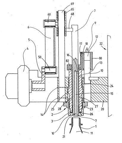
Fig. 1 shows a sectional side view of an
apparatus for checking the volume of containers. As an
example of such a container, a bottle 1 is shown, which
may be made of glass or plastic, preferably PET. The
bottle 1 is moved along a conveyor (not shown) into the
position depicted in Fig. 1 beneath the apparatus and once
its volume has been checked it is moved on, eg. to a
packing or filling station, or alternatively it is removed
if a deviation in volume detected during the check is
outside a given tolerance.
The apparatus is fixed to a carousel or frame 20
of an inspection machine 22. The apparatus has a head,
designated overall by the reference 2, which is arranged
to be vertically displaceable in the frame 20, allowing it
to be moved sealingly onto the mouth 21 of the bottle 1.
Externally the head 2 is in the form of a displaceable
piston 23 reciprocating in a fixed short-stroke cylinder
24. At its lower end the piston 23 carries a nozzle 26,
; in which the mouth 21 of the bottle 1 can be received in a
substantially playfree manner. On its lower end face
inside the nozzle 26 the piston 23 has a seal 3, which
comes to bear on the mouth 21 when the piston 23 is moved
onto the bottle 1. The piston 23 protrudes upwardly and
downwardly from the short-stroke cylinder 24 and is sealed
by unreferenced O-rings on the bearing surfaces of the
cylinder. The arrangement of these O-rings and of
additional O-rings in the apparatus is readily apparent
from Fig. 1 and need not be detailed further here. On its
2~7~8
outer periphery the piston 23 comprises a collar 25 which
divides the interior of the cylinder into upper and lower
cy:Linder chambers. DUcts 14 deliver compressed air
alternately to these cylinder chambers in order to move
the piston 23 up and down.
The metering piston 7 is a cylindrical rod,
which in a starting position illustrated in Fig. 1 is
disposed roughly half in the head 2 and half outside it.
The diameter of the metering piston 7, at least of the
part that is to be inserted into the bottle 1, closely
matches the inside diameter of the mouth 21 of the bottle
1. The piston 23 has a longitudinal bore 28 in which the
metering piston 7 is displaceably accommodated. The
longitudinal bore 28 is sealed in the manner that is
apparent from Fig. 1. To introduce the metering piston 7
into the bottle 1, a drive mechanism 4 is provided in the
form of a pneumatic rotary vane drive connected to a crank
5. The drive mechanism 4 is thus a crank drive and by
means of a crankpin 50 it drives a piston rod 6 joined by
a pivot pin 60 to a slide 65, which in turn is joined by a
pin 68 to the top end of the metering piston 7. The slide
65 is displaceably arranged on a guide 69 parallel to the
metering piston 7.
A cylinder 80 is fixed to the top end of the
~' 25 head 2 through a bracket 82 as illustrated in Fig. 1. The
bracket 82 of the cylinder 80 provides the top closure of
an annular chamber 27 formed in the cylinder 24 between
the wall of the longitudinal bore 28 and the metering
:`
''''',
t,i`~
:
- . : , .
: :
2~7~2~8
piston 7. A fixed balancing piston 13 is at~ached to the
frame 20 by one end. The other end of the balancing
piston 13 projects displaceabl~ into the cylinder 80,
which is open at the bottom, and delimits a compensating
chamber in said cylinder. The volume of the compensating
chamber 12 varies with the downward stroke performed by
the head 2 from the fixed starting position shown in Fig.
1 until it rests on the mouth 21 of the bottle 1.
A duct, designated overall by the reference 10,
links the interior 11 of the bottle 1 to the compensating
chamber 12. The duct 10 consists of a first bore 15 in
the metering piston 7, opening through a first transverse
bore 16 into the annular chamber 27 surrounding the
metering piston in the head 2, and of a second bore 17 and
a second transverse bore 18, by means of which the annular
chamber 27 is linked to the compensating chamber 12. A
sensitive pressure sensor 9 is connected to the
compensating chamber 12.
The mode of operation of the apparatus will now
be described with additional reference to Figs. 2 and 3.
Once there is a bottle 1 in the position beneath
the head 2 depicted in Fig. 1, its pneumatic drive
mechanism lowers the head onto the bottle by the admission
of compressed air through the upper one of the ducts 14
from a compressed air source (not shown). The head 2 is
lowered until the seal 3 seals against the bottle 1 with a
preset pressure. Fig. 3 shows an interval from point to to
tl available for this sealing stroke D. At point tl the
.
. ., ~ , . .
- .
~, , , . ~ ~ . . ' '
' ' . ' ' ' - . . ' . '~
207~2~8
pneumatic drive mechanism 4 of the metering piston 7 is
actuated, in order to initiate a measurement stro]ce M.
The metering piston 7 is now plunged into the bottle by
means of the crank S and the piston rod 6, until the crank
5 has reached bottom dead centre 8 (Fig. 2), at point t~.
The pressure sensor 9 now measures the overpressure
produced in the bottle l (and sends the measurement to an -,
unillustrated analyser), for which an interval from point
t2 to point t, is available. From point t3 the drive
10 mechanism 4 returns the metering piston 7 to its starting
position. At the same time the head 2 is also moved back
to its starting position. In the example illustrated, the
entire possible test period T, ie. the interval between to
and t4, is 0.9 sec. Delays of 0.05 sec shown respectively
15 at the start and end of the stroke in Fig. 3 are system-
dependent.
The measured volume is the volume of the
interior 11 of the bottle l plus the volume of duct 10.
The volume of the compensating chamber 12 linked to the
20 measured volume is determined on the one hand by the fixed
starting height of the metering piston 7 and on the other
hand by the length of the sealing stroke of the head 2.
The compensating volume ensures that the compression
~ ratios are always exactly identical for different bottle
" 25 heights. This is because different bottle heights are
compensated by the balancing piston 13, which is inserted
in the opposite direction into the cylinder 80 and keeps
the compressed measured volume always exactly constant.
:. : . ~ - ,,. , ., :
- - .:
207~2~8
Fig. 4 shows the pressure gradient at the
; pressure sensor over time. The pressure rise and pressure
fa:Ll are clearly visible in the 160 ms time range which
fo:Llows the placing of the head onto the container. This
; 5 pressure gradient is recognised by the analyser circuit
for the sensor output signals and as the starting point
for the following measurement cycle (measurements in the
range pdl, pdi, pdll and pdOl). The leading edge, the
peak or the trailing edge of the pressure increase may be
;10 used. The volume of the container can be determined from
the pressure levels measured.
The two pressure measurements in the pdl and
pdll ranges are preferably also used to detect the
presence of a leak in the container. The diameter of the
leak is proportlonal to the size of the pdl-pdll constant.
'~
.
:
''''
!~
` , ' ' :
'' , ~ : `