Note: Descriptions are shown in the official language in which they were submitted.
f7atent 13DV-tU547
COMBUSTOR DOME ASSEMBLY
Technical Field
The present invention relates generally to gas turbine engine combustors, and,
more
specifically, to an improved dome assembly having means for starting film
cooling of a liner of
the combustor.
Background Art
A typical aircraft gas turbine engine combustor includes annular, radially
spaced apart
outer and inner combustion liners disposed coaxialiy about a longitudinal
centerline axis to
define an annular combustion zone therebetween. Disposed at the upstream ends
of the liners
Is an annular combustor dome fixedly joined thereto and including a plurality
of circumferentlaliy
spaced carburetors therein for providing a fuel/air mixture into the combustor
which is ignited
for generating combustion gases therein.
In order to protect the combustor Pram the hot combustion gases and provide a
useful
service life thereof, various means ace used for Gaoling the dome and the
liners including far
example means for generating boundary layer films of cooling air along the
inner surfaces of the
combustor. Such film cooling must be provided from the dome and extend
downstream along
the full axial extent of the liners. The cooling air film is typically formed
by a circumferentially
extending conventional cooling nugget in the farm of an annular plenum having
a lip defining
an annular outlet slot for discharging the Goosing air film. The nugget
includes a plurality of
circumferentially spaced inlet holes typically located at a radius or apex of
the nugget at an
upstream end of the plenum. In conventional combustors, a plurality of axially
spaced raves of
the cooling nuggets are typically used for ensuring the continuation of an
effective cooling air
film along the entire axial and circumierential extent of the combustor
liners.
Another type of combustor utilizes axially spaced rows of circumferentialiy
spaced
inclined multiholes for convectively cooling the liners as wail as for
providing the cooling a(r film
along the inner surfaces thereof instead of using the conventional nuggets.
However, in some
multihole designs, the multtholes by themselves are unable to start an
effective film of cooling
air, and a conventional nugget or other means is provided for starting the
cooling air film at the
upstream end of the combustor immediately upstream of the first row of
muitihales. An effective
cooling air film Ir such an embodiment must be provided from the dom~ region
of the
combustor to ensure that the multiholes provide an effective cooling air film
wfth an acceptable
heat transfer rate. For example, one m~el test performed on behalf of the
present assignee
shows that the cooling effectiveness of a multihofe liner alone as Compared to
a multihole liner
~, ~atent 13DV-10547
-2-
having a cooling film starting slot at the upstream end thereof has Initially
about 1096 of the
cooling effectiveness compared thereto at the dome end of the combustor. The
cooling
effectiveness of the multihole-only liner increases along the liner in the
downstream direction
whereas the cooling effectiveness of the multihole liner with the cooling air
film starting slot
decreases in the downstream direction, with the film effectiveness of the
latter being substantiaiiy
greater than that of the former up to the last row of the multiholes in the
liner.
The air used for providing a cooling air film in a combustor is a portion of
compressor
discharge air which necessarily decreases overall performance efficiency of
tha combustor since
such air is not being directly used to support the combustion process.
Furthermore, various
conventional cooling air apertures exist in conventional combustors for
providing cooling thereof
including film cooling. Such various conventional structures have varying
degrees of complexity,
cost, undesirable weight, or stress concentrations, or efficiency of use of
the available cooling
air. For example, locating a cooling air aperture in the apex or radius of a
plate typically results
In a substantial stress concentration which must be accommodated, for example
by increased
thickness of the plate, for providing a useful life for the combustor.
Furthermore, since
combustor cooling air typically does not directly support the combustion
process, the use
thereof should be kept to a minimum to avoid overall performance efficiency
losses of the
combustor.
Obiects of the Invention
Accordingly, one object of the present invention is to provide a new and
improved
combustor dome assembly for a gas turbine engine.
Another object of the present invention is to provide a combustor dome
assembly which
more efficiently uses cooling air for increasing combustor efficiency.
Another object of the present invention is to provide a simpler and lighter
combustor
dome assembly.
Another object of the present invention is to provide a combustor dome
assembly having
new means for starting film cooling for a multihole combustor liner.
Disclosure of Invention
A combustor dome assembly includes an annular support plate fixedly joined to
a
combustion liner which confines combustion gases. The support plate Includes a
plurality of
circumferentially spaced support openings for supporting respective
carburetors, and respective
splashpiates fixedly joined coaxiaily to each of the support openings. Each of
the spfashplates
Includes an intermediate flared portion sliaced axially downstream from an
intermediate portion
Patent t3DV-10547
-3-
of the support plate to define a plenum, and a distal end spaced radially away
from the liner to
define a circumferentiai extending outlet gap in flow communication with the
plenum. The
support plate Intermediate portion has a plurality of impingement holes
disposed between the
support openings and a proximal end of the support plate for channeling a
first portion of
compressed air as impingement air into the plenum to impinge against the
splashplate
intermediate portion. A plurality of circumferentially spaced air slots are
disposed between the
support plate proximal end and the liner for channeling a second portion of
the compressed air
therethrough and into the plenum for mixing with spent impingement air to form
a cooling air film
extending from the outlet gap along the liner for film cooling thereof.
Brief Description of Drawinns
The novel features believed characteristic of the invention are set forth and
differentiated
in the claims. The invention, in accordance with preferred and exemplary
embodiments, together
with further objects and advantages thereof, is more particularly described in
the following
detailed description taken in conjunction with the accompanying drawings in
which:
Figure 1 is a schematic, longitudinal sectional view of an exemplary double
annular
combustor having a combustor dome assembly in accordance with one embodiment
of the
present invention.
Figure 2 is a perspective, partly sectional view of a portion of the radially
inner portion
of the combustor dome assembly illustrated in Figure 1 shown with the
carburetors thereof
removed for clarity.
Figure 3 is an enlarged longitudinal sectional view of the radially inner
portion of the
combustor dome assembly illustrated in Figure t showing a portion of a
carburetor, splashplate,
and support plate joined to an upstream end of the radialiy inner combustion
liner.
Figure 4 is a partly sectional view of a portion of the combustor dome
assembly
illustrated in Figure 3 taken along line 4-4.
Figure 5 is a partly sectional view of the combustor dome assembly illustrated
in Figure
3 taken along line 5-5.
Figure fi is a partly sectional view of a portion of the combustor dome
assembly
illustrated in Figure 3 taken along line 6-6.
Figure 7 is a perspective view of a portion of a liner having air slots in
accordance with
another embodiment of the present invention.
Figure 8 is a perspective view of a portion of a liner having air slots in
accordance with
another embodiment of the present invention.
Figure 9 is a perspective view of a portion of a liner having air slots in
accordance with
another embodiment of the present invention.
Patent 13DV-10547
-4-
Figure 10 is a perspective view of a portion of a liner having air slots in
accordance with
another embodiment of the present inventiora.
Modei,s) For CarfVInQ Out the Invention
lilustrated In Figure 1 is an exemplary double annular combusior 10 for an
aircraft
turbofan gas turbine engine. The combu~ter 10 includes annular radially outer
and inner
combustion liners 12 and 14, respectively, disposed coaxiaily about a
longitudinal centerline axis
i6 of the combustor and spaced radially apart to define an annular combustion
cone 18
therebetween. Each of the liners 12, 14 has an upstream end 12a and 14a,
respectively, and
downstream ends 12b and 14b, respectively, conventionally fixedly joined to
annular outer and
inner casings 20 and 22 of the combustor 10.
The combustor 10 also includes an annular combustor dome assembly 24 in
accordance
with one exemplary embodiment of the present invention conventionally fixedly
Joined to the liner
upstream ends 12a and 14a by bolts for example. The dome assembly, or simply
dome 24
includes at least one annular spec or support plate 26 having a radiaily inner
proximal end 26a
conventionally fixedly joined to the inner liner proximal end 14a, and a
radially outer distal end
26b conventionally fixedly joined to an annular centerbody 28 by being either
bolted or welded
thereto for example.
In this exemplary embodiment of the combustor 10, it is in the form of a
double annular
combustor having both the radiaily inner support plate 26 and a substantially
identical radially
outer support plats 268, with the inner support plate 26 being fixedly joined
between the inner
liner 14 and the centerbody 28, and the outer support plats 26B being
similarly fixedly joined
between the outer liner 12 and the centerbody 28. In an alternate embodiment,
the inner and
outer support plates 26, 26B can be a single piece extending from the inner
liner 14 to the outer
liner i2. The combustor dome assembly 24 in accordance with the present
invention may be
used also in conventional single annular combustors which would not include
the outer support
plate 26B or the centerbody 28, and in such an embodiment, the support plate
distal end 26b
would be suitably fixedly joined directly to the outer liner 12 by bolts for
example. Accordingly,
the invention will be further described with respect to the radiaily inner
support plate 26 with it
being understood that it applies equally well to the embodiment including the
outer support plate
26B as well as other embodiments of combustors.
The support plate 26 also includes an annular intermediate portion 26c shown
more
specifically in Figure 2 disposed radially between the proximal and distal
ends 26a grad 26b,
which has a plurality of circumferentially spaced support openings 30 each for
receiving and
supporting a respective conventional carburetor 32 as shown in Figure 1, with
similar carburetors
32B being disposed in the outer support plate 268.
Patent 13C7V.10547
-5.
The combustor 10 also Includes annular outer and inner cowls 34 and 36,
respectively,
extending upstream from and fixedly /olned to the liner upstream ends 12a and
14a, respectively,
by the bolts for example. A fuel injector assembly 38 includes a radially
outer fuel nozzle 38a
and a radially Inner fuel nozzle 38b conventionally disposed in the respective
carburetors 328
and 32 for providing fuel 40 thereto. Compressor discharge air 42 is
conventionally provided
from a conventional compressor (not shown) to an annular diffuser 44 which
channels the
compressed air 42 through the cowls 34, 36 and into the carburetors 32, 32B
wherein it is
conventionally mixed with the fuel 40 from the nozzles 38a, 38b for forming a
fuel/air mixture
which is conventionally ignited for forming combustion gases 46 in the
combustor 10. The
combustion gases 46 are discharged from the combustor 10 through a
conventional turbine
nozzle 48 and then flow to a conventional high pressure turbine (not shown).
Portions of the compressed air 42 are channeled between the outer surfaces of
the liners
12 and 14 and the inner surfaces of the casings 20 and 22 for cooling the
combustor 10. The
compressed air 42 is also channeled through the liners 12 and 14, Le. through
apertures not
shown in Figure 1, for providing conventional dilution of the combustion gases
46 as well as film
cooling of the Inner surfaces of the liners 12 and 14 for example.
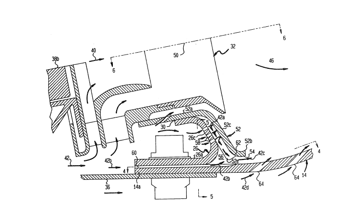
Illustrated in more particularity in Figures 2 and 3 is the inner support
plate 26 and the
inner carburetor 32 of the dome assembly 24 with it being understood that the
description of the
invention applies equally also to the outer support plate 268 and the outer
carburetor 328. Each
of the support openings 30 has a longitudinal centerline axis 50 about which
the carburetor 32
is disposed coaxially in !he support opening 30. A plurality of annular heat
shields or
splashplates 52 each has a proximal end 52a fixedly and sealingiy joined
coaxially to a
respective one of the support openings 30 by brazing for example; a distal end
52b spaced
radially outwardly away from the inner surface of the liner 14 to define a
circumferentialiy
extending outlet gap 54; and an intermediate flared portion 52c spaced axially
downstream from
the support plate intermediate portion 26c and radially ourivardly away from
the liner 14 to define
a circumferentially extending plenum 56 which is in flow communication with
the outlet gap 54.
The support plate intermediate portion 26c is preferably flat and includes a
plurality of
circumferentially and radially spaced impingement holes 58 disposed between
the support
openings 30 and the support plate proximal end 26a for channeling a first
portion of the
compressed air 42 as impingement air Jets 42a into the plenum 56 to impinge
against the
splashplate intermediate portion 52c for cooling thereof. A plurality of
circumterentially spaced,
axially extending air slots 60 are disposed between the support plate proximal
end 26a and the
liner upstream end 14a for channeling a second portion 42b of the compressed
air 42
therethrough and Into the pienum 56 for mixing with spent Impingement air 42a
which has firstly
Impinged against the spiashplate Intermediate portion 52c to form a cooling
air film 42c
extending from the outlet gap 54 along the inner surface of the liner 14 for
film cooling the liner
Patent 13DV-10547
2~~~~~~
-s-
14. The outer and inner liners 12, 14 have inner surfaces which face and
confine the combustion
gases 46 and the coding air film 42c flows along the inner surfaces thereof to
provide a
protective cooling air boundary layer.
In this embodiment of the present invention, a conventional, relatively
complex additional
cooling air nugget is not used for providing the cooling air film 42c, but
instead, the impingement
holes 58, air slots 60, and outlet gap 54 are predeterminedly sized and
configured for providing
the cooling air film 42c from the outlet gap 54, as well as for providing
impingement cooling of
the sptashplate 52 and increasing the transient temperature response of the
support plate
proximal end 26a at the liner upstream end 14a. More specifically, the
impingement hoses 58
ara located in the flat support plate intermediate portion 26c and not in the
curved apex portion
thereof bridging the intermediate portion 26c and the proximal end 26a for
reducing stress
concentrations. The compressed air 42 is first channeled as the impingement
air 42a for cooling
the splashplate 52 and then flows into the plenum 56. The air second portion
42b is channeled
through the air slots 60 for rapidly heating the flange joints formed by the
support plate proximal
end 26a, the liner upstream end 14a, and the cowl 36 during an engine
acceleration to Increase
the transient temperature response or growth of the flange joint for reducing
thermal stresses.
Similarly, on an engine decel, the air second portion 42b more quickly cools
the flange
joint for again reducing thermal stresses therein. The air second portion 42b
is similarly then
channeled into the plenum 56 wherein it is mixed with the spent impingement
air 42a and
discharged through the outlet gap 54 as the cooling air film 42c. In this way,
the compressed
air 42 is more efficiently utilized for not only providing the cooling air
film 42c but also
impingement cooling the splashplate 52 and increasing the transient response
of the flange joint.
Although the cooling air film 42c is hotter than it would be if provided by
conventional cooling
air nuggets provided directly with a portion of previously unused compressed
air 42, it
nevertheless is effective for providing film cooling of the liner 14.
In the exemplary embodiment illustrated in Figures 2 and 3. the liner upstream
end 14a
is substantially flat and the splashplate intermediate portion 52c at the
distal end 52b is generally
convex toward the pienum 56, or configured, to define a converging channel 62
for accelerating
the spent impingement air 42a and the air second portion 42b mixed therewith
from the pienum
56 and out the outlet gap 54 for creating a more effective cooling air film
42c. As illustrated in
more particularity in Figure 4, the air slots 60 are preferably configured for
diffusing the air
second portion 42b for providing a circumterentially uniform flow of the
cooling air film 42c from
the outlet gap 54. For example each of the air slots 60 includes a straight
upstream end 60a
having a constant width W,, and a diverging downstream outlet portion 60b
having a linearly
Increasing width from the first W~ to a maximum width of WZ at Its outlet. In
this way, the air
second portion 42b spreads circumferentially more quickly upon discharge from
the air slots 60
Por Improving the circumferential uniformity of the cooling air film 42c. Each
side of the air slot
Patent 13DV-10547
outlet portion 60b has a half angle H, indicating its degree of divergence,
which is less than
about 15°, and preferably 10°, for providing diffusion of the
air second portion 42b through the
slots 60 without flow separation, Also in the embodiment illustrated In Figure
4, each of the air
slots 60 is preferably aligned parallel to the longitudinal centerline axis t6
of the combustor 10.
The air slots 60 may have various configurations between the support plate
proximal end
26a and the liner upstream end 14a, and for example, as illustrated in Figures
3-5, the air slots
60 are preferably disposed, or recessed, in the inner surface of the liner 14.
They may be
suitably machined or cast into the liner 14 to a suitable depth d of about
0.5mm for example,
and be suitably spaced apart at a distance S, as shown in Figure 5, for
providing effective
thermal transient response of the flange joint as well as circumfereniiai
uniformity of the cooling
air film 42c. The height of the outlet gap 54 in this exemplary embodiment is
about l.8mm for
providing an effective pooling air film 42c.
Referring to Figures 2, 3, and 6, each of the splashplates 52 preferably
includes radially
extending, ciroumferentially spaced, opposite side edges 52e disposed in
abutment with the
95 support plate Intermediate portion 26c for seating leakage therethrough of
the spent impingement
air 42a and for confining the spent impingement air 42a to flow radialiy
through the pienum 56
and out the outlet gap 54. As shown more particularly in Figure 2, each of the
splashplates 52
(s annular about the centerline axis 50 with the proximal end 52a being
tubular, and the
intermediate portion 52c being generally rectangular. Each of the splashplates
52 has two distal
ends 52b, one at the bottom and one at the top spaced radially away from the
liner 14 and the
centerbody 28 for example, to define respective outlet gaps 54. The two
radially extending side
edges 52e of each splashplate 52 are disposed adjacent to respective side
edges 52e of
circumferentially adjacent splashplates 52.
In a conventional splashplate, radially extending gaps are provided between
the
splashplates from which air can leak. However, in accordance with one object
of the present
invention, the splashplate side edges 52e may be formed, by bending for
example, to not only
space the splashplate intermediate portion 52c axially away from the support
plate intermediate
portion 26c but also to provide an effective side seal at the junction of the
side edges 52e and
the support plate intermediate portion 26c. In this way, the spent impingement
air 42a
discharged from the impingement holes 58 into the plenum 56 is confined to
slow in a radial
direction toward and out of the outlet gaps 54 for more efficiently utilizing
the spent impingement
air 42a in providing an effective cooling air film 42p from the outlet gaps
54.
As illustrated in Figures 2-4, the inner liner 14, as well as the outer liner
12 and the
centerbody 28, may include in an exemplary embodiment a plurality of axially
spaced rows of
rearwardly inclined multiholes 64 disposed in the liner 14 downstream of the
outlet gap 54 for
channeling into the combustor 10 a third portion 42d of the compressed air 42
for both
convectively and film cooling the liner 14. In the exemplary embodiment
illustrated, the
Patent 13GV-1054%
.$.
multiholes 64 along are ineffective for providing a suitable cooling air film
along the inner surtace
of the liner 14 for protection against the combustion gases 46. However, as
described above.
the impingement holes 58, the air slots 60, and the outlet gap 54 may be
preferably sized for
providing an effective cooling air film 42c for starting film cooling from the
first row of multiholes
64. The starting cooling air film 42c then Jofns with the cooling air films
42d from the multlholes
64 for providing a continuous cooling air film from the outlet gap 54 and
downstream over the
entire axial length of the combustor 10.
Accordingly, the combustor dame assembly 24 of the present invention may be
used
in a new method of starting film cooling from the rows of the muitiholes 64
which includes
channeling the air first portion 42a through the impingement holes 58 to
impinge against the
splashplate Intermediate portion 52c to form spent impingement air. The method
further includes
channeling the air second portion 42b through the air slots 60 and into the
plenum 56 far mixing
with the spent Impingement air 42a therein. The method further includes
discharging the mixed
spent impingement air 42a and the air second portion 42b discharged from the
air slots 60 from
the plenurn 56 and through the outlet gap 54 as the cooling air film 42c for
starting film cooling
from the rows of the multiholes 64.
In a preferred embodiment of the invention, the velocity of the cooling air
film 42c
discharged from the outlet gap 54 in the axial downstream direction is
preferably about 2 to 3
times that of the velocity of the combustion gases 46 in the combustor 10,
which relatively high
velocity of the cooling air film 42c may be more efficiently obtained by
utilizing both the cooling
air first and second portions 42a and 42b combined in the plenum 56 and
accelerated through
the converging channel 62 to the outlet gap 54. Accordingly, the energy
available in the
compressed air 42 may be used for both impingement cooling the splashplate 52
and improving
transient thermal response of the flange joint at the air slots 60, with
suitable energy remaining
therein for providing an effective cooling air film 42c. Since pressure drops
occur across both
the impingement holes 58 and the air slots 60 which necessarily reduce the
velocity of the
cooling air 42 being channeling therethrough, both the converging channel 62
and the seals
provided by the splashplate side edges 52e are effective for improving the
efficiency of
channeling the compressed air 42 to the outlet gaps 54 for providing an
effective cooling air film
42c.
Furthermore, since a plurality of circumferentially spaced air slots 60 feed
the
circumferentially extending plenum 56 and outlet gap 54, the air second
portion 42c must be
suitably circumierentially spread upon discharge from the air slot 60 as above
described for
providing a clrcurnferentlally uniform cooling air film 42c for effectively
protecting the liner 14 as
well as effectively starting film cooling from the multiholes 64 uniformly
circumferentially around
the Liner 14.
Patent 13DV-10547
_g_
Although diverging air slots 60 disposed parallel to the combustor centerline
axis 16 are
illustrated in the preferred embodiment, including Figure 4, alternate
configurations of the air
slots 60 may also be used as shown in Figures 7-10. For example, illustrated
in Figure 7 is an
embodiment wherein the air slots, designated 60B simply have straight sides
aligned parallel to
the combustor longitudinal axis 16 and suitably closely spaced to each other
for collectively
providing a circumferentially uniform cooling air film 42c when mixed with the
spent impingement
air 42a. In Figure 8, each of the straight air slots, designated 60C, may b2
aligned at an acute
angle A relative to the longitudinal centerline axis 76 of the combustor 10.
In Figure 9, the air
slots may be in the form of two relatively narrow slots 60D, or double slots,
closely
circumferentially spaced relative to each other at a distance S, with the
circumferential spacing
S between adjacent ones of the double slots 60D being generally equal to that
of the diverging
air slots 60 illustrated in Figure 5. And, in Figure 10, the air slots
designated 60E may combine
the acute angle A orientation of the centerline thereof as shown in Figure 8
with the diverging
outlet portion 60b as shown in Figure 4. Other configurations and combinations
of
configurations of the alr slots 60 may also be used for both providing
effective transient thermal
response of the flange joint defined. at the air slot 60 as well as providing
the air second portion
42b into the plenum 56 for providing an effective and circumferentially
uniform cooling air film
42c from the outlet gap 54. Slot size, shape, and configuration may be
suitably adjusted to
optimize any particular design.
As disclosed above, the combustor dome assembly 24 may be configured for
providing
a respective outlet gap 54 at the upstrearm end of the inner surface of the
radial inner liner 14,
as well as at the upstream end of the inner surface of the outer liner 12, and
at both upstream
ends of the outer surface of the centerbody 28 for providing film cooling
thereof. The resulting
combustor dome assembly 24 has reduced weight, complexity, and man:dacturing
cost in
comparison to using conventional film cooling air starting means including
nuggets, and
eliminates small-hole stress concentrations in high stress areas of the dome
such as at the apex
joining the support plate proximal end 26a to the support plate intermediate
portion 26c. And,
most significantly, more efficient use is made of the compressed air 42
channeled firstly arxi
separately through both the impingement holes 58 and the air slots 60 and then
collectively
through the outlet gaps 54 for providing film cooling of the combustor liners
facing and confining
the combustion gases 46 therein.
'Nhile there have been described herein what are considered to be preferred
embodiments of the present invention, other modifications of the invention
shall be apparent to
those skilled in the ari from the teachings herein, and it is, therefore,
desired to be secured in
the appended claims all such modifications as fail within the true spirit and
scope of the
invention.