Note: Descriptions are shown in the official language in which they were submitted.
WO 91/09203 PCI`/US90/07510
.
' 2 ~ 7 0 6 3 ~
DOWNHOLE DRILL BIT AND BIT COUPLING
Summary Of The Invention
The present invention relates generally to downhole
drills having notable utility in drilling enlarged holes
for overburden casings and relates more particularly to a
new and improved drill bit and drill bit coupling for such
downhole drills.
A principal object of the present invention is to
provide a new and improved drill bit and drlll bit coupling
which are useful in drilling enlarged holes for overburden
casings and which permit installation and withdrawal of the
bit through the internal bore of the overburden casing.
Another object of the present invention is to provide
a new and improved downhole drill bit having in a retracted
or working position thereof a relatively large working
diameter and in an extended or non-working position thereof
a relatively small diameter enve~ope facilitating
installation of the bit into and withdrawal of the bit from
the drilled hole.
A further object of the present invention is to
provide a new and improved impact drill bit which fulfills
one or more of the foregoing objects of the present
invention and which has an impact head with an integral
impact bit sector for impact drilling an enlarged hole as
the impact bit is rotated during drilling. In accordance
with an additional object of the present invention, the
body of the impact drill bit forming the body of both the
impact head and an impact head drive shank, is a one-piece,
integrally formed part and the impact head comprises a
leading, pilot impact bit for drilling a relatively small
diameter guide hole and a trailing, impact bit sector for
drilling a substantially larger diameter hole as the bit is
rotated during drilling.
A further object of the present invention is to
provide a new and improved drill bit coupling for a
WO91/09203 PCT/US90/07510
` ~070~3~
downhole drill for coupling a drill bit in a new and
improved manner which provides for positioning the bit
either in a relatively large diameter, working position for
drilling a hole in a conventional manner or in a
non-working position having a relatively small diameter
envelope which facilitates installing the bit into and
withdrawing the bit from the drilled hole. In ac~ordance
with an additional object of the present invention, khe bit
in its working position is operable for drilling a
relatively large diameter hole for an overburden casing and
in its non-working position can be installed and withdrawn
through the smaller diameter bor~ of the overburden casing.
A further object of the present invention is to
provide a new and improved downhole drill bit which
fulfills one or more of the foregoing objects of the
present invention, which is useful in downhole impact
drilling and which has an economical design that can be
manufactured at relatively low cost.
Other objects will be in part obvious and in part
pointed out more in detail hereinafter.
A better understanding of the invention will be
obtained from the following detailed description and
accompanying drawings of preferred embodiments of the
present invention.
Brief Description Of The Drawings
In the drawings:
Fig. ~ is a longitudinal section view, partly in
section, of a downhole impact bit incorporating the present
invention;
Figs. 2 and 3 are transverse section views, in
section, of the bit of Fig. l taken substantially along
lines 2-2 and 3-3 of Fig. l;
Fig. 4 is an enlarged front end view of the bit of
Fig. l;
WO91/092~3 PCT/US90/07~10
06
..... .. .
Fig. 5 is an enlarged rear end viaw of the bit of Fig.
l;
Fig. 6 is a partial longitudinal section view, partly
broken away and partly in sec:tion, of a downhole impact
drill installation employing the impact bit of Fig. 1 and
an impact bit coupling inco~orating the present invention;
Figs. 7 and 8 are longitudinal section views, partly
broken away and partly in section, of the installation of
Fig. 6 showing the downhole impact drill in first and
second stages of withdrawal from a drilled hole;
Fig. 9 is a partial longitudinal section view, partly
broken away and partly in section, of a downhole impact
drill employing modified embodiments, incorporating the
present invention, of the impact bit and impact bit
coupling of Figs. 6 - 8; and
Fig. 10 is a partial longitudinal view, partly broken
away, of the downhole impact drill of Fig. 9, taXen in the
direction of arrows 10-10 of Fig. 9 and showing a chuck and
bit retainer ring of the drill.
Description Of Preferred Embodiments
Referring now to the drawings in detail, wherein like
numerals are used to designate the same or like parts, and
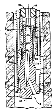
referring particularly to Figs. 6 - 8, a pneumatic,
downhole impact drill 8 is shown which employs a drill bit
10 and drill bit coupling 11 incorporating the present
invention. ~he drill bit 10 has a rear, elongated drive
shank 12 and a front, enlarged drill bit impact head 14.
The elongated body of the bit 10, comprising the body of
both the drive shank 12 and impact head 14, is preferably a
one piece, integrally formed part which is manufactured by
machining a suitable length of large diameter bar stock or
forging.
A downhole hammer 20 of the drill 8 is shown only in
part in Figs. 6 - 8. Except as specifically described
WO 91/09203 PCr/US90/07510
h~)70~3d~:
hereinafter, the downhole ha~mer 20 may be like that shown
and described in United states Patent 4,530,408, dated July
23, 1985 and entitled "Porting System for Pneumatic Impact
Hammèr". Referring to Figs. 6 - 8 and to U.S. Patent
4,530,408 (which is incorporated herein by reference), the
drive shank 12 of the bit lO is mounted in the front end of
the hammer 20 so that an impact piston 18 of the hammer 20
can be pneumatically reciprocated in a conventional manner
to impact a rear anvil end face 16 of the drive shank 12 at
a high frequency for downhole impact drilling.
The bit 10 is axially shiftable within the front end
of the downhole hammer 20 between an inner or retracted,
working position shown in Fig. 6 and an outer or extended,
non-working position shown in Figs. 7 and 8. In the
extended, non-working position of the bit 10, the drive
shank 12 is supported, by means of a bit retaining ring 22,
on a rear annular end face 23 of an externally threaded
chuck or sleeve 24 screwed into the front end of th~ hammer
casing 26. In the retracted, working position of the bit
lO, a rear annular shoulder 28 of the impact head 14 and a
front annular end face 30 of the chuck 24 are in
engagement. Thus, the chuck 24 and retaining ring ~2
together support and retain the drill bit 10 within the
hammer 20. As will be understood from the following
description, the bit coupling 11 is formed by the
cooperating parts of the bit 10, chuck 24 and retaining
ring 22.
The bit lO is removed from the hammer 20 by unscrewing
the chuck 24 from the hammer casing 26, removing the
subassembly comprising the bit 10, chuck 24 and retaining
ring 22, removing the two semi-circular halves of the split
retaining ring 22 from the drive shank 12 and then removing
the bit 10 from the chuck 24.
In the retracted, working position of the bit 10, the
impact bit 10 is coaxially mounted within the chuck 24 and
WO91/09203 PCT/US90/07~10
2~7063~
impact hammer 20. Enlarged, front and rear guide sections
32, 34 of the shank 12 assist in positioning the bit 10
coaxially within the chuck 24. The front guide section 32
is received within an enlarged, front coaxial bore 38 of
the chuc~ 24 to coaxially position the front end of the bit
lO. The rear guide section 34 cooperates with a bearing
sleeve 36 mounted within the hammer casing 26 to coaxially
position the rear end of the bit 10. Also, the chuck 24
and bit drive shank 12 have cooperating internal and
external splines 90, 92 (described more fully hereinafter)
which assist in coaxially positioning the bit 10 within the
hammer 20 with the bit 10 in its retracted, working
position.
-The drill bit head 14 comprises a leading, pilot
impact bit 40 and a trailing, impact bit sector 42 which is
largely located on one side of the bit axis 82 (i.e., on
one side of a diametral plane). In the shown embodiment,
the body of the impact bit sector 42 is integrally formed
with the body of the pilot bit 40. (Also, as previously
indicated, the entire body of the bit 10, comprising the
body of both the shank 12 and impact head 14, is pre~erably
provided by a one-piece integrally formed part.)
The pilot bit 40 produces a pilot or guide hole for
the drill 8. The trailing drill bit sector 42 produces an
enlarged hole as the impact drill 8, including the bit 10,
is rotated in a conventional manner during drilling. The
drill bit sector 42 has an outer diameter suhstantially
greater than that of the pilot bit 40. For example, when
the bit 10 is used with a standard size hammer 20 having an
outside diameter of 5-3/8 inches, the pilot bit 40 is
dimensioned to produce a pilot hole having a diameter of
approximately three and one-half (3-l/2) inches and the
drill bit sector 42 is dimensioned to enlarge the pilot
hole to a diameter of approximately seven and one-half
~7-1/2) inches.
WO91/Og203 PCT/VS90/07510
`'2Q7Q~ 6
Referring to Fig. 6, the bit lO is particularly useful
in drilling an enlarged hole for an overburden casing 50.
In a generally conventional manner, the overburden casing
50 is fed into the hole during drilling. For that purpose,
a drive shoe 52 is welded to the front end of the
overburden casing 50 and the drill chuck 24 is formed with
a plurality of peripheral, integral drive lugs 54 (of which
there are four in the disclosed embodiment) for engagement
with the rear end of the drive shoe 52. The drive lugs 54
are slidable within the overburden casing 50 into
engagement with the rear end of the drive shoe 52.
Specifically, a drive shoe sleeve 56 received in the
overburden casing 50, has a rear, tapered end shoulder 58
which is engageable by conforming, tapered, peripheral
shoulders 60 of the drive lugs 54. Accordingly, as seen in
Fig. 6, as the impact drill 8 is fed into the drilled hole,
the overburden casing 50 is fed into the hole immediately
behind the drill bit sector 42.
Suitable carbide impact buttons 62 (mounted within
bores in the body of the impact head 14) are provided on
the working faces of the pilot bit 40 and impact bit sector
42 as shown in Fig. 4. An annular arrangement of six
equiangularly spaced impact buttons 62 is provided on a
peripheral conical working face 64 of the pilot bit 40.
Two diametrically opposed impact buttons 62 are provided at
different radii on a central flat end face 65 of the pilot
bit 40. The drill bit sector 42, at its inner perimeter,
has a conical working face 68 which extends nearly
completely around the pilot bit 40 and, at its outer
perimeter, has a conical working face 70 which extends
approximately one hundred twenty degrees (120) around
the pilot bit 40. Four impact buttons 62 are provided at
two different radii on the inner conical working face 68,
located symmetrically relative to the radial centerline 84
of the bit sector 42 along an arc of approximately one
WO91/09203 PCT/US90/07510
7 207~3~
hundred eighty degrees (180). Three buttons 62 are
provided on the outer conical working face 70, with one
button 62 located on the cen~erline 84 and the remaining
two buttons 62 located symmetrically relative to the
centerline 84 and approximately eighty degrees (80)
apart.
The drive shank 12 and a rear cylindrical section 72
of the enlarged drill bit head 14 are machined coaxial with
the hit 10. The cylindrical surface of the rear
cylindrical section 72 extends axially forwardly along that
part of the drill bit head 14 which is aligned with the
drill bit sector 42. The central flat end face 65 and
peripheral conical working face 64 of the pilot bit 40 are
machined coaxially with the bit. The conical wor~ing faces
68 and 70 of the drill bit sector 42 and the sur~ace
between the working faces 68, 70 of the drill bit sector 42
and pilot bit 40 are machined coaxial with ~he bit. The
outer surface 73 of the drill bit sector 42, which extends
approximately eighty degrees (80) around the pilot bit
40, is machined coaxial with the bit 10. The remaining
surfaces of the impact head body are machined about an
offset axis 80 which is parallel to the bit axis 82 and
offset from the bit axis along the radial centerline 84 of
the bit sector 42. The impact head 14 is machined in
steps. First, the bit lO is machined about the bit axis 82
to produce the describe~ coaxial surfaces. Thereafter, the
impact head 14 is machined about the o~fset axis 80 to
produce the non-coaxial surfaces of the impact head body.
The chuck 24 and bit drive shank 12 have respective
internal and external, cooperating splines 90, 92. In the
shown embodiment, the chuck 24 and drive shank 12 each have
eight eguiangularly spaced, parallelj axial splines.
Referring to Figs. 1-3, the eight external splines 92 of
the drive shank 12 are composed of primary and secondary,
preferably contiguous, spline sections 96, 98 having
WO91/09203 PCT/US90/07510
` 2070634 8
different siæe spline segments. The spline segments 92a of
the front or primary spline section 96 have larger outer
and root diameters and a greater circumferential thickness
than the spline segments 92b of the rear or secondary
spline section 98.
The primary spline segments 92a are substantially
longer than the secondary spline segments 92k as best shown
in Fig. l. The primary spline segments 92a are received
between the internal splines 90 of the chuck 24 when the
bit lO is in its retracted, working position shown in Fig.
6. In that position of the bit lO, the spline segments 92a
cooperate with the internal splines 90 of the chuck 24 to
provide a drive coupling for rotating the bit lO during
drilling in a conventional manner. The primary spline
segments 92a and internal splines 90 are mating splines
having the same thickness and are sized to provide a rigid
drive coupling and to assist in positioning the bit lO
coaxially within the hammer 20. The primary spline
segments 92a have a reduced height which is less than the
conventional spline height of the internal splines 90.
The rear guide section 34 of the drive shank 12 is
formed with splines aligned with and having substantially
the same size as the primary splines 92a to permit
insertion and withdrawal of the rear guide section 34
through the chuck 24. A reduced, elongated rear end
section 99 of the drive shank 12 is provided between the
rear spline segments 92b and rear guide section 34. That
rear end section 99 has a diameter equal to the root
diameter of the rear spline segments 92b. The enlarged
front end bore 38 of the chuck 24 has a diameter somewhat
greater than the outer diameter of the primary splines 92a.
With the bit in its extended, non-working position
sh~wn in Figs. 7 and 8, only the rear, secondary spline
segments 92b are received between the internal splines 90
of the chuck 24. In that extended position of the bit lO,
,
WO91/09203 PCT/US90/07510
`~ 2~7~3'~
the secondary spline segments 92b cooperate with the
internal splines 90 of the chuck 24 to provide a loose
drive coupling which prevents rotation of the bit 10 within
the chuck 24 and thereby maintain the angular orientation
o~ the bit 10 within the chuck 24. Also, the reduced rear
end section 99, reduced raar spline section 98 and reduced
height of the primary spline segments 92a o~ the drive
shank 12 and the enlarged front end bore 38 o~ the chuck 24
are sized to permit limited lateral play or movement of the
bit 10 within the chuck 24. As shown in Figs. 7 and 8,
with the bit 10 in its extended, non-workiny position, the
front guide section 32 of the drive shank 12 is forward of
the chuck 24 to free the front end of the bit 10 for
lateral movement. Also, with the bit 10 in that extended
position, because there is a slight clearance and only a
short axial overlap between the rear guide section 34 and
the bearing sleeve 36, the bit lO is free to swing or pivot
laterally within the chuck 24 about its rear end.
In the disclosed embodiment, the bit 10 is free to
swing or pivot approximately three degrees (3) from its
coaxial or working position shown in Fig. 6. That
available play or movement permits the drill bit sector 42
to swing inwardly to reduce the diameter of the envelope of
the enlarged drill head 14 and thereby enable the head 14
to be withdrawn through the overburden casing drive shoe
52. With the bit 10 free to swing within the chuck 24 as
described, the bit 10 can be installed and withdrawn
through the overburden casing 50 and drive shoe 52 and
therefore throùgh an opening substantially less that the
diameter of the drilled hole.
Installation and withdrawal of the bit 10 through the
overburden casing 50 and drive shoe 52 is accommodated
automatically upon installation of the drill 8 into and
withdrawal of the drill 8 from the casing 50. Upon initial
withdrawal of the drill 8, the bit 10 shifts outwardly to
WO91/09203 PCT/US90/07510
~0~3~ lo
its extended, non-working position due to gravity. Further
withdrawal of the drill 8 withdraws the bit lO through the
drive shoe 52 and overburden casing 50. In the extended
position of the bit lO, the drill bit head 14 is free to
swing within the chuck 24 sufficiently to clear the drive
shoe 52. The tapered rear face lO0 of the drill bit sector
42 and the opposing peripheral tapered surface 102 of the
drill head 14 assist in guiding the drill head 14 upwardly
through the reduced diameter opening of the drive shoe 52.
The lateral freedom of movement of the bit 10 also
accommodates installation of the drill bit 10 through the
overburden casing 50 and drive shoe 52. When lowering thé
drill, after the bit lO engages the bottom of the hole, the
bit 10 is retracted to its working position from its
extended, non-working position. As the bit 10 is
retracted, the bit is automatically swung into coaxial
position by the interaction of the external splines 92 of
the drive shank 12 with the internal splines 90 of the
chuck 24. Specifically, the primary external spline
segments 9~a cooperate with the internal splines 90 of the
chuck 24 and with the tapered shoulder at the front end of
the internal splines 90 to swing the bit 10 into coaxial
position as the bit is retracted into the chuck 24.
In place of the secondary spline segments 92k, other
means (not shown) could be used to assist in orienting the
bit 10 for retraction to its working position. For
example, the front ends of the internal splines 90 of the
chuck 24 and the rear ends of the primary spline segments
92a could be specially contoured for engagement for both
angularly orienting the bit and assisting in coaxially
orienting the bit for retraction to its working position.
In the extended, non-working position of the bit lO,
the bit lO is supported on the bit retainer ring 22 by a
front, intermittent, but generally annular shoulder 106 of
the rear guide section 34. Referring to Figs. 7 and 8, the
WO91/09203 PCT/US90/07510
11 2~63~
bit support shoulder 106 is machined for supparting the bit
10 at an angle having the desixed inclination to the hammer
axis. In the described embodiment, the annular support
shoulder 106 is machined about an axis inclined three
degrees (3) to the axis of the bit 10. Therefore~ when
the support shoulder 106 engages the mating shoulder 108 of
the retainer ring 22, the bit 10 is automatically swung
three degrees (3) from the hammer axis. In that angled
position of the bit 10, the offset machined surfaces of the
drill bit sector 42 are approximately coaxial with the
chuck 24 (i.e., the offset machining axis 80 crosses the
chuck axis approximately at the transverse plane of the bit
sector 42) and such that the diameter of the drill bit head
envelope is substantially less than when the bit 10 is in
its retracted, working position. To swing the bit 10 in
the appropriate direction, the axis of the annular support
shoulder 106 is inclined away from the bit axis in the
direction of the radial centerline 84 of the drill bik
sector 42. In other words, the support shoulder 106 is
machined at an angle to swing the drill bit sector 42
radially inwardly along the radial centerline 84 when the
support shoulder 106 engages the retainer ring 22.
Instead of providing an angled support shoulder 106 on
the guide section 34 as described, (a) the rear end face 23
of the chuck or (b) the mating rear annular support
shoulder 108 of the retainer ring 111 could be machined at
that same angle as shown by the angled surface 112 in Fig.
9. In each of those alternatives, the bit 10 must be
properly oriented relative to the chuck 24 for swinging the
drill bit sector 42 inwardly as described. In addition, in
the latter alternative shown in Figs. 9 and 10, the
retainer ring 111 must be properly oriented relative to the
chuck. For that reason, the retainer ring 111 is keyed to
the chuck 24 by one or more integral keys 109 rereived
within corresponding slots 110 ln the rear end face 23 of
the chuck 24 as shown in Fig. 10.
WO91/09203 PCT/US90/07~10
~ ~ 7 ~ 12
As will be apparent to persons skilled in the art,
various modifications, adaptations and variations of the
foregoing specific disclosure can be made with~ut departing
from the teachings of the present invention.