Language selection

Search

Patent 2070801 Summary

Third-party information liability

Some of the information on this Web page has been provided by external sources. The Government of Canada is not responsible for the accuracy, reliability or currency of the information supplied by external sources. Users wishing to rely upon this information should consult directly with the source of the information. Content provided by external sources is not subject to official languages, privacy and accessibility requirements.

Claims and Abstract availability

Any discrepancies in the text and image of the Claims and Abstract are due to differing posting times. Text of the Claims and Abstract are posted:

  • At the time the application is open to public inspection;
  • At the time of issue of the patent (grant).
(12) Patent: (11) CA 2070801
(54) English Title: TILT TRAY SORTER ACCESSORY
(54) French Title: ACCESSOIRE DE TRIEUSE A CORBEILLES A BASCULE
Status: Deemed expired
Bibliographic Data
(51) International Patent Classification (IPC):
  • B07C 3/02 (2006.01)
  • B07C 3/08 (2006.01)
  • B65G 47/61 (2006.01)
(72) Inventors :
  • RICHARDSON, DESMOND HAIG (Australia)
(73) Owners :
  • AUSTRALIAN POSTAL CORPORATION (Australia)
(71) Applicants :
(74) Agent: CASSAN MACLEAN
(74) Associate agent:
(45) Issued: 2001-05-01
(86) PCT Filing Date: 1991-12-12
(87) Open to Public Inspection: 1992-07-09
Examination requested: 1996-11-15
Availability of licence: N/A
(25) Language of filing: English

Patent Cooperation Treaty (PCT): Yes
(86) PCT Filing Number: PCT/AU1991/000581
(87) International Publication Number: WO1992/011098
(85) National Entry: 1992-06-09

(30) Application Priority Data:
Application No. Country/Territory Date
PK3927 Australia 1990-12-17

Abstracts

English Abstract


An accessory (10) for a tilt tray sorter comprises a frame (11) and
is adapted to be suspended by a fixture (12) from a transport mechanism
of the type usually associated with conventional parcel sorting
equipment. The frame (11) carries two or more tilting trays (14) which
are attached by pivots (15) to the frame (11). Each of the tilting trays
(14) has associated with it, a tilting mechanism (16) which comprises a
pair of parallel rods (17) suspended below each tray. In addition, a
bracket (18) is provided above each tray (14). The bracket carries a cam
(19). The cam (19) pivots about an upper axis (20). The side of the cam
which faces the tray (14) carries a stub (21). The stub (21) is received
between the parallel rods (17). Thus, as the cam (19) pivots and returns
to its rest position, the tray (14) is displaced from a level position to
a tipped position and back again.


French Abstract

Accessoire (10) pour dispositif de triage à plateaux culbutables. Il comporte un cadre (11) et peut être suspendu à partir d'un élément (12) faisant partie d'un mécanisme transporteur du type qui est normalement associé aux installations traditionnelles de triage de paquets. Le cadre (11) porte au moins deux plateaux culbutables (14) montés sur le cadre (11) par l'intermédiaire de pivots (15). Un mécanisme de pivotement (16) est associé à chacun de plateaux (14) et comporte une paire de tiges parallèles (17) sous-jacentes. Par ailleurs, une console (18) est montée au-dessus de chaque plateau (14) et porte une came (19) pouvant pivoter autour d'un axe supérieur (20). La came porte un tenon (21) sur le côté qui se trouve en regard du plateau (14), ledit tenon (21) étant reçu entre les tiges parallèles (17). Ainsi, à mesure que la came (19) pivote et revient à sa position de repos, le plateau (14) passe de sa position horizontale à une position inclinée puis retourne à la position de départ.

Claims

Note: Claims are shown in the official language in which they were submitted.


-4-

CLAIMS

1. A sorting system comprising a loading station and at least one receiving
station
spaced from the loading station, a transport mechanism arranged between said
loading station
and said at least one receiving station a pendant frame suspended from said
transport
mechanism and moving between said loading station and said at least one
receiving station,
two or more tilting trays mounted on said frame at different levels, one above
the other, an
independent tipping mechanism associated with each tray for tipping the tray
and two or more
actuating mechanisms at said at least one receiving station arranged at
different levels
corresponding to the levels at which said two or more trays are mounted on
said frame, each
actuating mechanism independently, selectively actuating the tipping mechanism
of the tray
mounted on the frame at the corresponding level.
2. An accessory according to claim 1, wherein the frame is provided with three
trays each arranged to pivot about a substantially horizontal axis with
respect to the frame.
3. An accessory according to claim 1 or, wherein each independent tipping
mechanism comprises a cam member pivotally mounted on the frame and engaging a
cam
engaging means on the tray, whereby when the cam member is pivoted, the tray
is tipped.
4. An accessory according to claim 3, wherein the cam member comprises a
pivoting plate provided with an arm member which engages between two rods
mounted on an
underside of the tray.
5. An accessory according to claim 4, wherein the actuating mechanism
comprises
a cam actuator and the pivoting plate is arranged for riding over the cam
actuator and pivoting
the cam member, whereby tipping the tray.
6. An accessory according to claim 1, wherein each tipping mechanism is
provided
with means for keeping the tray in a tipped position until released.


-5-

7. An accessory accord ng to claim 6, wherein the means for keeping the tray
in a
tipped position comprises a latch to hold the cam member in a pivoted position
so that the tray
remains tipped until the latch is released.
8. A sorting system comprising:
a loading station;
an outlet station;
a frame having upper and lower portions;
transport means for supporting the frame pendantly from the upper portion of
the frame
and transporting the frame from the loading station to the outlet station;
at least two trays mounted on the lower portion of the frame at respective
levels tippably
about respective axes that are parallel to the transporting;
tipp ng means respectively for each of the trays, each of the tipping means
having first
means for holding its associated tray level and second mans for tipping the
associated tray; and
actuating means respectively for the trays at the outlet station at the
respective levels of
the trays, each of the actuating means operating the second means for tipping
its associated
tray when the transport means has transported the frame to the outlet station.

Description

Note: Descriptions are shown in the official language in which they were submitted.


- 1 - 20'0803.
TILT TRAY SORTER ACCESSORY
MELD OF THE INVENTION
The invention pertains to parcel sorting and more particularly to a
an accessory for a tilt tray sorter arrangement which would provide
multiple level sorting.
BACKGROUND OF ZHE INVENTION
Commercially available sorters consist of a transport system,
usually of a chain conveyor construction, which carries trays on the top
of an endless chain. These trays are loaded with items to be sorted,
carried to a selected outlet position and tipped, whereby the item
carried is dropped into a receptacle. The trays are reset before
re-entering the loading area. However, existing transport systems are
limited to a single level of trays. ,
One conventional tilt tray sorter generally comprises a moving
chain which can carry a tilting element which includes a tray and a
tilting mechanism. Such a parcel handling device, for example the 3D
Tilt Tray Sorter is available from Beumer Pty Limited, 293A Seaview Road,
Henley Beach, South Australia, 5022.
SUMMARY OF THE INVENTION
It is an object of the invention to substantially ameliorate some
of the disadvantages of prior art tilt tray sorters.
Accordingly, the invention provides an accessory for a tilt tray
sorter including a transport mechanism, the accessory comprising a frame
rihich carries two or more tilting trays arranged one above the other, an
independent tipping mechanism associated with each tray for tipping the
tray and mounting means on the frame for mounting the accessory on the
transport mechanism.
In a preferred embodiment, the frame is provided with three trays
each arranged to pivot about a substantially horizontal axis with respect
to the frame. Preferably, each independent tipping mechanism comprises a
cam member pivotally mounted on the frame and engaging a cam engaging
means on the tray, whereby when the cam member is pivoted, the tray is
tipped. -~
The cam member preferably comprises a pivoting plate provided with
an arm member which engages between two rods mounted on an underside of
the tray. The pivoting plate is preferably arranged for riding over a
cam actuator provided on the sorter for pivoting the cam and therefore
tipping the tray. The cam actuator is selectively movable into a
position where the pivoting plate rides over the cam actuator.


- ~ - 2070$01
Preferably also, each tipping mechanism is provided with a latch to
hold the cam member in a pivoted position so that the tray remains tipped
until the latch is released.
_BRIEF DESCRIPTIO~J OF THE DRAWINGS
One embodiment of an accessory for a tilt tray sorter according to
the invention will now be more fully described, by way of example, with
reference to the drawings, of which:
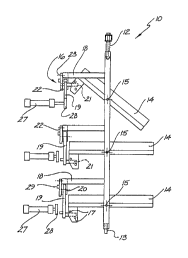
Figure 1 is a front elevation of an accessory according to one
embodiment of the present invention; and
Figure 2 is a side elevation of the accessory depicted in Figure 1.
~TAI~FD DESCRIPTION OF THE DRAWING
As shown in Fig. 1, the accessory 10 according to one embodiment of
the present invention comprises a frame 11 and an upper fixture 12. The
accessory 10 is adapted to be suspended by the fixture 12 from a
transport mechanism of the type usually associated with conventional
parcel sorting equipment. If required, the frame 11 may include
additional means 13, located at the base of the frame 11 for fixing the
frame to guide rails or a second transport track to ensure that the frame
11 remains erect. The frame 11 carries two or more tilting trays 14
which are attached by pivots 15 to the frame 11. Each of the tilting
trays 14 has associated with~it, a tilting mechanism 16. The method used
to tip the trays, that is the tilting mechanism, may be any one of a
number of conventional tipping mechanisms presently in use. One,
particularly advantegous mechanism is described herein by way of example.
In this particular embodiment, the tilting mechanism comprises a
pair of parallel rods 17 which are suspended below each tray. In
addition, a bracket 18 is provided above each tray 14. The bracket
carries a cam 19. The cam 19 pivots about an upper axis 20. The side of
the cam which faces the tray 14 carries a stub 21. The stub 21 1s
received between the parallel rods 17. Thus, as the cam 19 pivots and
returns to its rest position, the tray 14 is displaced from a level
position to a tipped position and back again. The bracket 18 also
carries a~latch 22. The latch 22 pivots about an upper axis 23. The cam
19 carries, at a lower, end and on a side facing away from the tray 14,
first and second latching pins 24, 25. When the cam 19 is rotated
towards the latch, one or both pins 24, 25 engage a ramp surface 26 on a
lower end of the latch and cause the latch to pivot out of the way. The
first Latch pin 24 eventually contacts a flat surface of the latch thus


_ ; _ 2o~oso~
causing the latch to return to its original position and thereby causing
the latch to engage and retain the second latch pin 25.
As depicted in Fig. Z, the tilting trays 14 are normally in a Level
position. At a particular tipping station, they pass by a pneumatic
cylinder 27 which carries a round cam actuator 28 at the end of its
piston. If the piston is retracted, no contact is made between the cam
19 and the actuator 28. If the piston is extended, the cam 19 will ride
over the actuator 28 thus causing the tipping mechanism to displace the
tilting tray 14 from its normally level position.
At a separate location, the tray may be restored to the level
position, solely under the influence of gravity, by releasing the latch
mechanism from the second pin 25. This may be achieved in any
conventional manner. In a preferred embodiment, the side of the latch 22
which faces away from the tray 14 carries a short ramp 29 which is used
- 15 for this purpose.
While the present invention has been described with reference to
particular details of construction, these should be seen as having been
provided by way of example and not as limitations to the scope of the
invention.

Representative Drawing
A single figure which represents the drawing illustrating the invention.
Administrative Status

For a clearer understanding of the status of the application/patent presented on this page, the site Disclaimer , as well as the definitions for Patent , Administrative Status , Maintenance Fee  and Payment History  should be consulted.

Administrative Status

Title Date
Forecasted Issue Date 2001-05-01
(86) PCT Filing Date 1991-12-12
(85) National Entry 1992-06-09
(87) PCT Publication Date 1992-07-09
Examination Requested 1996-11-15
(45) Issued 2001-05-01
Deemed Expired 2003-12-12

Abandonment History

There is no abandonment history.

Payment History

Fee Type Anniversary Year Due Date Amount Paid Paid Date
Application Fee $0.00 1992-06-09
Registration of a document - section 124 $0.00 1992-12-18
Maintenance Fee - Application - New Act 2 1993-12-13 $100.00 1993-11-29
Maintenance Fee - Application - New Act 3 1994-12-12 $100.00 1994-12-01
Maintenance Fee - Application - New Act 4 1995-12-12 $100.00 1995-12-01
Request for Examination $400.00 1996-11-15
Maintenance Fee - Application - New Act 5 1996-12-12 $150.00 1996-11-20
Maintenance Fee - Application - New Act 6 1997-12-12 $150.00 1997-09-08
Maintenance Fee - Application - New Act 7 1998-12-14 $150.00 1998-11-16
Maintenance Fee - Application - New Act 8 1999-12-13 $150.00 1999-12-03
Maintenance Fee - Application - New Act 9 2000-12-12 $150.00 2000-12-04
Expired 2019 - Filing an Amendment after allowance $200.00 2000-12-13
Final Fee $300.00 2001-02-01
Maintenance Fee - Patent - New Act 10 2001-12-12 $200.00 2001-11-19
Owners on Record

Note: Records showing the ownership history in alphabetical order.

Current Owners on Record
AUSTRALIAN POSTAL CORPORATION
Past Owners on Record
RICHARDSON, DESMOND HAIG
Past Owners that do not appear in the "Owners on Record" listing will appear in other documentation within the application.
Documents

To view selected files, please enter reCAPTCHA code :


To view images, click a link in the Document Description column. To download the documents, select one or more checkboxes in the first column and then click the "Download Selected in PDF format (Zip Archive)" or the "Download Selected as Single PDF" button.

List of published and non-published patent-specific documents on the CPD .

If you have any difficulty accessing content, you can call the Client Service Centre at 1-866-997-1936 or send them an e-mail at CIPO Client Service Centre.


Document
Description 
Date
(yyyy-mm-dd) 
Number of pages   Size of Image (KB) 
Cover Page 2001-04-17 1 52
Cover Page 1994-02-26 1 13
Claims 2001-02-01 2 70
Claims 2000-12-08 2 70
Representative Drawing 2001-04-12 1 6
Abstract 1994-02-26 1 18
Claims 1994-02-26 1 31
Drawings 1994-02-26 2 29
Description 1994-02-26 3 122
Representative Drawing 1999-08-25 1 12
Prosecution-Amendment 2000-12-13 6 221
Prosecution-Amendment 2000-12-08 5 177
Fees 2000-12-04 1 32
Correspondence 2001-02-13 1 18
Correspondence 2001-02-01 1 55
Prosecution-Amendment 2001-02-01 2 99
Assignment 1992-06-09 8 226
PCT 1992-06-09 13 452
Prosecution-Amendment 1996-11-15 2 81
Fees 1996-11-20 1 104
Fees 1995-12-01 1 88
Fees 1994-12-01 1 95
Fees 1993-11-29 1 95