Note: Descriptions are shown in the official language in which they were submitted.
2~7~.9~
HEADSET AND USE HEREOF
STATE OF THE ART
The invention relates to a telephone headset as set forth
in the preamble of claim 1.
Quite a number of different types of telephone headsets are
known, which are arranged to be carried on a person's outer
ear only, in that the headset comprises a sound reproducer
with a telephone or a loudspeaker, a support member which
is often designed so as to be at least partly adapted to
the shape of the outer ear and in such a manner that the
sound reproducer is positioned opposite the sound entrance
of the ear, and a microphone arm or bar with a microphone.
.
Such a telephone headset is known for instance from appli-
cant's Danish patent no. 157,289 and the corresponding US
patent no. 4,893,344. This telephone headset further com-
prises means, viz. an adjustable stabilizer for individual
; ad~ustment, and comprises an ad~ustable microphone arm for
individual positioning of the microphone. Thus, the tele-
phone headset comprises a number of parts which are rotat-
able or displaceable in relation to each other, whereby
individual adjustment is achieved and so that the telephone
headset may be carried on the right or the left ear as
desired. The large number of parts and their movability
increase the costs of production and assembly of a tele-
phone headset, and further, it has turned out that some
headset users find it difficult to quickly adapt the many
possibilities of adjustment when moving the telephone head-
set, e.g. from the left to the right ear.
From international application no. PCT/SE90/00121 ~WO
90/10361) is known a telephone headset in which a sound
reproducer and a sound receiver are attached to an inel-
13313, 03/06-1992
:':, : ::
:, : ,:: : ::: ~ : ' :.
. : :," ': ' , : ~ :
2 2~7~ 6
astlcally pliable support member. The support member com-
prises a nose curve or arch adapted to rest on the ridge of
the user's noser and the pllable support member i9 arranged
to rest against the user at the cheek bone (the zygomatlc
area), so that the headset is always supported or carried
at three spots, and the headset thus re~uires some adapting
before the user will feel that the parts have been correct-
ly positioned, especially if the user wears glasses too.
This telephone headset as well is "born" to be carried
either on the right or on the left side of the head, and
cannot immediately be moved from one side to the other.
From British patent application no. 2,036,505 is known an
ear supported microphone in which the microphone arm is
replaced by a plastic tube which is configured to provide a
loop, the size of which can be changed, and which is ar-
ranged around part of the ear. The microphone arm, which is
in fact a sound tube, thus forms part of the support or
holding member which contributes to allowing the microphone
to be carried on a person's outer ear. Because of the con-
figuration of the sound tube a microphone of that kind is
"born" for either the right ear or the left ear. Possibil-
ities of adjustment are moreover extremely limited, in that
the only actual adjustment possible is that of ad~usting
the size of the loop which surrrounds the outer ear.
ADVANTAGES OF THE INVENTION
The telephone headset according to the invention showing
the characteristics as set forth in the characterizing part
of claim 1 is advantageous in that its design is simple, it
is uncomplicated in production and it is in a simple manner
individually adaptable to the user's wishes, i.e. on which
ear the he wishes to wear the telephone headset and how he
3~ wishes to position the sound reproducer at or around the
; ear, and further, how the user wishes the microphone to be
~ 13813, 03/06-1992
"
:- : . :
: ~
` ` ; : .: .
:.
3 2~7~9~6
placed~ The support member ls placed between the outer ear
and the cranium and in such a manner that lt substantlally
fllls up the passage between the outer ear and the cranlum.
It is almost totally left to the user to deslgn the tele-
phone headset to accommodate his wishes, in that there is alarge number of posslbilitles of personal ad~ustment. All
ad~ustments are reversible which allows the user to make
almost any alteratlon of the configuration of the support
member at any time. In addition, it is possible to con-
figure the telephone headset according to the invention insuch a manner that individual parts such as the sound re-
ceiver, the sound reproducer, the connecting cable, etc.
are replaceable, in that the parts may be coupled together
by plug connections. This makes the headset more service-
friendly and increases the possibillties of quick andsimple electrlc and mechanical adjustment to the user as
well as to the unit to which the telephone headset is to be
connected.
If the telephone headset according the lnvention is design-
ed as set forth in the characterizing part of alaim 2, the
user is substantlally free to declde how to place the sound
reproducer and the microphone ln relation to the ear and
the mouth respectlvely, and how the support member itself
should be configured. It is entirely left to the user to
decide whether the telephone headset should be tight or
slack around the ear, and incidentally, how it should be
~ placed around the ear.
;'
The pliable support member may be made of various known
materials and designed in various ways, e.g. as set forth
in claims 3-5. The support member may have various types of
cross-sectional profiles, and the cross-sectional profile
may vary in the longitudinal direction of the support mem-
ber, e.g. as set forth in claims 6-8. Suitable configura-
tion of the support member may increase the user's possib-
. 13313. 03~06-1992
~'
~ "
, ~ ., ! : ,: ` : .:
4 2~g~)
ilities of indlvidual ad~ustment further.
The telephone headset according to the invention may also
be configured as set forth ln the characterizing parts of
claims 9-11. Hereby it becomes possible to achieve a cer-
tain balancing of weight of the telephone headset, in that
the flexible ob~ect is separated into two areas, one in
front of and one behind the ear. This configuration also
makes it simpler and quicker for the user to mount the
telephone headset on the ear. The stabilizer contributes to
increased user comfort and to the balancing of weight.
The telephone headset according to the invention is prefer-
ably used as set forth in claim 11, in that the user con-
figures the support member of the telephone headset after
having placed the sound reproducer on or in the ear, de-
pending on the applied type of sound reproducer.
The telephone headset according to the invention could ad-
vantageously be applied as an ordinary handset, as set
forth in claim 12.
THE DRAWING
Several embodiments of the invention are shown on the draw-
ing and explained in more detail in the below description,
in that
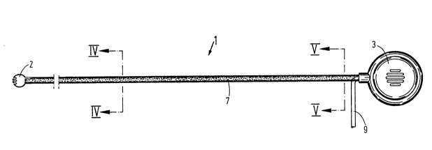
fig. 1 shows a telephone headset according to a first
embodiment of the invention,
fig. 2 shows the telephone headset in fig. 1 in position
for use,
fig. 3 shows a second embodiment of a telephone headset
and in a different position for use,
. ~ .: :
: ~
- , : :.
~ . ~
,: . . . :
2 ~ 7 ~
fig. 4 shows on an enlarged scale a plane cross-sectlon
of f~g. 1 along the llne IV-IV,
fig. 5a shows on an enlarged scale a plane sectlon of
fig. 1 along the line V-V,
fig. 5b shows another configuration of the cross-
sectional profile as shown in fig. 5a,
fig. 6a-6b show examples of telephone headsets according
to the invention in connection with various
constructions of sound reproducers,
fig. 7 shows a third embodiment of the invention, in
which the sound reproducer is placed at a dls-
tance from the one end of the support member,
flg. 8 shows a fourth embodlment of the invention, ln
which a so-called earbud is applied,
fig. 9a-9b show a fifth embodiment of the invention, ln
which an earbud is connected via an assembly
member, and
fig. lOa and lOb show a sixth embodiment of the inven-
tion, ln which a so-called eartip with a
sound hose is applied.
DESCRIPTION OF THE EMBODIMENTS
,
Fig. l shows a telephone headset 1 comprising a mlcrophone
or a sound receiver 2, an elongated support member or ob-
ject 7, a sound reproducer 3, and a wire 9 containing both
the microphone and the sound reproducer wires, usually a
four conduct wire. The microphone 2 and the sound repro-
, .
13al3, 03/06-1992
: ~ , . , , , .;,
,`. . ,, : , , ~ ~ . :
`., - -, : : ~ ~ ~ :
6 ~7~3~.~
ducer 3 are arranged at each their end of the elongated
support member 7, whiah is arranged 80 that the microphone
wlre can be placed herein.
In the embodiment shown in fig. 1 the telephone headset 1
is applicable as an ordinary handset, as known from ordin-
ary telephone apparatus.
The support member 7 is of a material or a combination of
materials or a construction allowing it to be configured in
a substantially inelastical manner by bending. However, any
configuration is reversible on desire. The support member
or ob~ect 7 is simply designed so as to be configurable by
bending at any spot and in any direction and to the effect
that after being bent the member remains stabile, i.e. the
bend is inelast~c.
In figs. 2 and 3 is shown how the telephone headset 1 is
applicable around a person's outer ear, constituting a
; 20 telephone headset, viz. in such a manner that the sound re-
producer is placed at the sound entrance of the outer ear
and in such a manner that the microphone 2 is placed e . g.
- opposite the user's mouth. The configuration applied to thetelephone headset by ordinary bending has been executed by
the user himself. The support member or ob~ect 7 is made of
a material which the user can simply configure as desired
by bending it with his fingers.
. In fig. 2 the telephone headset is shown with the micro-
phone arm appearing below the ear 20 and with the wire 9
likewise led behind the ear, whereas fig. 3 shows how the
microphone arm appears above the ear 20, whereas the wire 9
simply hangs from the ear. Thus, a part 11 of the member 7
extends hidden behind the outer ear 20. The wire 9 is con-
nected to the sound reproducer 3 immediately next to the
con~unction of the support member 7. This is only for
~' 13B13, 03~06-1992
, ' , : : :'
:'::, :. . ~ . : .: ::: ' :' :: '::
~: . ' .:': ,:. ' ' "': . . :
`:` ` "' . . . ' : ~ -:, ' -
' .' ``:' ' ~ '`. ::
i . : ;. ~
7 ~70~6
exempllfication, and there i9 no hlndrance why the wlre 9
should not be connected to the telephone headset anywhere
else.
In the sectional figure in fig. 3 is shown an embodlment of
the support member 7 ln the form of a so-called metal hose,
e.g. a convolute tube consisting of a convolute steel band
or a convolute steel wire 13 and a convolute copper wire 14
wound at a slightly larger diameter than the steel member.
The flexible tube is surrounded by a polyurethane tube 12
which is e.g. shrunk around the metal hose. Hereby a metal
hose is achieved which is flexible in any direction and
remains in the bent position. In the centre of the metal
hose the microphone wire 15 is inserted.
Figs. 4, 5a and 5b show sections of the telephone headset
in fig. 1, figs. 5a and 5b showing different examples of
the cross-sectional profile. In this embodiment the support
member 7 consists of a rubber or plastic tube 10 surround-
ing a central core 8 of a soft metal, e.g. annealed copperor iron wire. Further, the microphone wires 4 have been em-
bedded or inserted. Usually, the plastic or rubber material
10 will be elastically deformable, and the core 8 will be
inelastically deformable. If the central core 8 is of an
electrically conducting material, it may of course be
applied as e.g. microphone wire, in that the central core
may be separated longitudinally in two from each other
electrically insulated conductors. The plastic or rubber
material lO may e.g. be Neopren cell rubber, foam PVC and
similar materials which are fusible or configurable as
desired.
Figs. 6a and 6b show further embodiments of the telephone
headset according to the invention. In fig. 6a is shown an
open supra aural sound reproducer 3 with mounted foam rub-
ber 16. A cast of hard or soft plastic could also be mount-
13EJ13, 03/06-1992
-
-: : ' ` ` :
:':`. ~ `' ' ~ ,
'-, : ' . . :
8 207~fi
ed on the sound reproducer, whlch renders fine acoustlc
connection to the ear, a so-called closed supra aural sound
reproducer; however, this means that the telephone headset
is applicable only by the person in question and only on
the ear of which the cast has been taken.
In fig. 6b is shown another embodiment of a sound repro-
ducer on which is mounted a standard "cast" 17 of foam rub-
ber, soft rubber, plastic or the like, whereby increased
comfort and better acoustic connection between the sound
reproducer and the ear is achieved, but without the ad~ust-
ment being individual for one user or one ear.
In fig. 7 is shown an embodiment in which the support mem-
ber is separated into two areas 7a and 7b, the sound repro-
ducer 3 being fixed to the support member or around the
support member at some distance from its one end by means
of a holder or fitting 21. At the end opposite the micro-
phone 2 a stabilizer 22 is arranged which e.g. may be ball-
shaped as shown, but may be shaped differently. The stabil-
izer which may be made of soft plastic or of the same ma-
terial as the rest of the support member is intended for
supporting behind the ear, e.g. in the same way as the sta-
bilizer of applicant's US patent No. 4,893,344, or in the
same way in which the thickening of a side bar supports
behind the ear. During use, the telephone headset is placed
with the holder or fitting 21 in front of the ear, and so
that the sound reproducer 3 is placed correctly opposite
the ear, whereupon part 7b with the stabilizer 22 is bent
and placed behind the ear, and part 7a of the support mem-
ber constitute~ a microphone bar which may be bent for
suitable positioning of the microphone 2. The stabilizer 22
may also be arranged to render a c0rtain balancing of
weight of the telephone headset. The wire 9 is in fig. 7
shown extending directly from the sound reproducer 3.
13813, 03/06-1992
- . ,
:
. ' ' ` .~
: , . , . : :' '' :
~ :` ' ` . ` ' :
2 ~7 ~,'!3
The embodiment in flg. 8 comprises a through-golng support
member in the same way as the embodiment in fig. 1, but the
wire 9 extends via an opening in the stabilizer 22. A wire
pair 23 for a sound reproducer 24 of the type open intra-
concha extends through the same opening. The sound repro-
ducer 24 comprises a foam rubber cap 25. Such a sound re-
producer construction is also called an "earbud".
Figs. 9a and 9b show other embodimants of the invention
using an "earbud" as a sound reproducer, in which, however,
the sound reproducer is connected to the telephone headset
via a housing 26 or a similar connection member arranged at
a distance from the one end of the support member. The
housing 26 may also be configured in plastic and surround
the support member as shown, but may also be configured
differently. The wire 9 may extend from the housing 26
(fig. 9a) or via the stabilizer 22 (fig. 9b). The housing
26 may contain inactive or active electronic circuit com-
ponents, e.g. for adapting the microphone or the sound re-
producer of the telephone headset to the equlpment or clr-
cuit to which the telephone headset is to be connected.
Figs. lOa and lOb show further embodiments of the telephone
headset according to the invention. In these embodiments
2~ the housing 29 contain the sound reproducer itself or a
miniature loudspeaker from which the sound via a sound hose
27 is transmitted to the sound reproducer 28, a so-called
"eartip", e.g. in the same way as in a behind-the-ear hear-
lng aid. The sound reproducer 28 may be a standard eartip,
e.g. of foam rubber or similar material, but may also com-
prise an individual cast of the user's ear cavity. The wire
9 may extend from the housing 29 (fig. lOa), either in
front of or behind the ear during use, or the wire 9 may
extend through the stabilizer 22 (fig. lOb). In the housing
2g there may in addition to the sound reproducer or a mini-
ature loudspeaker be arranged inactive or active electronic
13313, 03/t~6-1992
- . . ~ ' i , ' : :. .:
',. `'1"' ''.'`',' , ,:
~' . ' , ' ' ,:
lo 2 ~ 7 ~
circuit members, e.g~ amplifiers or impedance adJusting
circuits.
From the above description it will be obvious to a man
skilled in the art that for a sound reproducer any known
type is applicable, e.g. supra aural, supra concha or intra
concha, of open or closed type, or an eartip with a sound
tube of any known type, without deviating from the original
idea of the invention.
The microphone or microphone housing 2 is shown schematic-
ally only. It will be obvious to a man skilled in the art
that any microphone is applicable in the microphone hous-
ing, e.g. a dynamic microphone, an electret microphone, a
ceramic microphone or a magnetic microphone, without there
being any need for principally altering the telephone head-
set according to the invention.
It will be obvious to a man skilled in the art that the
support member 7a, 7b of the telephone headset may be ex-
ecuted or configured with any cross-sectional profile and
any desired variation of cross-sectional area, e.g. gradu-
ally increasing cross-sectional area towards the sound re-
producer, without deviating from the invention. Further, it
is obvious to a man skilled in the art that the support
member may be configured or made of any suitable material
or any suitable composition of materials or construction in
order to achieve the desired characteristics, without devi-
at1ng from the basic prlnc1p1ec of the lnventl~n.
.f
13E113, 03/06-1992
"
~.
' ' ' ~