Note: Descriptions are shown in the official language in which they were submitted.
. ~ 1 2070993
BATTERY HOUSING ~ F.MRLy WITH INTEGRAL
LIMITED TRAVEL GUIDE RAILS
Field of the Invention
This invention relates generally to battery housing
apparatus and more particularly to a battery housing base
with an integral, limited travel, sliding ~h~nnel merhs~ni~m
10 having an indentation disposed between neighhoring guide
rails.
Background of the Invention
1 5
Miniature electronic equipment is often portable in nature,
and, as such, requires a portable source of power such as a
battery. A battery supply may be conveniently ~tt~rhe~l to the
housing of the mini~ture electronic equipment and make
2 0 electronic contact by way of a conventional connector. To make
battery ~h~n~ing easier, mech~ni~m~ have been devised to
enable the user to easily fli~connect the spent battery and
replace it with a freshly charged battery. It has been ~ V~ll
desirable to securely affix the det~h~ble battery to the
2 5 miniature electronic equipment by way of a sliding channel
and l~tching mech~ni~m As the equipment becomes smaller,
however, it has become incre?.~ingly difficult to control the
dimensions of the features critical to the interface between the
battery and the electronic equipment. Critical interface
3 0 features include the sliding ~h~nnel~, latch and battery
contacts.
Typically, battery housings are ~semhlies having a
housing base and a housing cover which are joined to each
2070993
other to encomp~cs electrochçmical cells cont~ine~l within the
~ssemhly. The sliding rh~nnel features are often designed
into the battery housing Pssemhly as a comhin~tion of features
in the housing base and the housing cover. Variation in the
5 ~csemhly process ~tt~rhing the base to the cover sometimes
results in variation in the fiimen~ions of the sliding channels.
Variation in the tlimçn~ions of the sliding ch~nnel~ causes the
position of the latch and battery contacts on the battery housing
to vary relative to the slides. As a result, the battery may not fit
1 0 or function properly when ~ttached to the electronic
equipm~nt, Thus, it would be advantageous to m~nllfact~lre
all the critical interface features as part of the base so that
their ~lim~n~jon~ relative to each other may be controlled.
The difficulty in manufacturing all the critical interface
1 5 features in the battery housing base arises in creating the
guide rails for the sliding rh~nnel~. The sliding channel
usually has three inside surfaces forming a "U" shape. The
guide rails are usually elongated protrusions disposed at
intervals on one of the two parallel side surfaces inside the
2 0 ch~nnel. The bottom surface of the channel is usually
disposed perpendicularly to the two side surfaces. The guide
rails are parallel to the bottom surface. Using conventional
molding processes, the sliding channel~, latch and battery
cont~ct receptacles are molded into the battery housing base
2 5 anticipating a straight pull ejection from the tooling cavity.
The guide rails in the sliding ch~nnels~ however, are position
perpendicularly to the direction of ejection from the tooling
cavity.
One approach that has been considered involves insert
3 0 molding. Using this process, the sides of the sliding lh~nnçl~
including the guide rails are molded separately first then
inserted into a second mold which forms the rem~ining two
sides of the sliding ch~nnel and the complete molded battery
3 207099~
housing base. The problem with this a~loach is that it is both
labor and time intensive to complete the two stage molding
process.
Another a~,oach which has been considered involves
5 cc~molfling. Using this process, the side of the sliding
ch~nnPls including the guide rails are mol~le-1 separately in a
first cycle. One part of the tool is removed and replaced with a
secQn~l part which has the rçm~ining features of the sliding
rh~nnel and the complete battery housing base. A second
1 0 mold cycle is initiated to produce the completed battery
housing base. The problem with this approach is that there
are no ~llt~m~ted comolding tools available which mold the
first stage in a straight pull direction and the second stage in a
pull direction perpendicularly to the first stage pull.
1 5 Developing a speci~li7e~l comolding process for a battery
housing base would be expensive.
Thus, there is a strong need for a battery housing base
with an integral, limited travel, sliding rh~nnel merh?.ni~m
having guide rails which can easily be manufactured, has
20 controlled critical interface rlimp~nRions and has its critical
interface ~imen~ions disassociated from the att~chment of a
battery housing cover.
4 2070g9'3
Sllmm~ry of the Invention
A battery housing ~ssçmhly for portable electronic
eqllipmant having at least first and second mP.t;ng housing
5 portions enclosing electrorhamical cells therebetween. The first
housing portion having at least one ~tt~ching surface by which
the battery housing ~sçmhly is det~rh~hly connected to the
portable electronic equirmsnt. The battery housing assembly
comprises at least one rh~nnel disposed in the att~çhing surface
1 0 of the first housing portion.
At least one rh~nnel further comprises a first surface
~lisrosefl; at least one elongated protrusion on the first surface
and elrtsn-line along the first surface parallel to the att~rhing
surface; and at least one indentation, at least as long as the
1 5 elongated protrusion, disposed in at least a portion of the first
surface adjoined to at least one end of the elongated protrusion.
Brief Description of the Drawings
FIG. 1 is an isometric drawing of a hand-held portable
radiotelephone which may employ the present invention.
FIGS. 2A and 2B are drawings of a battery housing (FIG.
2A) and portable radiotelephone (FIG. 2B) in which the battery
2 5 has been detached from the portable radiotelephone.
FIG. 3 is a view of the m~ting service of the battery housing
base of the battery of FIG. 2A showing the integral latch,
electrical contacts and reduced travel g~ude rails.
FIG. 4 is a cross sectional view in perspective of a portion
3 0 of the battery housing base shown in FIG 3.
FIG. 5 is a cross-sectional view of the battery housing base
and cover of FIG. 2A before they are ~qssemhled to each other.
2(J70993
Description of a Preferred Embodiment
A portable radiotelephone adapted to be used in a cellular
radiotelephone system is shown in FIG. 1. The present
invention may be employed in such a portable radiotelephone
as well as in other mini~tllre electronic eq~ipment The
illustrated portable unit consists of two external portions, a
body portion 102 and a flip elèment portion 104, in addition to a
det~- hAhle battery 105. The drawing of FIG. 1 shows the flip
1 0 element 104 in an "open" position such that a user of the
portable unit may listen via earpiece 106 and may speak into a
microphone 107. A telephone dial, or keypad, 110 consists of a
plurality of buttons numbered one through zero, #, and *, in a
fAmiliAr telephone arrangement. The keypad 110 also has
additional function buttons such as "send", "end", "on/off',
and other buttons associated with telephone number recall.
Since the portable radiotelephone of FIG. 1 is indeed
portable, some source of electrical energy is necessary to power
the electrical functions of this radiotelephone. The source of
2 0 this electrical energy is a battery 105 which is typically
implemented as a rechargeable electrochemical cell or cells.
It is ç~pected that the user will be able to either recharge the
battery while the battery is att~he-l to the radio or detach the
battery from the radio and charge it separately.
2 5 Referring now to FIG. 2A, the configuration of the
det~h~ble battery 105 can be apprehçntle~l in the condition
where the battery 105 is detached from the portable
radiotelephone of FIG. 1. In the preferred embo~3iment of the
present invention, the battery housing consists of two halves, a
3 0 base 300 in FIG. 3 and a cover 202 in FIG. 2A, which are
perm~nently affixed together. A conventional set of
electrochemical battery cells (not shown) may be sandwiched
between and captivated by the two plastic housing portions
6 2070993
which may be secured together to form an integral battery
housing p~k~ee.
An integral latch merhP~ni~m 201 is integrally molded on
the battery housing base. The latch meçh~niRm is molded into
5 the inside half of the plastic housing. To disengage the battery
105 from the portable radiotelephone 102, the latch merh~ni~m
201 is pushed at the portion visible in FIG. 2A thereby causing
a torsion beam (not shown) to rotate and cause a catch (not
shown) to retract from a pocket 212 in the portable
1 0 radiotelephone 102. (The portable radiotelephone 102, in a rear
elevation view with the battery removed, is shown in FIG. 2B).
This action rele?.~es the battery from its locked position and
enables the battery housing 105 to be removed from the portable
radiotelephone 102. The m~tine surface of the portable
1 5 radiotelephone 102 has a pocket or indented slot 212 which is so
formed and positioned that it engages the catch portion of latch
mel~h~ni~m 201 when the battery housing 105 is located in its
fully attached position. The battery housing is thereby locked
in place. Guide rails 213 through 218 extend from a surface of
2 0 the portable radiotelephone housing 102 and are disposed
opposite simil~r guide rails on the battery housing 105. The
guide rails of the battery housing 105 are capt*ated beneath
guide rails 213 through 218 of the portable radiotelephone
housing 102 when the battery housing 105 is in its operational
2 5 (and locked) position. The optional position is, of course, when
elect~cal contacts 225 have contacted mating contacts 325 (not
visible) of the battery housing 105.
Lateral slots 233 and 235 in FIG. 2A on opposite sides of the
battery housing ~semhly 105 are located in a position such
3 0 that the battery alone or the battery and portable
radiotelephone together may slide into a common battery
charging unit and be properly oriented relative to the battery
charging contacts 239.
7 2070g93
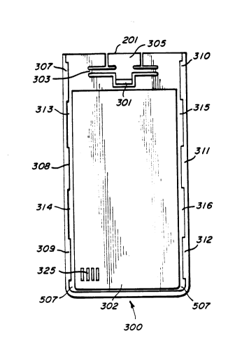
The surface 302 of the battery housing base 300 which
mates to the portable radiotelephone of FIG. 2B i8 shown in the
elevation view of the m~ting surface of FIG. 3. The housing
base 300 generally includes the latch mech~ni~m 210, sliding
chS~nnels 507, battery cont~ct receptacles 325 and in(lçnt~;on~
313 through 316. The latch me~h~nism 201 i8 seen in greater
detail in FIG. 3 and it can be perceived how the catch 301
rotates about the torsion bar 303 when the button portion 305 is
pressed by the user to remove the battery. Such a button
1 0 pressing in a direction out of the plane of the page of FIG. 3
(and into indented area 227 of the portable radiotelephone
housing 102) causes torsion bar 303 to rotate and move catch
301 into the plane of the page of FIG. 3. This motion
disengages the catch 301 from slot 212 (shown in FIG.2B)
1 5 thereby unlocking the battery housing and enabling the user to
slide the battery along g ude rails 307 through 312. Shortened
guide rails 307 through 312, disposed on the parallel surfaces
of each rh~nnel facing each other, with gaps in between each,
enable secure fastening of the battery housing 105 to the
2 0 portable radiotelephone housing 102 the entire length of the
battery housing 105 while allowing a short travel
displ~cement of the battery housing before the battery housing
may be disengaged and removed from the portable
radiotelephone 102. When guide rails 307 through 312 are fully
2 5 disengaged from the portable radiotelephone housing, the
battery electrical contacts 325 are disengaged from the battery
input electrical contacts 225 on the portable radiotelephone
housing. Once guide rails 307 through 312 have moved past
the opposing g~ude rails 213 through 218 on the portable
3 0 radiotelephone housing 102, the battery 105 may be lifted clear
of the portable radiotelephone 102.
In the preferred embo-liment, the guide rails 307 through
312 are bullet shaped (better illustrated in FIG. 4) but in
- 8 20709~3
alternate embo-liment~ they may resemble other shapes to
f ccompli~h the same function. The guide rails 307 through
312 must be elongated and parallel to the ~tt~chin~ surface 302
of the battery housing 300 and their m~tin~ surfaces must be
5 coplanar with the m~tin~ surfaces of the opposing guide rails
213 through 218 on the portable radiotelephone housing 102.
A feature of the l"efelled embo~liment of the present
invention is an in~ant~tion in the gap between two n~iehhoring
guide rails. The battery housing base includes four such
1 0 indentations 313 through 316. In the preferred embo-liment"
the in~l~nt~tions form a slight recessed step in the three
surfaces of the sliding ch~nn~l 507. The in-lerlt~tions may not
be limited to a recessed step; they may also a recessed slope or
any shape which is lower than the plane on which the
1 5 protrusions are disposed. The in~nt~tions have two
purposes. The first purpose is to enable the guide rails 307
through 312 to be manllf~rt~lred as an integral part of the
housing base 300. The man1lf~ctl-ring process uses a single
shot injection, straight pull ejection molding process. This
2 0 manufacturing process is inexpensive and has a fast molding
cycle time. An advantage of molding the guide rails 307
through 312 as part of the battery housing base 300 is that
critical interface rlimP!n~ions between the battery housing base
300 and the portable radiotelephone 102 can be controlled. It is
2 5 important that the relative dimensions between the guide rails
307 through 312, the latch mPrh~niam 201, and the battery
cont~qct receptacles 325 be controlled to ensure proper fit and
function of the battery 105 to the portable radiotelephone
housing 102. Another advantage of having all critical
3 0 dimensions controlled on the battery housing base 300 is that
the critical ~1imen~ions are not affected by the att~hm~nt of
the battery housing cover 202.
- 20~0993
g
The seconA purpose of the intl~nt~t;onc 313 through 316 on
the battery holl~ing base 300 is to enable easy ~csemhly of the
battery housing 105 to the portable radiotelephone housing 102.
The indentations 313 through 316 increase the width of the
5 sliding rh~nnel in the gap between the g ude rails on the
battery housing base 300. The increased width allows the
guide rails 307 through 312 on the portable radiotelephone
housing 102 to be inserted into the gap with less restriction.
The guide rails 307 through 312 on the portable radio telephone
1 0 housing 102 have a bullet shape on their le~Aing ends to glide
off of the recçsse-l steps in the battery housing çhs3nnel
Therefore, a user of a portable radiotelephone can more easily
attach a m~t;ng battery.
Now lefel~ g to FIG. 4, there is shown a cross-sectional
1 5 view in perspective of a portion of the battery housing base 300.
This portion shows in more detail one inAent~tion 314 disposed
in the sliding channel between two guide rails 308 and 309. As
FIG. 4 shows, the indentation is recessed into all three sides of
the sliding ch~nnel. The length of the indentation 314 is at
2 0 least as long as the length of the guide rail 309. The depth of
the recessed step on all three sides of the slide is typically .07
mm. The flat end of the guide rail 308 adjoins the indentation
314. As previously mentioned, the indentation 314 enables the
guide rails 307 through 312 to be molded as an integral part of
2 5 the battery housing base 300. In general, the indentations
clear the gap between the guide rails allowing the part of the
tool creating the guide rails to slide into the gap. The direction
of the sli~ing action is from guide rail 308 to guide rail 309.
Due to the sliding action direction, the guide rail 308 must
3 0 adjoin the in(lent~t;r,n 314 so the sliding tool may clear the
guide rail 308. Once the tool is clear of the guide rails, the
battery housing base is ejected from the tool cavity. The sliding
- 10 207û993
and ejecting steps of the t~oling process is Rimil~r to the battery
housing 105 det~rhine from the portable radiotelephone 102.
The integral guide rails are molded using a four step
process once the plastic material has been shot into the mold
and the mold has cooled down. In the preferred embo~liment
the housing portions are molded from polycarbonate plastic or
fiimil:~r material. The first step is to remove the part of the
tool creating the indentation.` The second step is to slide the
part of the tool creating the guide rails appro~im~tçly 22 mm.
1 0 This sli~ing motion positions the part of the tool creating the
guide rails 308 and 309 into the gap. The indentation 314
ensures that the sliding action of the sliding tool will not bind
or catch a part of the housing base 300 creating the sliding
r~h~nnel in the gap. Typically, the sliding tool may bind when
1 5 the plastic shrinks before the tool can slide into the gap. Also,
the sliding tool can catch on flash, created by a tool adjacent to
the sliding tool, as the tool slides. The indentation çlimin~tes
both of these problemR. Once the tool creating the guide rails
has slid into the gap, the third step is to open the mold up and
2 0 the fourth step is to eject the battery housing base 300 from the
tool cavity.
Now referring to FIG. 5, there is shown a cross-sectional
view of the battery housing base 300 and the battery housing
cover 202 before their attached to each other. In the ~lefelled
2 5 embodiment of the present invention, the base 300is ~tt?.~hed
to the cover 202 using an ultrasonic welding process. Using
this process, a pointed protrusion 501 on the battery housing
base 300 is inserted into a groove 503 in the battery housing
cover 202. Once inserted an ultrasonic horn applies energy to
3 0 the battery housing base 300 which causes the protrusion 501 to
fuse to the groove 503. This operation l.elrol-lls a secure and
permanent bond between the base 300 and the cover 202. A
feature of the preferred embodiment of the present invention is
1 1 2070993
that the ~tt~r.hm~nt method between the base 300 and the cover
202 does not alter the form, fit or function of the guide rails 309
within the sli~ing ch~nnel 507. For the user of a portable
radiotelephone, this feature tr~n~l~t~s into a battery that will
5 always have a proper form, fit and function of the guide rails
within the sli(ling rh~nnel~ latch mech~nism and battery
cont~rtfi to the portable radiotelephone housing 102.
Therefore, a battery housing base having an integral,
limited travel, sliding ch~nnpl mech~niRm with guide rails to
1 0 provide short travel between the engaged and disengaged
position of the battery housing on a portable radiotelephone has
been shown and described. The housing base is easily
manllf~rtllred using a single shot injection, single pull
ejection molding process. Critical interface limenRions on the
15 housing base are controlled and liR~ssociated from the
~tt~chm~nt of the battery housing cover.
What is claimed is: