Note: Descriptions are shown in the official language in which they were submitted.
20710~4
Circular saw blade and process for the production thereof
The invention concerns a circular saw blade with a rotation
axis and a flat annular element, arranged around the rotation
axis, which is provided with teeth on its outer edge.
The invention further concerns a process for the production
of a circular saw blade using a plane, flat annular element
that is provided with teeth on its periphery.
A circular saw blade of the aforesaid type is generally
known, for example from WO 88/02683.
The known circular saw blade is, like other known circular
saw blades, designed so that it is thickened in the region
near the axis, and is flatter at its periphery. Known
circular saw blades generally have a plane radial defining
~ - 2 - 20~ 10~ 4
surface, but occasionally they are also symmetrical with
respect to a radial center plane, and thus become thicker on
either side of the radial center plane.
It is generally desirable in saw technology, however, to
make saw kerfs as narrow as possible in order to maximize
wood yield by minimizing the volume of sawdust. This is
especially true if a plurality of thin boards is to be cut
out of a piece of lumber, since then the kerf width is an
important factor in the wood yield.
The demand for the thinnest possible kerf necessarily leads
to especially thin circular saw blades. One the one hand,
however, circular saw blades cannot be made arbitrarily
thin, since otherwise there would be stability problems,
especially if one simultaneously wishes to have high feed
speeds or cutting speeds in order to cut the largest
possible quantity of wood products in a certain period of
time. Specifically, as the feed or cutting speed is raised,
the radial load on the circular saw blade simultaneously
increases, with the result that the ensuing stability
problems become greater, the thinner the circular saw blade.
On the other hand, it has been proposed in the aforesaid WO
88/02683 that circular saw blades be used together with
"separator elements." This is understood to mean an element
that is stationary with respect to the rotating circular saw
blade, that extends to a point close to the teeth of the
circular saw blade, and that bends the separated side board
out of the separation plane immediately after passage of the
teeth, and removes it from engagement with the circular saw
blade.
~ 3 ~ 207 105~
With circular saw blades of this kind that have a separator
element, it is indeed possible to reduce further the
mechanical stress on circular saw blades, but this again
comes close to the limits of feasibility.
The underlying object of the invention is therefore to
indicate a circular saw blade and a process for the
production thereof, so as to make available a circular saw
blade that satisfies even higher criteria for stability on
the one hand, and thinness on the other hand.
With reference to the circular saw blade mentioned earlier,
this object is achieved, according to the invention, by the
fact that the annular element has a hollow conical shape.
The object underlying the invention is completely achieved
in this manner because the hollow conical shape of the
annular element produces a considerable increase in
stability, since a hollow conical object presents much
greater resistance to a radial load and does not deflect as
easily as a thin saw blade arranged in a radial plane.
It is especially preferred if the hollow conical annular
element has an angle of inclination between 0.1 and 2 .
The advantage of this feature is that on the one hand the
desired increase in stability is achieved, and on the other
hand there is only an imperceptible enlargement in the axial
thickness of the saw blade.
It is furthermore especially preferred if the annular
element is fastened in a concentric, cone-shaped su~otL.
20710~
The advantage of this feature is that all the elements
required for fastening and drive purposes can be provided in
a support, while the annular element is merely bolted on in
the edge region of the support. This feature also has the
advantage that when wear occurs on the teeth, only the
annular element needs to be replaced, while the support can
be reused after being fitted with a new annular element.
Lastly, it is especially preferred if the annular element
adjoins a stationary separator element, in such a way that a
side piece separated from a main piece by the circular saw
blade is bent outward from the separation plane and is
distanced from the circular saw blade after the teeth pass.
This application of the circular saw blade according to the
invention is especially suitable because in a circular saw
with a separator element, an angle is created in any case
between the main piece and the separated side piece, thus
making available a wedge-shaped space for the hollow conical
annular element. In this application, the angle of
inclination of the hollow cone can therefore ~e pushed to
the upper limit of what is feasible and desirable.
According to the aforesaid process, the annular element is
bolted into a concentric, conical support and thereby
deformed into a hollow conical shape.
The advantage of this feature is that it is essentially
possible to use commercially available annular elements, in
which the hollow conical shape is generated only by bolting
into the support. This is easily possible in mechanical
terms, since (as mentioned), the annular elements used are
made as thin as possible.
2071054
In this case it is especially preferred if the annular
element is rolled, prior to being bolted in, along circles
concentric with its axis of rotation.
The advantage of this feature is that the application of
more or less rolled annular zones onto the annular element
makes it easier for the annular element to "fold" from its
original flat position into the final hollow conical
position after it is bolted into the support.
Further advantages are evident from the description and the
attached drawings.
It is understood that the features described above and those
yet to be explained below can be used not only in the
particular combination given, but also in other combinations
or in isolation, without leaving the context of the present
invention .
An exemplary embodiment of the invention is depicted in the
drawing and will be explained in more detail in the
description which follows.
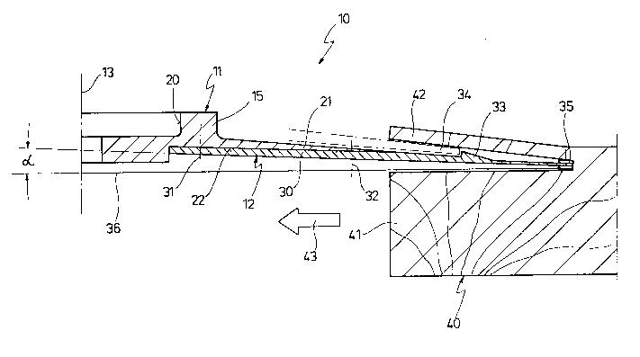
The single Figure shows a radial section through an
exemplary embodiment of a circular saw blade according to
the invention.
In the Figure, 10 designates the totality of a circular saw
blade, which essentially consists of a support 11 and a thin
blade 12. When installed, the circular saw blade 10 can
rotate about a common axis 13 of the support 11 and blade
12.
- 6 - 207 10~ ~
The support 11 essentially has the function of retaining the
blade 12 and attaching it to a drive shaft in a suitable
manner. For this purpose, the support 11 has a central
flange 15 and a suitable hole 20, so the support 11 with the
blade 12 can be fastened onto a drive shaft of a circular
saw.
Towards the outside, the support 11 merges into a flat edge
region 21 which is inclined with respect to a radial plane
by, for example, a few degrees.
One particularity of the support 11 is the fact that its
underside 22 is hollowed out into a conical shape. The angle
of inclination of the cone with respect to a radial plane is
labeled a in the Figure. In practice, angle a can be between
0.1 and a few degrees, preferably approximately 1 . With a
saw blade diameter on the order of, for example, 60~ mm,
this results in a cone height at the axis 13 of between 0.5
and 5 mm.
The blade 12 is bolted to the support 11 at several points,
as indicated by the threaded joints 31 and 32.
At the point where the periphery of the blade 12 extends
beyond the flat edge region 21 of the support 11, it is
provided with an axially projecting edge 33. The edge 33
serves, in a known manner, to constitute the transition to a
stationary separator element 34 which is immovable at least
with respect to the rotating circular saw blade 10.
At its outer periphery, the blade 12 is provided in a known
manner with teeth 35, with together define a separation
plane 36.
- 7 - 2071 05 ~
The circular saw blade 1~ is preferably used to divide up a
piece of lumber 40 by separating a side piece 42, for
example a side board, from a main piece 41. For this
purpose, the piece of lumber 40 and the circular saw blade
10 are pushed towards one another in the direction of an
arrow 43. Usually the circular saw blade 10 is located on a
stationary circular saw, and the piece of lumber 40 is
advanced in the direction of the arrow 43.
As the side piece 42 is separated it is deflected, after the
teeth 35 pass, onto the separator element 34 by the edge 33,
so that the side piece 42 from that point on is no longer in
mechanical contact with the rotating circular saw blade 10.
Since the blade 12 of the circular saw blade 10 is conically
deformed, the conical angle represents more or less a
continuation of the separator element 34 which also runs
obliquely; or, in other words, the hollow cone formed by the
blade 12 is, in one configuration of a circular saw blade 10
with separator element 34, capable of penetrating into the
gap that is formed in any case between the side piece 42 and
main piece 41.
It has already been mentioned that the blade 12 is bolted
from below against the conical underside 22 of the support
11 .
This is preferably done by reshaping a blade 12, which in
its original state is plane, into a hollow conical shape by
bolting it onto the conical underside 22. The reason this is
possible is because (in contrast to the non-scale
representation in the drawing) the blade 12 is very thin and
can therefore be reshaped without excessive reshaping
stresses.
20710~
- 8 -
To promote this reshaping process, a further embodiment of
the invention provides for the blade 12 to be rolled while
it is being manufactured, by rolling the blade 12 along
concentric circular tracks around the axis 13. This then
results in annular zones of different structure, with the
consequence that when the initially plane blade 12 is bolted
on, it "folds" relatively easily into a conical shape.