Language selection

Search

Patent 2071282 Summary

Third-party information liability

Some of the information on this Web page has been provided by external sources. The Government of Canada is not responsible for the accuracy, reliability or currency of the information supplied by external sources. Users wishing to rely upon this information should consult directly with the source of the information. Content provided by external sources is not subject to official languages, privacy and accessibility requirements.

Claims and Abstract availability

Any discrepancies in the text and image of the Claims and Abstract are due to differing posting times. Text of the Claims and Abstract are posted:

  • At the time the application is open to public inspection;
  • At the time of issue of the patent (grant).
(12) Patent: (11) CA 2071282
(54) English Title: ELECTRIC CABLE TERMINAL WITH BUILT-IN MARKING SUPPORT
(54) French Title: BORNE DE CONNEXION A SUPPORT DE MARQUAGE INCORPORE
Status: Expired and beyond the Period of Reversal
Bibliographic Data
(51) International Patent Classification (IPC):
  • H01R 11/12 (2006.01)
  • G09F 3/20 (2006.01)
  • H01R 11/11 (2006.01)
  • H01R 13/46 (2006.01)
(72) Inventors :
  • PIANA, IVANA (Italy)
  • PIANA, SILVANO (Italy)
(73) Owners :
  • GRAFOPLAST S.P.A.
(71) Applicants :
  • GRAFOPLAST S.P.A. (Italy)
(74) Agent: MARKS & CLERK
(74) Associate agent:
(45) Issued: 2000-10-03
(22) Filed Date: 1992-06-15
(41) Open to Public Inspection: 1993-08-29
Examination requested: 1997-06-12
Availability of licence: N/A
Dedicated to the Public: N/A
(25) Language of filing: English

Patent Cooperation Treaty (PCT): No

(30) Application Priority Data:
Application No. Country/Territory Date
GE92U000013 (Italy) 1992-02-28

Abstracts

English Abstract


A terminal includes a metal part, one end of which is to be
connected to a binding post of electrical equipment, and
the other end of which is shaped as a ring with an
insulating coating. A sleeve mounted inside this
insulating coating has an extension in which a plurality of
marking elements are received. The sleeve and its
extension are directly molded on the terminal.


Claims

Note: Claims are shown in the official language in which they were submitted.

The embodiments of the invention in which an exclusive
property or privilege is claimed are defined as follows:
1. An electrical terminal for a cable to be marked,
comprising:
an electrically conductive member extending along a
longitudinal axis between one end for connection to an
electrical device, and an opposite end for connection to an
electrical cable to be marked
an electrically insulating, tubular coating surrounding and
fixedly mounted on said opposite end of the conductive
member, and having a tubular end region extending along the
longitudinal axis away from said opposite end of the
conductive member; and
a marking sleeve having a tubular mounting portion fixedly
and non-rotatably mounted within the tubular end region of
the coating to constitute a non-detachable assembly, said
marking sleeve being constituted of a molded synthetic
plastic material and having an extension integrally molded
with the sleeve, said extension extending along the
longitudinal axis away from said opposite end of the
conductive member.
2. The terminal according to claim 1, wherein said
one end of the conductive member has a ring shape.
3. The terminal according to claim 1, wherein said
one end of the conductive member has a fork shape.

4. The terminal according to claim 1, wherein said
one end of the conductive member has a plug shape.
5. The terminal according to claim 1, wherein said
one end of the conductive member has a plug-socket shape.
6. The terminal according to any one of claims 1 to
5, wherein said opposite end of the conductive member has
curved walls for fixedly engaging the cable to be marked.
7. The terminal according to any one of claims 1 to
6, wherein the tubular mounting portion is coaxial with the
tubular end region of the coating, said tubular mounting
portion and said tubular end region both having hollow
interiors for insertion of the cable to be marked.
8. The terminal according to any one of claims 1 to
7, wherein the conductive member is radially offset from
the longitudinal axis.
9. The terminal according to any one of claims 1 to
8, wherein the conductive member has a generally planar
body portion intermediate said one end and said opposite
end, and wherein the extension extends in a plane generally
parallel to the planar body portion.
10. The terminal according to any one of claims 1 to
8, wherein the conductive member has a generally planar
body portion intermediate said one end and said opposite

end, and wherein the extension extends in a plane generally
normally of the planar body portion.
11. The terminal according to any one of claims 1 to
10, further comprising cable marking means mounted on the
extension.
12. The terminal according to claim 11, wherein the
cable marking means includes a plurality of cable marking
elements, each having a code thereon.
13. The terminal according to claim 11 or 12, wherein
the extension has an interior recess; and wherein the cable
marking means is mounted within the recess.
14. The terminal according to any one of claims 1 to
13, wherein the marking sleeve and the extension are molded
of plastic material which is transparent.
15. The terminal according to any one of claims 1 to
14, wherein the marking sleeve and the extension are molded
directly on the tubular end region of the coating.

Description

Note: Descriptions are shown in the official language in which they were submitted.


CA 02071282 2000-02-16
ELECTRIC CABLE TERMINAL WITH
BUILT-IN MARKING SUPPORT
Terminals for connecting electric cables or leads to the
binding post of various electric control and operating
units are generally known. These terminals essentially
consist of a conductive metal element having a sleeve or
lug at one end and a connecting device at the other end.
The sleeve is wrapped in insulating material, usually
opaque plastic and receives one end of the lead. This
sleeve is properly deformed so as to pinch the lead and
prevent it from slipping out. The end of the joint or
connector to the terminal of the equipment may be shaped
according to need, for instance as a ring, fork or plug,
male-female (called "Faston"'n") and so on.
There are known for instance terminals according to FR-A-
1321537 and EP-A-029554, in which the terminal is
manufactured in separate elements to be assembled. There
are also known terminals, according to EP-A-0251054, which
is formed by a metallic element wrapped in insulating
material presenting a support for the marking device and
according to DE-A-3107083, which presents a marking support
inserted by clutch on the insulating material.
In this application we refer to the known terminals,
commonly used, which, as above clarified, present only the
metal element and the insulating element without marking
support.
1

CA 02071282 2000-02-16
These known terminals are not designed for marking and the
cables must therefore be marked, irrespective of the
installation mode of the terminal. This means a loss of
time during wiring and marking of the electric
installations.
This invention has the aim to fit each known terminal with
a suitable support, apt to receive the marking elements
which will identify the terminal and hence the related
cable. Thus, the cable code can be directly applied as
soon as the terminal is secured to the cable, without
further need for marking the cable.
Accordingly, the present invention relates to an electrical
terminal for a cable to be marked, comprising an
electrically conductive member extending along a
longitudinal axis between one end for connection to an
electrical device, and an opposite end for connection to an
electrical cable to be marked. An electrically insulating,
tubular coating surrounds and is fixedly mounted on the
opposite end of the conductive member, and has a tubular
end region extending along the longitudinal axis away from
the opposite end of the conductive member. A marking
sleeve, having a tubular mounting portion, islfixedly and
non-rotatably mounted within the tubular end region of the
coating to constitute a non-detachable assembly. The
marking sleeve is constituted of a molded synthetic plastic
material and has an extension integrally molded with the
sleeve. The extension extends along the longitudinal axis
away from the opposite end of the conductive member.
2

CA 02071282 2000-02-16
The subject matter of this invention is illustrated in the
enclosed drawing, in which:
FIG. 1 shows a longitudinal sectional view of a known ring
shaped terminal;
FIG. 2 shows a side elevational view of the known terminal
illustrated in FIG. 1;
FIG. 3 shows a longitudinal sectional view of the terminal
with a support for the marking elements according to this
invention, placed on the plane of the coupling ring;
FIG. 4 shows a side elevational view of the terminal
illustrated in FIG. 3;
FIG. 5 shows a side elevational view of the terminal
illustrated in FIG. 3 with an extension to lodge the
marking elements rotated by 90° with respect to the
embodiment in FIGS. 3 and 4;
FIG. 6 shows a front elevational view of the terminal
illustrated in FIG. 5;
The FIGS. 7, 8, and 9 show a side elevational view of
exemplified terminals according to this invention,
respectively with a fork shaped, plug and Faston type end.
With reference to FIG. 1 and 2, the known terminal consists
of a metal portion 1 having a shaped end 2 according to the
type of connection to be made with the equipment, i.e.
3

CA 02071282 2000-02-16
ring, fork, plug or Faston type. The opposite end 3 of the
metal portion is ring shaped and covered by a insulating
material 4, usually in non transparent and strong plastic.
According to known procedures, the end of the conductor
cable from which the insulation has been removed, is
threaded in the ring 3 of the metal part 1 where it is
trapped by pinching the ring so as to obtain a stable joint
between terminal and cable.
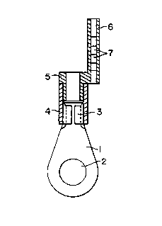
According to the invention illustrated in FIGS. 3 and 4, a
sleeve 5 featuring on one peripheral surface an extension
6, lengthwise to the terminal, in which to house the
marking elements 7, is formed at the external extension of
the ring shaped end 3 of the metal portion 1 and partially
inside the insulating coating 4.
This sleeve 5 and its extension 6 are obtained by direct
injection molding on the known terminal, so as to include
all parts and form an irremovable and non-detachable
assembly.
The extension 6 of the sleeve should be preferably recess
shaped, i.e. as a tube in which to lodge, in known manner,
the marking codes consisting of marking elements or tags 7.
This means that the extension must be transparent so that
the marking elements will be clearly legible and for this
reason, the whole sleeve 5 and its extension 6 are in
transparent plastic material.
4

CA 02071282 2000-02-16
However, this does not exclude that the extension 6 may be
ferrule shaped onto which the marking rings or tags are
applied. This embodiment has, however, the drawback of not
providing protection for the marking elements which may
become illegible in the course of time, while on the other
hand, the extension need no longer be in transparent
material.
In FIGS. 3 and 4, the extension 6 is located on one side of
the terminal and on the same plane with its end 2 hooked
onto the binding post, but this is only for exemplification
since the extension 6 may be located anywhere with respect
to the terminal. For instance, in FIGS. 5 and 6, the
extension is located above the terminal at a right angle to
the position illustrated in FIGS. 3 and 4.
As already explained, the end 2 of the metal part 1 of the
terminal may be differently shaped according to the
connection to be made and the subject matter of this
invention may be directly and obviously extended to any and
all ring (FIG. 5), fork (FIG. 7), plug (FIG. 8), male-
female (FIG. 9) shaped and other solutions.
According to this invention, the terminal has therefore its
own marker support so as to facilitate wiring of the
connections and to eliminate the need for single cable or
wire marking.
5

Representative Drawing
A single figure which represents the drawing illustrating the invention.
Administrative Status

2024-08-01:As part of the Next Generation Patents (NGP) transition, the Canadian Patents Database (CPD) now contains a more detailed Event History, which replicates the Event Log of our new back-office solution.

Please note that "Inactive:" events refers to events no longer in use in our new back-office solution.

For a clearer understanding of the status of the application/patent presented on this page, the site Disclaimer , as well as the definitions for Patent , Event History , Maintenance Fee  and Payment History  should be consulted.

Event History

Description Date
Time Limit for Reversal Expired 2010-06-15
Letter Sent 2009-06-15
Inactive: IPC from MCD 2006-03-11
Grant by Issuance 2000-10-03
Inactive: Cover page published 2000-10-02
Pre-grant 2000-06-28
Inactive: Final fee received 2000-06-28
Notice of Allowance is Issued 2000-04-17
Letter Sent 2000-04-17
Inactive: Approved for allowance (AFA) 2000-03-30
Amendment Received - Voluntary Amendment 2000-02-16
Inactive: S.30(2) Rules - Examiner requisition 1999-12-01
Amendment Received - Voluntary Amendment 1998-03-31
Inactive: Application prosecuted on TS as of Log entry date 1997-09-22
Letter Sent 1997-09-22
Inactive: Status info is complete as of Log entry date 1997-09-22
All Requirements for Examination Determined Compliant 1997-06-12
Request for Examination Requirements Determined Compliant 1997-06-12
Application Published (Open to Public Inspection) 1993-08-29

Abandonment History

There is no abandonment history.

Maintenance Fee

The last payment was received on 2000-06-05

Note : If the full payment has not been received on or before the date indicated, a further fee may be required which may be one of the following

  • the reinstatement fee;
  • the late payment fee; or
  • additional fee to reverse deemed expiry.

Please refer to the CIPO Patent Fees web page to see all current fee amounts.

Fee History

Fee Type Anniversary Year Due Date Paid Date
Request for examination - standard 1997-06-12
MF (application, 6th anniv.) - standard 06 1998-06-15 1998-05-12
MF (application, 7th anniv.) - standard 07 1999-06-15 1999-05-04
MF (application, 8th anniv.) - standard 08 2000-06-15 2000-06-05
Final fee - standard 2000-06-28
MF (patent, 9th anniv.) - standard 2001-06-15 2001-04-26
MF (patent, 10th anniv.) - standard 2002-06-17 2002-06-03
MF (patent, 11th anniv.) - standard 2003-06-16 2003-06-04
MF (patent, 12th anniv.) - standard 2004-06-15 2004-06-01
MF (patent, 13th anniv.) - standard 2005-06-15 2005-04-25
MF (patent, 14th anniv.) - standard 2006-06-15 2006-05-01
MF (patent, 15th anniv.) - standard 2007-06-15 2007-04-25
MF (patent, 16th anniv.) - standard 2008-06-16 2008-05-30
Owners on Record

Note: Records showing the ownership history in alphabetical order.

Current Owners on Record
GRAFOPLAST S.P.A.
Past Owners on Record
IVANA PIANA
SILVANO PIANA
Past Owners that do not appear in the "Owners on Record" listing will appear in other documentation within the application.
Documents

To view selected files, please enter reCAPTCHA code :


To view images, click a link in the Document Description column. To download the documents, select one or more checkboxes in the first column and then click the "Download Selected in PDF format (Zip Archive)" or the "Download Selected as Single PDF" button.

List of published and non-published patent-specific documents on the CPD .

If you have any difficulty accessing content, you can call the Client Service Centre at 1-866-997-1936 or send them an e-mail at CIPO Client Service Centre.


Document
Description 
Date
(yyyy-mm-dd) 
Number of pages   Size of Image (KB) 
Cover Page 2000-09-15 1 24
Representative drawing 2000-09-15 1 3
Representative drawing 1998-10-15 1 6
Cover Page 1993-12-03 1 13
Drawings 1993-12-03 1 32
Description 1993-12-03 5 129
Abstract 1993-12-03 1 14
Claims 1993-12-03 2 37
Description 2000-02-16 5 178
Claims 2000-02-16 3 93
Abstract 2000-02-16 1 13
Drawings 2000-02-16 2 26
Acknowledgement of Request for Examination 1997-09-22 1 178
Commissioner's Notice - Application Found Allowable 2000-04-17 1 164
Maintenance Fee Notice 2009-07-27 1 171
Correspondence 1993-06-10 1 31
Correspondence 2000-06-28 1 31
Fees 1996-03-29 1 55
Fees 1997-05-12 1 63
Fees 1995-04-13 1 54
Fees 1994-04-20 1 56