Sélection de la langue

Search

Sommaire du brevet 2071282 

Énoncé de désistement de responsabilité concernant l'information provenant de tiers

Une partie des informations de ce site Web a été fournie par des sources externes. Le gouvernement du Canada n'assume aucune responsabilité concernant la précision, l'actualité ou la fiabilité des informations fournies par les sources externes. Les utilisateurs qui désirent employer cette information devraient consulter directement la source des informations. Le contenu fourni par les sources externes n'est pas assujetti aux exigences sur les langues officielles, la protection des renseignements personnels et l'accessibilité.

Disponibilité de l'Abrégé et des Revendications

L'apparition de différences dans le texte et l'image des Revendications et de l'Abrégé dépend du moment auquel le document est publié. Les textes des Revendications et de l'Abrégé sont affichés :

  • lorsque la demande peut être examinée par le public;
  • lorsque le brevet est émis (délivrance).
(12) Brevet: (11) CA 2071282
(54) Titre français: BORNE DE CONNEXION A SUPPORT DE MARQUAGE INCORPORE
(54) Titre anglais: ELECTRIC CABLE TERMINAL WITH BUILT-IN MARKING SUPPORT
Statut: Périmé et au-delà du délai pour l’annulation
Données bibliographiques
(51) Classification internationale des brevets (CIB):
  • H01R 11/12 (2006.01)
  • G09F 3/20 (2006.01)
  • H01R 11/11 (2006.01)
  • H01R 13/46 (2006.01)
(72) Inventeurs :
  • PIANA, IVANA (Italie)
  • PIANA, SILVANO (Italie)
(73) Titulaires :
  • GRAFOPLAST S.P.A.
(71) Demandeurs :
  • GRAFOPLAST S.P.A. (Italie)
(74) Agent: MARKS & CLERK
(74) Co-agent:
(45) Délivré: 2000-10-03
(22) Date de dépôt: 1992-06-15
(41) Mise à la disponibilité du public: 1993-08-29
Requête d'examen: 1997-06-12
Licence disponible: S.O.
Cédé au domaine public: S.O.
(25) Langue des documents déposés: Anglais

Traité de coopération en matière de brevets (PCT): Non

(30) Données de priorité de la demande:
Numéro de la demande Pays / territoire Date
GE92U000013 (Italie) 1992-02-28

Abrégés

Abrégé anglais


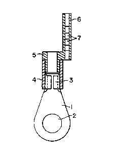
A terminal includes a metal part, one end of which is to be
connected to a binding post of electrical equipment, and
the other end of which is shaped as a ring with an
insulating coating. A sleeve mounted inside this
insulating coating has an extension in which a plurality of
marking elements are received. The sleeve and its
extension are directly molded on the terminal.

Revendications

Note : Les revendications sont présentées dans la langue officielle dans laquelle elles ont été soumises.


The embodiments of the invention in which an exclusive
property or privilege is claimed are defined as follows:
1. An electrical terminal for a cable to be marked,
comprising:
an electrically conductive member extending along a
longitudinal axis between one end for connection to an
electrical device, and an opposite end for connection to an
electrical cable to be marked
an electrically insulating, tubular coating surrounding and
fixedly mounted on said opposite end of the conductive
member, and having a tubular end region extending along the
longitudinal axis away from said opposite end of the
conductive member; and
a marking sleeve having a tubular mounting portion fixedly
and non-rotatably mounted within the tubular end region of
the coating to constitute a non-detachable assembly, said
marking sleeve being constituted of a molded synthetic
plastic material and having an extension integrally molded
with the sleeve, said extension extending along the
longitudinal axis away from said opposite end of the
conductive member.
2. The terminal according to claim 1, wherein said
one end of the conductive member has a ring shape.
3. The terminal according to claim 1, wherein said
one end of the conductive member has a fork shape.

4. The terminal according to claim 1, wherein said
one end of the conductive member has a plug shape.
5. The terminal according to claim 1, wherein said
one end of the conductive member has a plug-socket shape.
6. The terminal according to any one of claims 1 to
5, wherein said opposite end of the conductive member has
curved walls for fixedly engaging the cable to be marked.
7. The terminal according to any one of claims 1 to
6, wherein the tubular mounting portion is coaxial with the
tubular end region of the coating, said tubular mounting
portion and said tubular end region both having hollow
interiors for insertion of the cable to be marked.
8. The terminal according to any one of claims 1 to
7, wherein the conductive member is radially offset from
the longitudinal axis.
9. The terminal according to any one of claims 1 to
8, wherein the conductive member has a generally planar
body portion intermediate said one end and said opposite
end, and wherein the extension extends in a plane generally
parallel to the planar body portion.
10. The terminal according to any one of claims 1 to
8, wherein the conductive member has a generally planar
body portion intermediate said one end and said opposite

end, and wherein the extension extends in a plane generally
normally of the planar body portion.
11. The terminal according to any one of claims 1 to
10, further comprising cable marking means mounted on the
extension.
12. The terminal according to claim 11, wherein the
cable marking means includes a plurality of cable marking
elements, each having a code thereon.
13. The terminal according to claim 11 or 12, wherein
the extension has an interior recess; and wherein the cable
marking means is mounted within the recess.
14. The terminal according to any one of claims 1 to
13, wherein the marking sleeve and the extension are molded
of plastic material which is transparent.
15. The terminal according to any one of claims 1 to
14, wherein the marking sleeve and the extension are molded
directly on the tubular end region of the coating.

Description

Note : Les descriptions sont présentées dans la langue officielle dans laquelle elles ont été soumises.


CA 02071282 2000-02-16
ELECTRIC CABLE TERMINAL WITH
BUILT-IN MARKING SUPPORT
Terminals for connecting electric cables or leads to the
binding post of various electric control and operating
units are generally known. These terminals essentially
consist of a conductive metal element having a sleeve or
lug at one end and a connecting device at the other end.
The sleeve is wrapped in insulating material, usually
opaque plastic and receives one end of the lead. This
sleeve is properly deformed so as to pinch the lead and
prevent it from slipping out. The end of the joint or
connector to the terminal of the equipment may be shaped
according to need, for instance as a ring, fork or plug,
male-female (called "Faston"'n") and so on.
There are known for instance terminals according to FR-A-
1321537 and EP-A-029554, in which the terminal is
manufactured in separate elements to be assembled. There
are also known terminals, according to EP-A-0251054, which
is formed by a metallic element wrapped in insulating
material presenting a support for the marking device and
according to DE-A-3107083, which presents a marking support
inserted by clutch on the insulating material.
In this application we refer to the known terminals,
commonly used, which, as above clarified, present only the
metal element and the insulating element without marking
support.
1

CA 02071282 2000-02-16
These known terminals are not designed for marking and the
cables must therefore be marked, irrespective of the
installation mode of the terminal. This means a loss of
time during wiring and marking of the electric
installations.
This invention has the aim to fit each known terminal with
a suitable support, apt to receive the marking elements
which will identify the terminal and hence the related
cable. Thus, the cable code can be directly applied as
soon as the terminal is secured to the cable, without
further need for marking the cable.
Accordingly, the present invention relates to an electrical
terminal for a cable to be marked, comprising an
electrically conductive member extending along a
longitudinal axis between one end for connection to an
electrical device, and an opposite end for connection to an
electrical cable to be marked. An electrically insulating,
tubular coating surrounds and is fixedly mounted on the
opposite end of the conductive member, and has a tubular
end region extending along the longitudinal axis away from
the opposite end of the conductive member. A marking
sleeve, having a tubular mounting portion, islfixedly and
non-rotatably mounted within the tubular end region of the
coating to constitute a non-detachable assembly. The
marking sleeve is constituted of a molded synthetic plastic
material and has an extension integrally molded with the
sleeve. The extension extends along the longitudinal axis
away from the opposite end of the conductive member.
2

CA 02071282 2000-02-16
The subject matter of this invention is illustrated in the
enclosed drawing, in which:
FIG. 1 shows a longitudinal sectional view of a known ring
shaped terminal;
FIG. 2 shows a side elevational view of the known terminal
illustrated in FIG. 1;
FIG. 3 shows a longitudinal sectional view of the terminal
with a support for the marking elements according to this
invention, placed on the plane of the coupling ring;
FIG. 4 shows a side elevational view of the terminal
illustrated in FIG. 3;
FIG. 5 shows a side elevational view of the terminal
illustrated in FIG. 3 with an extension to lodge the
marking elements rotated by 90° with respect to the
embodiment in FIGS. 3 and 4;
FIG. 6 shows a front elevational view of the terminal
illustrated in FIG. 5;
The FIGS. 7, 8, and 9 show a side elevational view of
exemplified terminals according to this invention,
respectively with a fork shaped, plug and Faston type end.
With reference to FIG. 1 and 2, the known terminal consists
of a metal portion 1 having a shaped end 2 according to the
type of connection to be made with the equipment, i.e.
3

CA 02071282 2000-02-16
ring, fork, plug or Faston type. The opposite end 3 of the
metal portion is ring shaped and covered by a insulating
material 4, usually in non transparent and strong plastic.
According to known procedures, the end of the conductor
cable from which the insulation has been removed, is
threaded in the ring 3 of the metal part 1 where it is
trapped by pinching the ring so as to obtain a stable joint
between terminal and cable.
According to the invention illustrated in FIGS. 3 and 4, a
sleeve 5 featuring on one peripheral surface an extension
6, lengthwise to the terminal, in which to house the
marking elements 7, is formed at the external extension of
the ring shaped end 3 of the metal portion 1 and partially
inside the insulating coating 4.
This sleeve 5 and its extension 6 are obtained by direct
injection molding on the known terminal, so as to include
all parts and form an irremovable and non-detachable
assembly.
The extension 6 of the sleeve should be preferably recess
shaped, i.e. as a tube in which to lodge, in known manner,
the marking codes consisting of marking elements or tags 7.
This means that the extension must be transparent so that
the marking elements will be clearly legible and for this
reason, the whole sleeve 5 and its extension 6 are in
transparent plastic material.
4

CA 02071282 2000-02-16
However, this does not exclude that the extension 6 may be
ferrule shaped onto which the marking rings or tags are
applied. This embodiment has, however, the drawback of not
providing protection for the marking elements which may
become illegible in the course of time, while on the other
hand, the extension need no longer be in transparent
material.
In FIGS. 3 and 4, the extension 6 is located on one side of
the terminal and on the same plane with its end 2 hooked
onto the binding post, but this is only for exemplification
since the extension 6 may be located anywhere with respect
to the terminal. For instance, in FIGS. 5 and 6, the
extension is located above the terminal at a right angle to
the position illustrated in FIGS. 3 and 4.
As already explained, the end 2 of the metal part 1 of the
terminal may be differently shaped according to the
connection to be made and the subject matter of this
invention may be directly and obviously extended to any and
all ring (FIG. 5), fork (FIG. 7), plug (FIG. 8), male-
female (FIG. 9) shaped and other solutions.
According to this invention, the terminal has therefore its
own marker support so as to facilitate wiring of the
connections and to eliminate the need for single cable or
wire marking.
5

Dessin représentatif
Une figure unique qui représente un dessin illustrant l'invention.
États administratifs

2024-08-01 : Dans le cadre de la transition vers les Brevets de nouvelle génération (BNG), la base de données sur les brevets canadiens (BDBC) contient désormais un Historique d'événement plus détaillé, qui reproduit le Journal des événements de notre nouvelle solution interne.

Veuillez noter que les événements débutant par « Inactive : » se réfèrent à des événements qui ne sont plus utilisés dans notre nouvelle solution interne.

Pour une meilleure compréhension de l'état de la demande ou brevet qui figure sur cette page, la rubrique Mise en garde , et les descriptions de Brevet , Historique d'événement , Taxes périodiques et Historique des paiements devraient être consultées.

Historique d'événement

Description Date
Le délai pour l'annulation est expiré 2010-06-15
Lettre envoyée 2009-06-15
Inactive : CIB de MCD 2006-03-11
Accordé par délivrance 2000-10-03
Inactive : Page couverture publiée 2000-10-02
Préoctroi 2000-06-28
Inactive : Taxe finale reçue 2000-06-28
Un avis d'acceptation est envoyé 2000-04-17
Lettre envoyée 2000-04-17
Inactive : Approuvée aux fins d'acceptation (AFA) 2000-03-30
Modification reçue - modification volontaire 2000-02-16
Inactive : Dem. de l'examinateur par.30(2) Règles 1999-12-01
Modification reçue - modification volontaire 1998-03-31
Inactive : Dem. traitée sur TS dès date d'ent. journal 1997-09-22
Lettre envoyée 1997-09-22
Inactive : Renseign. sur l'état - Complets dès date d'ent. journ. 1997-09-22
Toutes les exigences pour l'examen - jugée conforme 1997-06-12
Exigences pour une requête d'examen - jugée conforme 1997-06-12
Demande publiée (accessible au public) 1993-08-29

Historique d'abandonnement

Il n'y a pas d'historique d'abandonnement

Taxes périodiques

Le dernier paiement a été reçu le 2000-06-05

Avis : Si le paiement en totalité n'a pas été reçu au plus tard à la date indiquée, une taxe supplémentaire peut être imposée, soit une des taxes suivantes :

  • taxe de rétablissement ;
  • taxe pour paiement en souffrance ; ou
  • taxe additionnelle pour le renversement d'une péremption réputée.

Veuillez vous référer à la page web des taxes sur les brevets de l'OPIC pour voir tous les montants actuels des taxes.

Historique des taxes

Type de taxes Anniversaire Échéance Date payée
Requête d'examen - générale 1997-06-12
TM (demande, 6e anniv.) - générale 06 1998-06-15 1998-05-12
TM (demande, 7e anniv.) - générale 07 1999-06-15 1999-05-04
TM (demande, 8e anniv.) - générale 08 2000-06-15 2000-06-05
Taxe finale - générale 2000-06-28
TM (brevet, 9e anniv.) - générale 2001-06-15 2001-04-26
TM (brevet, 10e anniv.) - générale 2002-06-17 2002-06-03
TM (brevet, 11e anniv.) - générale 2003-06-16 2003-06-04
TM (brevet, 12e anniv.) - générale 2004-06-15 2004-06-01
TM (brevet, 13e anniv.) - générale 2005-06-15 2005-04-25
TM (brevet, 14e anniv.) - générale 2006-06-15 2006-05-01
TM (brevet, 15e anniv.) - générale 2007-06-15 2007-04-25
TM (brevet, 16e anniv.) - générale 2008-06-16 2008-05-30
Titulaires au dossier

Les titulaires actuels et antérieures au dossier sont affichés en ordre alphabétique.

Titulaires actuels au dossier
GRAFOPLAST S.P.A.
Titulaires antérieures au dossier
IVANA PIANA
SILVANO PIANA
Les propriétaires antérieurs qui ne figurent pas dans la liste des « Propriétaires au dossier » apparaîtront dans d'autres documents au dossier.
Documents

Pour visionner les fichiers sélectionnés, entrer le code reCAPTCHA :


Pour visualiser une image, cliquer sur un lien dans la colonne description du document. Pour télécharger l'image (les images), cliquer l'une ou plusieurs cases à cocher dans la première colonne et ensuite cliquer sur le bouton "Télécharger sélection en format PDF (archive Zip)" ou le bouton "Télécharger sélection (en un fichier PDF fusionné)".

Liste des documents de brevet publiés et non publiés sur la BDBC .

Si vous avez des difficultés à accéder au contenu, veuillez communiquer avec le Centre de services à la clientèle au 1-866-997-1936, ou envoyer un courriel au Centre de service à la clientèle de l'OPIC.


Description du
Document 
Date
(aaaa-mm-jj) 
Nombre de pages   Taille de l'image (Ko) 
Page couverture 2000-09-15 1 24
Dessin représentatif 2000-09-15 1 3
Dessin représentatif 1998-10-15 1 6
Page couverture 1993-12-03 1 13
Dessins 1993-12-03 1 32
Description 1993-12-03 5 129
Abrégé 1993-12-03 1 14
Revendications 1993-12-03 2 37
Description 2000-02-16 5 178
Revendications 2000-02-16 3 93
Abrégé 2000-02-16 1 13
Dessins 2000-02-16 2 26
Accusé de réception de la requête d'examen 1997-09-22 1 178
Avis du commissaire - Demande jugée acceptable 2000-04-17 1 164
Avis concernant la taxe de maintien 2009-07-27 1 171
Correspondance 1993-06-10 1 31
Correspondance 2000-06-28 1 31
Taxes 1996-03-29 1 55
Taxes 1997-05-12 1 63
Taxes 1995-04-13 1 54
Taxes 1994-04-20 1 56