Note: Descriptions are shown in the official language in which they were submitted.
W091/09767 PcT/~90/073~
2 ~
Tltl~
Hydroplaning Hydrofoil/Airfoil Structures
and Amphibious and Aqua-tic Craft
~sl9Lsl_l~ L~
This invention relates to hydroplaning hydrofoils,
airfoil structures or flying wing structures, light-
weigh~ amphibious structures and aquatic: crafts and more
particularly to hydroplaning hydrofoil/airfoil
structures that plane on or through a fluid preferably
either water or air which are op-tionally self-supporting
or attached to aquatic structures or watercraft,
particularly sailing craft
~k~round:
Man continues to dream of going faster and faster.
On water and through air, this is evidenced by the
changing designs of fresh water and ocean racing
watercraft and the stealth aircraft flying wings.
Whatever the design, there is a continuing search for
new hydrofoils, and airfoil or flying wing structures
which will achieve faster speeds on water and throuyh
air. U.S. Patent 4,635,577, granted to Palmquist on
January 13, 1987, is an example of one attempt to
provide a hydroplaning hydrofoil and air wing supported
sailing craft.
~ ..
According to the present invention there is
provided a hydroplaning hydrofoil and airfoil structure
for planing on or through a fluid preferably either
water o~ air comprising in its broadest aspects for ~-
water as exemplified in Figures 21-23: at least two
foils each having an underside plane or substantially
planar-bottom surface, two of said planar-bottom
surfaces intersecting along a fore and aft longitudinal
WO91/09767 ~ P~T/U~90/07355
¦~3 1 -^
~ 2
bottom centerline forming a left side foil substantially
planar-bottom surface and a right side foil
substantially planar-bottom surface, each Eoil
substantially planar-bottom surface ascending
5 transversely from said longitudinal bottom centerline to
form a dihedral angle in the range of about 2 to 50 up
from a transverse horizontal line and having a positive
angle of attack of about 1 to 16 in the direction of
motion from a hori~iontal longitudinal line up to said
longitudinal bottom centerline, each said left and right
foil substantially planar-bottom surface having a
forward swept leading edge rangin~ from about 0
transversely from said longitudinal bottom centerline to
about 75 forward sweep, and each said left and right
foil substantially planar-bottom surface having a fore
foil planar-bottom section and an aft foil planar-bottom
section intersecting along said fore and aft
longitudinal bottom centerline, each fore foil planar~
bottom section having a swept-back leading edge ranging
fxom about 0 transversely from said longitudinal bottom
centerline to about 80 swept-back, and each aft foil
planar-bottom section having a forward swept trailing
edge ranging from about 0 transversely from said ~ :
longitudinal bottom centerline to about 75 forward
swept, and optional means for attaching said structure
to an aquatic structure or watercraft. A preferred and
most preferred hydroplaning hydrofoil/airfoil structure
that planes on a fluid surface of water, surprisingly, -
planes or glides through air as an airfoil structure.
Such an airfoil struoture, as disclosed in the title of
this invention, will be more fully described in Figures
22, 24--29, and 37-41.
Also provided is an aquatic structure or watercraft
comprising: at least one buoyant hull structure, a
hydroplaning hydrofoil/airfoil structure described above
W09l/09767 PCT/US~0/07355
3 2~71~27
`attached to the underside of each hull with the fore and
aft longltudinal -top foil alld bo-ttom centerlines of said
hiydroplaning hydrofoil/airfoil structure under the
longitudinal axis of each hull, and propulsion means
mounted on said watercraft for powering the ~atercraft.
Additionally provided is an amphibious buoyant
structure comprising: a port bow hull, a starboard bow
hull, and a stern hull positioned aft along a
longitudinal centerline between the port bow hull and
the starboard bow hull; at least one crossbeam connector
rigidly affixed to the port and starboard bow hulls; at
least one fore and aft extending port connector and at
least one fore and aft extending starboard connector,
such connectors rigidly affixed to the stern hull and to
the port and starboard bow hulls; propulsion means
mounted on said structure for powerlng the structure;
means for controlling the direction of movement of the
structure; and supporting means attached to the
underside of each hull for supporting and moving the
structure over land, water, ice, or snow.
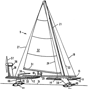
Figure 1 is an overall side view of a watercraft
three hull amphibious tube structure hydroplaning with ~ -
three supportiny hydroplaning hydrofoil~airfoil
structures with sail, engine, or electric motor
propulsion;
Figure 2 is a front view of the structure shown in
Figure 1 with engine or electric motor propulsion; ;
Figure 3 is a top vi~w of the structure shown in
Figure 1; ; .
Figure 9 is a fragmentary front view of Figure 2
showing a hydroplaning hydrofoil/airfoil structure and
the port bow hull;
WO9l/09767 ~ ~rl PCT/US9~/073
Figure 5 is a fragmentary side view of the port bow
hull and the hydroplaning hydrofoil/airfoil structure
shown in Figures 2, 3 and 4 shown along line 5-5 of
Figure 3;
Figure 6 is a ~op view of the hydroplaning
hydrofoil/airfoil structure shown in Figures 4 and 5
removed from the port bow hull;
Figure 7 is a front ~iew of a hydroplaning :
hydrofoil/airfoil structure and a cross-sectiorlal front .
view of the stern hull shown along line 8-8 of Figure 3;
Figure 8 is a side view of a hydroplaning
hydrofoil/airfoil structure and a fragmentary side view ~.
of the stern hull of the structure shown in Figures 1-3
and 7;
Figure 9 is a top vi.ew of the stern hydroplaning
hydrofoil/airfoil structure shown in Figures 7 and 8 :.
removed from the stern hull;
Figures 10 through 20E show various hydroplaning ..
hydrofoil/airfoil structures within the scope of the
20 present invention in see through top views of the bottom ~.
plane or planar-bottom surfaces, front or back views,
and cross-sectional or side views, some showing the :
optional, removable step, rudder and fin, with the
arrows indicating a reversible direction of motion;
Figures 21 through 29 are see through top views of
the bottom plane or planar-bottom surfaces of the
hydroplaning hydrofoil/ai.rfoil structures within the
scope of the present invention showing the broadest,
pre~erred, and most preferred compass degree angle
ranges of various leading and trailing edges;
: Figure 30 is an overall top view of a watercraft
three hull amphibious tube structure, which is a
modification of the one shown in Figures 1, 2 and 3,
with plvotable wings and hydroplaning hydrofoil/airfoil .
WO91/09767 PCT/US90/073~5
207 1~27
structures and with sail, engine or electric motor
propulsion;
Figure 30A iS an arched crossbeam ~ube connecto.r;
Figures 31A-D are enlarged cross-sectional views of
four connector shapes, the one in Figure 31B shown in
cross-section along line 7-7 of Figure 30 showing the
starboard pivotable wing for creating a negative or
positive air lift;
Figure 32 is an overall top view of a watercraft
three hull amphibious tube structure, which is a
modification of those shown in Figures 1-3 and 30, with
three supporting hydroplaning hydrofoil/airfoll
structures with sail, engine or electric motor
propulsion;
Figure 33 is the same front view of the port bow
hull shown in Figure 4 with a removable strut mounted
wheel; ::
Figure 34 is a fragmentary side view of the : .
structure shown in Figure 33; : :
Figure 35 is the same cross-sectional front view of
the stern hull shown in Figure 7 except having a
remo~able strut mounted wheel;
Figure 36 is a fragmentary side view of the
structure shown in Figure 35;
Figure 37 is an enlarged side view identical in
foil shape to the hydroplaning hydrofoil/airfoil
structure shown in Figures 4-6, with fin and struts
removed, showing a scaled down engine or electric motor
air propeller drive from Figure 1 plus a topside air
rudder and elevator attachment;
Figure 38 is the same side view of a hydroplaning
hydrofoil/airfoil structure shown in Figure 37 ascending
as an airfoil structure or flying wing planing or flying
through air in sustained flight;
. ''
WO91/09767 ~I PCT~US~ 735
r?~
Figure 39 is a front view of a hydroplaning
hydrofoil/alrfoil structure ~h~wn in Figure 37
hydroplaning on a fluid surfAce of water;
Figure 40 is a top view of a hydroplaning
hydrofoil/airfoil structure shown in Figures 37, 38, and
39; and
Figure 91 is an enlarged side view of a
hydroplaning hydrofoil/airfoil structure, identical in
foil shape to said structures shown in Figures 4, 5, and
6, gliding or planing through air.
etailed Description o~5hç Inven~ion
Reference is made to Figures 1-9, which show a
preferred embodiment of a watercraft 9 constructed with
a three hull amphibious tube structure component and a
preferred hydroplaning hydrofoil/airfoil structure
component. A three hull amphibious tube structùre
comprises a port bow hull lQ, a starboard bow hull 11
an~ a stern hull 12 forming a triangular configuration
all rigidly connected. The bow hulls are rigidly
attached via bolts or screws 17 by crossbeam tube
connectors 1~ and 1~, and stern hull 1~ is rigidly
attached to bow hulls lQ and 11 by a fore and aft
extending starboard tube connector 1~ and a fore and aft
extending port tube connector 1~. Stern hull 1~ is
positioned aft at a distance along a longitudinal
centerline between port bow hull lQ and starboard bow
hull 11 so that the three hulls are approximately
equidistant; however, the stern hull 1~ may be extended
further aft or forward 50 as to form an isosceles
triangle three point hull structure.
The forward extending starboard and port tube
connectors 15 and 16 are attached directly to stern hull
1~ by bolts or screws 1~ and to crossbeam tube
connectors 1~ and 1~ by bolts or screws ~, and each are
WO9l/09767 P~T/U~90/07355
- 2~7~27
angled out from the stern hull 1~ at about 16 to khe
starboard and about 16 to the port but may extend
straight Eorward at 0~ or angle out to about ~5~
measured from the longitud.inal centerline of watercraft
~. Each fore and aft extending starboard and port tube
connector 1~ and 1~ extends forward to a point in Eront
of the most forward crossbeam tube connector 1~ to
provide a connection and support for two forestays 19
and 20 leading to and attached to the upper part of
sailing rig mast ~1. Shrouds ~2, 24, and ~3, ~ of the
sailing ri~ are connected to the starboard and port fore
and aft extending tube connectors 1~ and .1
respectively. They also lead to and are attached to the
upper part of mast ~1. Backstay 27 is attached to stern
hull 1~. and leads to and is attached to the upper part
of mast ~1. Mast 2L is attached to the three hull tube
connector structure by means of an optional mast step
tube ~ (or a brace) positioned along the longitudinal
fore and aft centerline of watercraft 3 and attached at
each end to the two crossbeam tube connectors 13 and 14.
A stern hull crossbeam tube or brace ~ (optional)
and a removably mounted traveler connector tube or
support ~2 are positioned in the fore section of stern
hull 1~ and are attached to the deck of stern hull 1
and to the two fore and aft extending tube connectors 1
and 1~ for extra support. Traveler connector tube or
support 29 controls mainsheet ~0 shown in Figure 1
attached to boom ~1. In Figure 3, traveler connector
tube or support ~ is bent or angled forward from a
transverse position on each side of watercraft ~
longitudinal centerline; however, it may be positioned
across in a straight transverse position or curved
forward to accommodate mainsheet ~Q, sail ~2 and boom ~1
as shown in Figures 30 and 32.
.
WO91/09767 ~ PCT~US90/0735~
A cockpit 33 and steerlng tiller ~ (showing
direction of motion) are also positioned on stern hull
' .
Figure~i 30 and 32 show additional three hull
amphibious tube structure components. Ihe sail riyging
to support the rnast, sall and boom can be attached
anywhere on all three hulls and on the traveler
connector tube or support, preferably as shown.
The idea of a watercraft having three hulls spread
far apart and connected only with tubes or connectors
offers extremely light weight and stability; ideally
matched for sailing on hydroplaning hydrofoil/airfoils.
Materials of construction for all structures provided in
this invention can be any materials; preferably they are
buoyant and strong and can range from light weight
materials and metals to high-tech composite materials
The connectors or tubes shown in all hull
connections are not limited to straight connectors or
tubes. For example, Figure 30A shows crossbeam tube
connector 1~ arched or angled up slightly to a high
point at the watercraft longitudinal centerline to give
better wave clearance, and for optional cable, rope, or
xod reinforcements. Secondary tubes, rods, and braces
can also be added for additional strength. The bolts
and screws used for connecting the three hulls and tube
connectors are two of several fastening options which
include fastpins, hose clamps, pipe clamps, cast or
molded fittings, tube or pipe welding~ and other
fastening means known to those ln the art.
As shown in Figures 1 and 3, an engine or electric
motor 36 drives propeller _i7 as an auxiliary propulsion
means for watercraft ~. In Figure 2, the engine or
electric motor driven propeller is the sole power means.
The engine or electric motor ~ is attached to stern
hull ~ by a stanchion support ~. It is readily
WO91~09767 2 ~ 7 1 ~ 2 7 PCT~usgo/o73~
`apparent that other propulsion or power means can be
used depending upon the type of watercraft or aquatic
structure, the size, ~nd the market. For example, the
propulsion or power means can be an engine driven air or
water propeller, an electric motor driven air or water
propeller, human-powered pedal-driven air or water
propeller, human-powered paddle wheels or rowing with
oars, an engine driven w~terjet or air jet dri~e, rubber
band driven air or water propeller, a wind driven
sailing rig, a wind driven wing sail, or a tow line
affixed to a watercraft or affixed directly to the
hydroplaning hydrofoil/airfoil structure.
As shown in Figures 1-9, three hydroplaning
hydrofoil/airfoil structures ~, 90 and ~1 are attached
to the underside of hulls lQ, 11 and 1~ respectively of
the three hull amphibious tube structure to provide
supporting means to move the structure over water or a
fluid (as shown) including ice level 4~ or snow. Each
hydroplaning hydrofoil/airfoil struc~ure is attached to
each hull so that the longitudinal centerlines 61 of
each hull are coplanar with the top foil and bottom
centerlines 75 and 1~ of each hydroplaning
hydrofoil/airfoil structure. In Figures 1 and 2, the
hydroplaning hydrofoil/airfoil structures are shown
supporting the three hull watercraft 9 above water or
fluid level ~1, hydroplaning at high speed with very
little wetted surface.
Details of a most preferred hydroplaning
hydrofoil/airfoil structure as attached to a watercraft
are shown in Figures 4-9, 27, 2B and 29. Various
designs of the hydroplaning hydrofoil/airfoil structure
in its broadest and preferred aspects, including reverse ~ ;
direction versat.ili~y, are shown in Figures 10-26.
As shown in Figures 4 and 5 ~along line 5-5 of
Figure 3~, accelerating hydroplaning hydrofoil/airfoil
:
WO91/09767 ~ ~ PCT/USgOtO735
struc~ure ~ is shown lifting port bo~ hull lQ from
static water or fluid level 4~i to initial water or fluid
level ~ at low speed. As speed increases throuyh -the
hydrofoil/airfoil support range ~ to water or fluid
level 4~ at medium speed, the left side and right side
foil top surfaces 47 and ~ (sho~n more clearly in
Figure ~) are lifted completely above the water or fluid
providing airfoil lift; and, amazingly as hydroplaning
starts, when the two left and right fore foil top
sections 49 and 50 surface above water or fluid level 46
at medium speed, drag is reduced as hydroplaning
continues from water or fluid level ~ at medium speed
to water or fluid level 51 at high speed as shown by
wetted planar-bottom surfaces in Figures 4-6. The
15 hydroplaning support range is shown by ~ in Figure 4.
The exact speed and the water or fluid levels shown will
vary according to the type of watercraft or aquatic
structure, its displacement in water or fluid, the
propulsion or power means selected, wind, water or fluid
~0 conditions, the buoyancy of the hydroplaning -
hydrofoil/airfoil structures, the angle of attack (or
angle of incidence), and the size of the lifting planar-
bottom surface areas of the hydroplaning
hydrofoil/airfoil structures.
Each hydroplaning hydrofoil/airfoil structure
and 40 is attached to hulls lQ and 11 respectively by
two pivotal struts ~ and ~, and ~ and ~
respectively. As shown more fully in Figure 5, each
strut has a pivot hole ~Z and two vertical elongated
adjusting slots ~ and ~ near the top of each strut for
attaching the strut to each side of the hull with bolts
or screws 6Q (removed in this Figure 5 for clarity).
This enables each hydroplaning hydrofoil/airfoil
structure ~ and 40 either to be removed or to be
reversed 180 and still run as a hydroplaning
.~.' '
WO 91/~g767 2 ~ ~ 1 2 7 PC~/US9~/07355
hydrofoil/airfoil structuxe. Any pivot or detachment
means can be used in place of bolts or screws 6~ through
the stru~s. For example, va~ious gear, pulley, rope,
and cable connections can extend strut pivotal control
back to cockpit ~ and operate by hand, winch, radio or
computer controlled servos or a joy stick as in an
airplane. Pivot hole 57, in associatiorl with slots 5
and 5~, will swing and ad~ust hydroplaning
hydrofoil/airfoil structures 39 and 4Q so as to adjust
and control the angle of attack from about 1 to 16 in
the direction of motion from a horizontal longitudinal
line up to the longitudinal bottom centerline 7~,
preferably about 2 to 15~, or at an average of about 7
on water or fluid as shown in Figure 5.
Fins ~ are removably or reversibly attached to the
underside of each hydroplaning hydrofoil/airfoil
structure ~ and 40 along the longitudinal bottom
centerline 7Ç or parallel to the longitudinal bottom
centerline ~not shown).
Figures 7 ~along line 8-8 of Figure 3) and 8 show
hydroplaning hydrofoil/airfoil structure ~1 attached to
stern hull 1~ showing means for rotating the structure
to give directional control to the watercraft ~ (shown
by arrows in Figures 3 and 9). Steering tiller ~ is
attached by means of a tiller shaft ~, which extends
through shaft hole ~ in stern hull 12, to strut bracket
Ç5. Strut bracket ~ is attached to struts ~ and ~ by
bolts or screws 60. As with struts ~56, each stern
hull strut 6~ and ~1 has a pivot hole 57 and two
adjusting slots ~ and 59. Steering tiller 34 rotates
the entire hydroplaning hydrofoil/airfoil structure ~1
and rudder 72 for directional control of the watercraft.
As shown in Figures 2, 6 and 9, each strut 53-56, ~
fiÇ and ~ is attached to the left side foil top surface :- :.
35 ~ or the right side foil top surface ~a of each ~
: .; . , . . ' ' :,: '
WO9l/09767 ~ PCT/US90/073
12
hydroplaning hydrofoil/airfoil structure ~9, ~Q and ~1
by bolts, screws or ~ivets 7Q through a strut flange 71.
Any attaehment means can be used in place of bolts,
screws or rivets 7Q. Reversible fins ~2 ~shown with a
dotted line in Flgure 6), and reversible rudder 1~ are
attached to the underside of the hydroplaning
hydrofoil/airfoil~structures by bolts or screws 7~ and
7~ respecti~ely.
To more fully understi~nd the water-or fluid levels,
speed references and the hydroplaning hydrofoil/airfoil
structures shown in Figures 4-9, each hydroplanlng
hydrofoil/airfoil structure has a left side foil top
surface 47 and a right side foil top surface 4
converging to form a full length fore and aft
longitudinal top foil centerline 75, and a bottom
centerline 76 formed by two converging full length ~oil
planar-bottom surfaces, a left side foil planar-bottom
surface 77 and a right side foil planar-bottom surface
78~ Foil planar-bottom surfaces 77 and 7~ ascend
transversely from the longitudinal bottom centerline 7
to form a dihedral angle of about 18 as shown or in the
range of about 2 to 50 broadly or preferably also in
the range of about 2u to 50 or most preferably in the
range of about 2 to 30. The 18 dihedral angle shown
is the angle of inclina~ion of the left and right foil
planar-bottom surfaces 77 and 1~ measured in compass
degrees up from a transverse horizontal line
intersecting the longitudinal bottom centerline 76.
Figure 13A shows a dihedral range of about 2 to 50.
As can be seen, having two converging foil planar-
bottom surfaces with ascending dihedral angles pxovides
a smoother ride in rough water than a flat bottom
surface, and substantially reduces the wetted surface
transversely when hydroplaning at water or fluid level
WO9l/09767 2 D ~1 ~ 2 P7CT/US90/073
13
46 at medium speed, and water or fluid level 51 at high
speed.
Each left side foil planar-bottom suirface 77 and
right side foil planar-bottom surface 1~ has a fore foil
planar-bottom section (7.9 and ~Q respectively) which is
a forward extension along the longitudinal bottom
centerline 76. Each fore foil planar-bottom section has
a swept-back leading edge of 60 as shown or one ranging
from about 0 transversely from the longitudinal bottom
centerline 76 to about 80 swept-back broadly or
preferably ranging from about 30 to about 75D swept-
back or most preferably ranging from about 45 to about
70 swept-back. As used herein, all forward swept ancl
swept-back leading and trailing edges are measured in
15 compass degrees transversely to the longitudinal bottom
centerline 1~ as shown with arrows and compass degrees
in Figures 14, 16, 18, 19, and 21 through 29.
The length of each fore foil planar-bottom section
7~ and ~Q, as shown in Figures 5 and 6, is about the
first one-third of the entire length or chord of the
hydroplaning hydrofoil/airfoil structure along
longitudinal top foil and bottom centerlines 75 and 76i
however, the length of the fore foil planar-bottom
sections in their broadest aspects can range from 0
shown in Figure 23 or in the preferred length of about
one fourth of the choxd length shown in Figure 26 to ~ ~.
about the first two-thirds to three-fourths of the chord ::~:
length along top foil and bottom centerlines 75 and 76
shown in Figures ~2 and 25.
Each left side foil planar-bottom surface 77 and --
right side foil planar-bottom surface 7~ has an aft foil :-:
planar-bottom section which is a backward or aft
extension along the longitudinal bottom centerline 76.
As shown in Figures 4 6, each aft foil planar-bottom .:
sec-ion 68 and ~ at high speed water or fluid level ~
..~'~. .
''"
. ~
W09l/09767 ~ PCT/~S90/073
1~
has a forward swept trailing edge ~2 of 30 ~r one
ranging broadly from about 0-transversely from
longitudinal bottom centerline 7~ to about 75 forward
swept or preferably ranging from about 5 to about 60
forward swept or most preferably from about 10 to about
45 forward swept. The trailing edge ranges are
described more fully in Figures 21-29.
The length of each aft foil planar-bottom section
~ and 69 is about the last one-fourth to about one-
third of the entire chord length of the hydroplaninghydrofoil/airfoil structure along longitudinal bottom
centerline 76 at high speed water or fluid level ~1 as
shown in Figures 5 and 6. The aft foil planar-bottom
sections ~ and ~ vary in ~etted surface area and
length with speed and load; however, it is the section
of the hydroplaning hydrofoil/airfoil structure which
provides for high speed hydroplaning.
The left side and right side foil planar-bottom
surfaces 77 and 7~ have left wing and right wing forward
swept leading edges ~1 of 12 as shown in Figures 1
through 9; however~ left and right leading edges ~1 can
be forward swept in the broad range of about 0
transversely from longitudinal bottom centerline 76 to
about 75 forward sweep, or preferably in the range of
about 2 to about 60 forward sweep, or most preferably
in the range of about 4 to about 45 forward sweep.
Foil planar bottom surfaces 77 and 78 have forward swept
trailing edges coextensive with aft -foil planar-bottom
section trailing edge ~, i.e., forward swept 30 as
shown in Figures 1 through 9, but with forward swept
ranges as described above and in Figures 21 through 29.
Relative to performance advantages, it should be
added that incorporating hydroplaning hydro~foil/airfoil
forward swept left wing and right wing planar-bottom -
surfaces with transverse ascending dihedral angles and a
- . . . , . , ~ ... : . . .. ,: ~ . ... . ~.. . . .. . .
WO91~09767 P~T/VS9~/073~5
-- 2~71~27-
positive anqle of attack in the direction of motion with
leading edges and trailing ~dges that sweep forward, is
not just an ~ye-catching idea to be different, b~lt it is
very functional in that the forward swept leading edges
actually lift above the water or fluid surface providing
airfoil lift through air and to facilitate hydroplaning
of the fore foil and aft foil planar-bottom sections to
achieve wave clearance sooner during acceleration at
medium speed, as compared to swept-b~ck leading edges
that do not lift above the water or fluicl as soon during
acceleration, or lift a~ove waves with as much
clearance. The end result is achieved when the forward
swept aft foil planar-bottom sections 6~ and 69
hydroplane at high speed water or fluid level 51. This
enables a watercraft or aquatic structure to perform at
high speeds, touching the water or fluid surface with
extremely little drag and wetted bottom surface with
both hydroplane and airfoil lift, ideal for smooth water
and skip planing over wave crests and through air.
Figures 10 through 20E will describe various
configurations of the hydroplaning hydrofoil/airfoil
structures of this invention in see through foil top
views of the bottom plane or planar-bottom surfaces,
cross-sectional ~iews, and front or back views. Where
possible, the reference numerals used in Figures 1-9
will be used for consistency and ease of understanding.
Figures 6, 10, 11, 12, 13 and 18 structures are for
planing on a fluid surface of ~ater and for planing or
flying through a fluid preferably air. Figures 14, 16
and 19 structures are for planing on a fluid surface of
~ater.
Figure 10 shows a see through top view of the ..
bottom plane or planar-bottom surfaces of a hydroplaning
hydrofoil/airfoil structure having longitudinal bottom
center1ine l~ formed by two converging full length left
' ,
. .
"-
WO91/097fi~
PC~/US~/073
16
side and right side foil planar-bottom surfaces 77 and
7~ ascending transversely up from a horizontal line at
about 2 to 50 predetermined dihedral angle (shown in
Figure 13A) to the lef~ and right sides of the
longitudinal bottom centerline 76, foil planar-bottom
surfaces 77 and 1~ having fore foil planar-bottom
sections 79 and ~Q respectively, swept-back with 60~
leading edges. Foil planar-bottom surfaces 77 and 78
have transverse or about 0 leading edges 81 and 30
forward s~ept trailing edges ~ converging on the
longitudinal bott~m centerline 76 aft, forming aft foil
planar-bottom sections 6~ and 69.
Amphibious, and reverse direction performances are
described with reference to the structure of Figure 10,
however these performances apply equally to the
structures of the other drawings having a reversible
arrow. Optional holes a~ along longitudinal bottom
centerline ~ provide a means to bolt or screw a fin, or
rudder to the underside of the structure along the
longitudinal bottom centerline 1~ as in Figure 17 or
parallel to the longitudinal bottom centerline such as
along lines ~ and 86 in Figure 13. Optional holes ~
along the bottom centerline ?~ forming fore foil planar
bottom sections 79 and 80 also provide means to
permanently or reversibly affix a step to the underside
of the structure relative to the direction of motion of
the structure. Such a step, described in more details
in Figures l~A, 15, 16B, and 17, may be used for
improved hydroplaning over rough water or fluid and
running through snow. A detachable fin provides
improved lateral plane through water or fluid and snow,
and as a runner on ice as shown in Figures 4 and 5 by
ice level ~2- A detachable rudder provides improved
steering control through water or fluid and snow, and as
a steering runner on ice. It should be added that the
WO91/097fi7 2 ~ 7 ~ ~ 2 7 PCT/U~90/07355
17
step, fin or rudder may be removed in sorne water or
fluid conditions, but fin and rudder control would be
required in snow and as a runner on ice. The step/ fin
or rudder may also be made as permanent fixtures as
described in Figure 17.
By turning the hydroplaning hydrofo:il/airfoil
structure around fore and aft 180 and reversing the
step/ fin and rudder, the structure will operate in a
reverse direction of motion, and a watercraft or aquatic
structure will still perform as a hydroplaning
hydrofoil/airfoil structure within the scope of this
invention. Figures 17--17F show various forward motion
and reversible hydroplaning hydrofoil/airfoil cross
sections.
Figure 11 shows a see through top view of the
bottom plane or planar~bottom surfaces of a hydroplaning
hydrofoil/airfoil structure having longitudinal bottom
centerline 76 formed by two converging full length left
side and right side foil planar-bottom surfaces 77 and
7~ ascending transversely up from a horizontal line at
about 2 to 50 predetermined dihedral angle (shown in
Figure 13A) to the left and right sides of the
longitudinal bottom centerline l~, foil planar-bottom
surfaces 77 and ~ having fore foil planar-bottom
sections 1~ and ~Q respectively, swept-back with 60
leading edges. Foil planar-bottom surfaces 77 and 7
have 30 forward swep~ leading edges 81 and 45 forward
swept trailing edges ~ converging on the longitudinal
bottom centerline ?6 aft, forming aft ~oil planar-bottom
sections ~ and 69.
The optional holes ~9 along the longitudinal bottom
centerline 7~ provide the same amphibious and reverse
direction performances described in Figure 10.
Figure 12 shows a seé ~hrough top view of the
bottom plane or planar-bottom surfaces of a hydroplaning
WO ~ltO9767 ~ PCT/US90/07355
18
hydrofoil/airfoil structure having longitudinal bottom
centerline 7~ formed by two converging full length left
side and right side foil planar-bottom surfaces 77 and
7~ ascending transversely up from a horizontal line at
about 2 to 50 predetermined dihedral angle (sho~ln in
Figure 13A) to the left and~right sides of the
longitudinal bottom centerline 76, foil planar-bottom
surfaces 77 and 7~ having fore foil planar-bottom
sections 1~ and 80 respectively, swept-back with 60
leading edges. Foil planar-bottom surfaces 77 and 78
have 30 forward swept leading edges ~1 and 45 and 60
forward swept angular trailing edges ~ converging on
the longitudinal bottom centerline 76 aft; forming aft
foil planar-bottorn sections ~ and 6~.
The optional holes ~ along the longitudinal bottom
centerline 1~ provide the same amphibious and reverse
direction performances described in Figure 10.
Figures 13 and 13A show a see through top view of
four bottom planes or planar-bottom surfaces and a back
view of a hydroplaning hydrofoil/airfoil structure
having an elevated longitudinal bottom centerline 7~
formed by two full length intersecting left and right
foil planar-bottom surfaces 83 and ~ descending
transversely down from a horizontal line at about 30
predetermined negative dihedral angle to a lower left
longitudinal bottom line intersection 85 and a lower
right longitudinal bottom line intersection 8~ which
intersect with an outer left full length foil planar-
bottom surface 77 and an outer right full length foil
planar-bottom surface 78 respectively, each ascending
transversely up from a horizontal line at about 30
predetermined dihedral angle to the full hydroplaning
hydrofoil/airfoil wingspan with longitudinal cut off
ends. The dihedral angle broadest and preferred range
is about 2 to 50 as shown in Figure 13A and is the
WO9~/097Ç7 PCT/US90/073~ ~
2 7
19
broad and preferred range for all hydroplaning
hydrofoil/alrfoil planar-bottom surfaces shown in this
invention. The most preferred range is descri.bed in
Figures 27-29. This structure of Figure 13 has four
fore foil planar-bottom sections 7~, 80, S7 and ~S with
four swept-back leading edges of about 60. Fore foil
planar-bottom sections 7~ and ~ are formed by outer
left and right planar-bottom surfaces l~. and 78 and fore
foil planar-bottom sections a7 and ~ are formed by left
and right foil planar-bottom surfaces ~ and ~.
Planar-bottom surfaces ~ and ~ intersect outer left
and right planar-bottom surfaces 77 and 78 at lower left
and right longitudinal bottom line intersecti.ons ~S and ~
86 respectively, and with each other at elevated :
15 longitudinal bottom centerline 76. Outer left and right .
planar-bottom surfaces 77 and 78 have about 30 forward
swept leading edges ~1 and about 45 forward swept
trailing edges ~ converging on elevated longitudinal
bottom centerline 76 aft, forming four aft foil planar-
bottom sections ~ and ~. The compass degrèe
references of the leading and trailing edges in Figure
13 may vary within the preferred range described in .
Figures 4-9 and 24-26.
The optional holes ~ along the elevated
longitudinal bottom centerline 76 and lower left and
lower right longitudinal bottom line intersections ~
and 86 provide the same amphibious and reverse direction
performances as described in Figure 10. .
Figures 14 and 14A show a see through top view of ~ :
the bottom plane or planar-bottom sur~aces and a front
view of a hydroplaning hydrofoil/airfoil structure for
planing on a fluid surface of water having longitudinal
bottom centerline 76 formed by two converging full .
length left side and right side foil planar-bottom
surfaces ~0 and ~1 ascending transversely up from a
.
wO9l/Og7~7 ~ C~/~S90/0735
horizontal line at about 15 (sho~n in Fig. 14A)
predetermined dihedral angle to the left and right sides
of the longitudinal bottom centerline ~, foil planar-
bottom surfaces ~0 and ~1 having fore foil planar-bottom
S sections ~2 and ~ respectively, swept-back wlth about
45 leading edges ~ that extend to the full width foil
left and right planar-bottom surfaces ~0 and ~1,
concluding at outer ends 99 from which about 95 forward
swept t.railing edges 94 converge on the .longitudinal
bottom centerline 76 aft, forming aft foil planar-bottom
sections lQ~ and lQ~- The compass degree references of
the leading and trailing edges in Figure 14 may vary
with up to about 25 more or less sweep within the scope
of this configuration. Leading edges ~ and trailing
edges 94 may be optionally curved or angled inward or
outward as shown in Figure 14 and Figures 18 and 12.
The dihedral angle range for foil planar-bottom surfaces
~Q and ~1 is described in Figure 13A. The stru~ture in
this Figure 14 and all other hydroplaning
hydrofoil/airfoil structure figures may be constructed
and operated in two halves separated along section line
6-6 vertical to longitudinal bottom line 76 forming two
structures.
A 25 dihedral angle hydroplaning step 95 is
attached with bolt or screw ~6 through hole ~ under
fore foil planar-bottom sections ~ and ~. A fin or
rudder ~1 is attached with bolts or screws ~6 on the
underside of the hydroplaning hydrofoil/airfoil
structure along longitudinal bottom centerline 76 or
~0 parallel to longitudinal bottom centerline 76. Step 95
and fin or rudder ~7 may be attached as a step and fin
combination, a step and rudder combination, fin only, or
rudder only; an~ bç permanently or reversibly attached
to the hydroplaning hydrofoil/airfoil structure having
the same amphibious and reverse direction performances
,~', , .
,
.
W0~1~09767 ~ ~ 7 1 5 2 7 PCT'US90/'~735~
21
as described in Figure 10. Step 9~ shown in Figuxe 14A
has a dihedral angle in the range of about 4 to 52~ up
from a horizontal transverse line and is the range for
all steps attached to any of the hydroplaning
hydrofoil/airfoil structures in this invention. Step
also has a wedge angle of attack of about 2 to 45 down
from longitudinal bottom centerline 76 and is shown in
more detail in Figures 15, 16B, and 17.
Figure 15 is a cross section view of Figures 14 and
16 along line 6-6 and longitudinal bottom centerline 76
showing a hydroplaning hydrofoil/airfoil cross section
from Figure 17 with step ~S and fin or rudder ~1
removably attached with bolts 96 (or screws or any other
means) to provide the same amphibious and reverse
lS direction performances as described in Figures lOt 14,
and l~A. The step 95 wedge angle of attack is in the ..
range of about 2 to 45 down from the longitudinal
bottom centerline 7~ as shown in Figure 15 or any other
figure where attached.
~0 Figures 16 and 16A show a see through top view of
the bottom plane or planar-bottom surfaces and a front
view of a hydroplaning hydrofoil/airfoil structure for
planing on a fluid surface of water having longitudinal
bottom centerline 7.~ formed by two converging full
length left side and right side foil planar-bo~tom
surfaces ~Q and ~1 ascending transversely up from a
horizontal line at about 15 (shown in Figure 16A) ..
predetermined dihedral angle to the left and right sides
of the longitudinal bottom centerline ~, foil planar-
30 bottom surfaces 90 and ~1, having fore foil planar~ : .
bottom sections ~2 and ~ respec~ively, swept-back with
about 60 leading edges ~ that extend to the full width : :~
foil left and right planax-bottom surfaces ~Q and 91, ~ :
concluding at longitudinal outer ends ~ from which
about 0 transverse trailing edges lQQ converge on the
. . '
WO91/09767 ~' P~T/US~0/0735~
,j`!--~
22
longitudinal bottom centerline 1~ aft, forming aft foil
planar-bottom sections lQ2 and 10~. The dihedral angle
range ~or foil planar-hottom surfaces ~Q and 91 is
descrlbed in Figure 13A. The compass degree references
of the leading and trailing edges in Figure 16 may vary
with up to about 25 more or less sweep within the scope
of this configuration. Leading edges ~ and trailing
edges lOQ may be optionally curved or angled inward o~
outward as shown in Figure 16 and Figures 18 and 12.
A 30 dihedral angle hydroplaning step ~5 is
attached with bolt or screw 96 through hole ~ under
fore foil planar-bottom sections ~2 and ~. A fin or
rudder 97 is attached with bolts or screws ~ on the
underside of the hydroplaning hydrofoil/airfoil
structure along longitudinal bottom centerline 76 or
parallel to longitudinal bottom centerline 7~. Step 95
and fin or rudder 97 may be attached in combinations as
described for Figures 14 and 14A; and may be reversibly
attached to the hydroplaning hydrofoil/airfoil structure
having the same amphibious and reverse direction
performances as described in Figure 10.
Figure 16B shows an isometric view of step ~
having a hole lQl which is in alignment with hole a g
under bolt or screw ~ in fore foil planar-bottom
sections 79 and ~Q or fore foil planar-bottom sections
and 93 through which bolt or screw ~ is used to
secure step ~ to the underside of the planar-bottom
fore sections. When used in the present invention, step
~ has an angle of attack in the range of about 2 to
45 down from longitudinal bottom centerline 7~ sbown in
Figure 15 and a dihedral angle in the range of about 4
to 52 up from a hori~ontal transverqe line shown in ~ :
Figure 14A. The step shQwn may be made permanent or
detachable and cut or shaped to fit along the underside
W O 9]~09767 PC~r/US90/073~5
207~327
23
of any of the hydroplaning hydrofoil/airfoil structures
of this invention.
Fi.gu.re 17 shows a longitudinal top foil centerline
~ and bottom centerline 76 cross section view of an
optionally re~ersible hydroplaning hydrofoil/airfoil
cross section that has identical foil shape from the
leading and trailing edges (~1 and 82) to the center of
the hydroplaning hydrofoil/airfoil chord length. This
figure shows a six percent center chord :maximum foil
thickness between curved top foil centerline 7~ and
straight bottom centerline 7~ as a percentage of its
chord length; however, the percent of foil thickness is
optional but usually around si~ percent of the chord
length or in a broad range of less than one percent as
in a sheet or plate to about twenty percent of the chord
length for extra buoyancy in wate.r and lift in water and .
air.
The cross sections in Figures 17-17F offer a :
substantial buoyancy range in water or fluid at static
or slow speeds to partially or totally support a light
weight watercraft, aquatic structure or a hydroplaning
hydrofoil/airfoil structure itself above or in water or . : :
fluid.
Figure 17 also shows a reversible rough water or ..
snow hydroplaning step ~ and a fin or rudder 97
attached with removable bolts ~ or screws through holes
to provide the same amphibious and reverse direction
performances as described in Figure 10. If only one
direction of motion is desired, the step 9~ and fin or
30 rudder ~7 may be made as permanent fixtures, by any ::
means, to the hydroplaning hydrofoil/airfoil structure
of this invention. It should be added that the step 95 : ;
and fin or rudder ~1 may be removed in some water or
fluid conditions, but fin or rudder control would be
required on snow and as a runner on ice. The fin or
WO91/0~767 ~ PCT/US9~/07355
.~ . ...
24
rudder 97 may also provide directional control through
air similar to fin ~ shown in Figure 41, and is an
option with all cross sections shown in Figures 17-17
Figure 17A shows a longitudinal centerline cross
section view of a hydroplaning hydrofoil/airfoil shape
designed to move primarily in one dir~ct:ion of motion
showing a step ~ and a fin or rudder 97 bolted or screw
attached ~ to the hydroplaning hydrofoil/airfoil
structure of this invention. The step, fin or rudder
may be made as permanent fixtures or completely removed
in some water or fluid conditions as stated in Figure
17. The step, fin or rudder may be attached by any
means.
The ten percent, forward of center chord, maximum
foil thickness in this Figure between the curved top
foil centerline 1~ and the nearly straight bottom
centerline 7~ is optional; but a broad range of less
than one percent as in a sheet or plate to twenty
percent of the chord length offers substantial buoyancy
in water or fluid at static or slow speeds to partially
or totally support a light weight watercraft, aquatic
structure or a hydroplaning hydrofoil/airfoil structure
above or in water or fluid.
Figure 17B shows a longitudinal centerline c.ross
~S section view of a hydroplaning hydrofoil/alr~oil shape
designed to move primarily in one direction of motion
showing an elongated teardrop cross section having ten
percent, forward of center chord, maximum foil thickness
between the curved top foil centerline 75 and curved
bottom centerline ~. The optional holes ~9 provide a
means to bolt or screw a detachable step, fin or rudder.
The foil thickness has a broad range of less than
one percent as in a sheet or plate to twenty percent of
the chord length in this figure, offering substantial
3S buoyancy in ~ater or fluid at sta~ic or slow speeds to
WV91/09767 ~ ~ 7 ~ PCT/~S90/0735
partially or totall.y support a light weight watercraft,
~quatic s~ructure or a hydroplaning hydrofoil/airfoil
structure above or in water or fluid.
Figure 17C shows a longitudinal centerline cross
section view of an optionally reversible hydroplaning
hydrofoil/airfoil shape showing thin, spaced,
substantially parallel top foil and bottom centerlines
7~ and 7~ that form a flat plate, planar, ox sheet
shaped hydroplaning hydrofoil/airfoil structure. The
small leading and trailing edges ~1 and ~2 offer less
resistance through water or a fluid including air and
over snow, and optional holes ~9 are for a detachable
step ~ or fin or rudder ~l- The foil thicknesis between
the top foil centerline 15 and bottom centerline 1~ may
be very thin or increased and curvature added to offer
substantial buoyancy in water or fluid at static or slow
speeds to partially or totally support a light weight : :.
watercraft, aquatic structure or a hydroplaning
hydrofoil/airfoil structure above or in water or fluid.
Figure 17D shows a longitudinal centerline cross
section view of a hydroplaning hydrofoil/airfoil shape :~
designed to move primarily in one direction of motion.
The leading edge in this figure is curved up severa.l
degrees ranging from about one degree to thirty-five ..
25 degrees to hydroplane over rough water or fluid or run :
over snow. The optional holes ~2 are for a detachable
step 95 or fin, or rudder 97. The foil thickness
between the top foil centerline 7~ a~d bottom centerline
1~ may be very thin as in a sheet or plate or increased ~;~
30 and curvature added to offer substantial buoyancy in :
water or fluid at static or slow speeds to partially or
totally support a light weight watercraft, aquatic
structure or a hydroplaning`hydrofoil/airfoil structure
above or in water or fluid.
~09l/09767 ~ P~T/U~90/07355
;
` 26
Figure 17E shows a longitudinal centerline cross
section view of an optionally reversible hydroplaning
hydrofoil/airfoil forming an elongated oval shape having
an airfoil cross section identical at the leading and
trailing edge3 81 and ~ to the center of the airfoil
chord length. As with the cross section shown in Figure
17, the percent of foil thickness between the curved top
foil centerline 75 and curved bottom centerline 76
ranges from less than one percent as in a sheet or plate
to twenty percent of the chord length. The foil
thickness may be increased and curvature added to offer
substantial buoyancy in water or fluid at static or slow
speeds to partially or totally support a light weight
watercraft, aquatic structure, or a hydroplaning
hydrofoil/airfoil structure above or in water or fluid.
Figure 17F shows a longitudinal centerline cross
section view of a hydroplaning hydrofoil/airfoil having
a substantially elongated wedge shape designed to move
primarily in one direction of motion. The foil
thickness or eIongated wedge angle between the top
centerline 7~ and bottom centerline 76 may be very thin
or increased and curvature added to offer substantial
buoyancy in water or fluid at static ox slow speeds to
partially or totally support a light wei~ht watercraft,
aquatic structurer or a hydroplaning hydrofoil/airfoil
structure above or in water or fluid.
Any of the hydroplaning hydrofoil/airfoil
structures of ~his invention can be made from metal;
composites, canvas sheets, paper sheets, plastic sheets,
fiberglass, caxbon graphite fiber, ~evlar~ (aramid
fibers), film sheets, fabric sheets, plastic or wood
struts, foam or balsa core materials, molded plastic,
laminated wood or plywood. Other wing covering
materials and structural materials may be used to
.
.
WO91/09767 2 0 7 1 ~ 2 7 ~CT/V~gO/07355
27
fabrica-te or mold the hydxoplaning hydrofoil/airfoil
structures of this invention.
Figure 18 provides a general descriptive reference
to all top views and see through foil top views of the
bottom plane or planar-bottom surfaces of the
hydroplaning hydrofoil/airfoil structure in this
invention showing the shape or dotted line edge
curvature options of all foil planar-bottom sections
including leading edges ~1 and ~ in Figures 12, 14, 16,
18, 19 and trailing edges ~, 94, and lQQ in Figures 12,
14, 16, 18 and l9, and the detachable hydroplaning 3tep
95 in forward and reverse positions with holes ~ along
the longitudinal bottom centerline 76 for attaching an
optionally reversible fin or rudder 97.
First, all forward swept and swept-back leading and
trailing edges, in all figures, are measured in compass
degrees transversely to the longitudinal bottom
centerline 76 as shown for clarity with arrows and
compass degrees in Figures 14, 16, 18, 19, and 21
through 29.
Second, all leading edges and trailing edges may be
straight line edges or optionally curved or angled
inward or outward to various curvatures, compound
curves, angles or degrees as shown in Figure 18 and
25 Figures 12, 14, 16, and 19 within performances and the
scope of this invention. All edge intersections may be
curved, rounded or angled inwardly or outwardly, as also
shown in Figures 18 and 13, and are within the scope of
this invention.
Third, the detachable hydroplaning st~p ~ shown
with dotted lin~s attached under the fore foil planar-
bottom sections 79 and ~Q may be turned around 180, and
reattached in a reverse position under the aft foil
planar-bottom sections 68 and 69 for reverse direction
of motion as described in Figure 10. The optional holes
WO91/09767 ~ ~ P~T/US90/0735
28
89 along longitudinal bottom centerline 75 provide a
means to attach the step ~ or fin or rudder 97 also as
described.in Figure 10.
Figure 19 shows a see through top view of the
bottom plane or planar-bottom surfaces of a hydroplaning
hydrofoil/airfoil structure for planing on a fluid
sur~ace of water and is the same as the one shown in
Figure 16 except that it has about 30 inverted swept- -
back trailing edges lQQ converging on the longitudinal
bottom centerline 1~ aft forming two aft foil planar-
bottom sections lQ2 and 103. The compass degree
references of the leading and trailing edges in Figure
19 may vary with up to about 25 more or less sweep and
are within the scope of this configuration. Leading ..
edges ~ and trailing edges lQQ may be optionally curved
or angled inward or outward as shown in Figures 19, 18,
and 12.
Figure 20 is a front view of a hydroplaning
hydrofoil/airfoil structure having a fore and aft
longitudinal curved top foil centerline 7$ and a bottom
centerline 76 formed by two converging full length foil
planar-bottom surfaces 77 and 1~, and leading edges ~1
ascending transversely at about 30 predetermined
dihedral angle to the left and right sides of .
longitudinal bottom centerline 76; however, the dihedral
angle can range from about 2 to 50 up in its broadest
aspects from a horizontal line as shown in Figure 13A.
Attached to the structure along the underside of bottom
centerline 76 is a transverse 40 dihedral angle step 25
and a vertical fin or rudder 97 attached with bolts or
screws ~. The dihedral angle of the step can range
from about 4 to 52 up from a horizontal line as shown
in Figure 14A.
Amphibious and reverse direction performances are
as described in Figure 10.
. ' '
. :
WO9I/0976, PCT/US90/07355
2~7~27
29
Figure 20A is a front view of a hydroplaning
hydrofoil/airfoil structure having a fore and aft
longitudinal curved top foil centerline 1~ and a bottom
centerline 1~ formed by two converging full length foil
planar-bottom surfaces 11 and 78 and leading edges ~1
ascendin~ transversely up through a gradual downward
curve or arch between the longitudinal bottom centerline
1~ and two foil tips or wing tips as shown. A straight
line or chord drawn between the longitudinal bottom
centerline 1~ and either wing tip gives a dihedral angle
in a range of about 2 to 50.
As in other Figures, a vertical fin or rudder ~7 is
attached with bolts or screws ~6. Amphibious and
reverse direction performances are as described in
Figure 10.
Figure 20B is a front view of a hydroplaning
hydrofoil/airfoil structure having a fore and aft
longitudinal curved top foil centerline 75 and a bottom
centerline 76 formed by two converging full length foil
planar-bottom surfaces 77 and 1~ and leading edges ~1
ascending transversely in a gradual upward curve between
the longitudinal bottom centerline 76 and two foil tips
or wing tips as shown. A straight line or chord drawn
between the longitudinal bottom centerline 76 and either
wing tip gives a dihedral angle in a range of about 2
to 50. As in other Figures, a step, vertical fin or
rudder may be attached with bolts or screws through the
dotted longitudinal centerline hole 8~ ~or holes) shown
in this figure. Amphibious ~nd reverse direction
performances are as described in Figure 10.
Figure 20C is a front view of a hydroplaning
hydrofoil/air-foil structure having a fore and aft
longitudinal curved ~op foil centerline ~ and a bottom
centerline 76 formed by two converging full length foil
planar-bottom surfaces 77 and l~ and leading edges ~
' '
.
~::
W091/09767 ~ ~ PCT/~S90/07355
ascending transversely at high and low dihedral angles
between the longitudinal bottom centerline 76 and two
foil tips or wing tlps as shown. A straight line or
chord drawn between the longitudinal bottom centerline
1~ and either wing tip gives a dihedral angle in a range
of about 2 to 50. As in other Figures, a step, fin or
rudder may be attaehed with bolts or screws through the
dotted longitudinal centerline hole ~ (or holes) shown
in this figure. Amphibious and reverse direction
performances are as described in Figure 10.
Figure 20D is a front view of a hydroplaning
hydrofoil/airfoil structure having a fore and aft
longitudinal curved top foil centerline 75 and a bottom
centerline 76 formed by two converging full length Eoil
planar-bottom surfaces 77 and 1~ and leading edges ~1
ascending transversely at low and high dihedral angles
between the longitudinal bottom centerline 76 and the
two foil tips or wing tips as shown. A straight line or
chord drawn between the longitudinal bottom centerline
76 and either wing tip gives a dihedral angle in a range
of about 2 to 50. As in the other Figures, a step,
fin or rudder may be attached with bolts or screws
through the dotted longitudinal centerline hole ~ ~or
holes) shown in this figure. Amphibious and reverse
direction performances are as described in Figure 10.
Figure 20E is a front view of a hydroplaning
hydrofoil/airfoil structure having full length left side
and right side foil planar-bottom surfaces 77 and 78 and
leading edge ~1 ascending transversely as shown from a
center wing continuous curve to upward curved wing tips.
A straight line or chord drawn from center wing leading
edge 81 tv either wing tip gives a dihedral angle in the
range o about 2 to 50 up from a horizontal line. A
step, fin or rudder described in Figure 20D is optional.
W093/09767 PCT/US90/0735~
31 2~71~27
Amphibious and reverse direction performances are as
described .in Figure 10.
Figures 21, 2~ and 23 are see through foil top
views of the bottom pliine or planar-bottom surfaces of
hydroplaning hydrofoil/airfoil structures for planing on
a fluid surface of water showing leading and trailing
edges in their broadest aspects within the approximate
compass degree range and scope of this invention.
Figure ~2 structure will also plane through a fluid
preferably air as described hereinafter for Figure 22.
All forward swept and swept-back leading and trailing
edges in all Figures are measured in approximate compass ''
degrees transversely to the longitudinal bottom
centerline 1~ as shown with arrows in Figures 14, 16,
18, 19 and 21-29. As with earlier drawings, the
reference numerals are the same for clarity and
simplification.
Fisure 21 is a see through ~op view of the bottom
plane or planar-bottom surfaces which shows the leading
edges of the fore foil left and right planar-bottom
sections 7~ and 8Q swept bac,k at about 80. The leading
edges ~1 of the left and right side foil planar-bottom
surfaces 77 and 78 have a forward sweep of about 75.
Trailing edges 82 of the left and right aft foil planar-
bottom sections ~ and ~ are forward swept at about
75. An optional step and fin or rudder can be attached
to the underside of the structure along bottom
centerline 1~ with bolts or screws through holes ~2 as
described in Figures 10 and 17, and in other figures.
Figure 22, as with Figure 21, is a see through top
~iew of the bottom plane or planar-bottom surfaces which
shows the leading edges of the fore foil left and right
planar-bottom sections 79 and ~0 swept-back at about
80; however, as shown in this figure, leading edges ~1
of the left and right side foil planar-bottom surfaces
~ PC~US90/0735
77 and 1~ are perpendicular to longitudinal bottom
centerline 76 (i.e., about 0 transverse sweep).
Trailing edges ~ of the left and right aft foil planar-
bottom sections ~ and ~ are also perpendicular ~o
longitudinal bottom centerline 7~ ~i.e., about 0
trallsverse sweep). This structure planes on a fluid
surface of water and also planes through a fluid
preferably air as claimed. Again, an optional step and
fin or rudder can be attached to the underside of the
structure along bottom centerline 76 with bolts or
screws through holes ~ as described earlier in Figures
10, 17 and other figures.
Figure 23 is a see through top view of the bottorn
plane or planar-bottom surfaces which shows the leading
edges of the fore foil left and right planar-bottom
sections 79 and ~Q and the left and right side foil
planar-bottom surfaces 77 and 78 both at about 0
transverse ~weep (i.e., perpendicular to bottom
centerline 76). As in Figure 22, trailing edges ~ of
the left and right aft foil planar-bottom sections
~nd ~ are also at about 0 transverse sweep (i.e.,
perpendicular to bottom centerline 76). With this
configuration, an optional step ~ is attached to the
underside of left and right fore foil planar-bottom
sections 1~ and 80 with bolt or screw ~ to the
underside of the structure along longitudinal bottom
centerline 76. Step ~ has ascending left side and
right side dihedral angles in the range of about 4 to
S2 as shown in Figure 14A and left and right side foil
planar-bottom surfaces 77 and 7~ e~ch have an ascending
transverse dihedral angle from the bottom centerline 1
in the range of about 2 to 50 as shown in Figure 13A.
A fin or rudder ~7 is attached by bolts or screws 96 to
the underside of the hydroplaning hydrofoil/airfoil
35 structure along longitudinal bottom centerline 1~ to ;
W09]/09767 PCT/U~0/0735
2~7~ ~7
33
pr~vide di.rectional control at hydroplaning speeds
described in Figures 9, 5, 6, 7 and 8. The step, fin or
rudder can be made as permanent fixtures by any means.
The angle of attack for the broadest aspects of the
structure is about 1 to 16 up from a horizontal
longitudinal line to the longitudinal bottom centerline
7~ as shown in Figure 5.
Figures 24, 25 and 26 are see through foil top
views of the bottom plane or planar-bottom surfaces of
hydroplaning hydrofoil/airfoil structures for planing on
a fluid surface of water or through a fluid preferably
air showing leading and t.railing edges in their
preferred aspects within the approximate compass degree
range and scope of this invention. Again, the reference
numerals are the same for clarity and simplification.
Figure 2~ is a see through top view of the bottom
plane or planar-bottom surfaces which shows the leading
edges of the fore foil left and right planar-bottom
sections 7~ and 80 swept-back at about 75. Leading
edges ~1 of the left and right side foil plan~r-bottom
surfaces 77 and 7~ have a forward sweep of about 60;
and trailiny edges ~2 of the left and right aft foil
planar-bottom sections 68 and ~ are forward swept at
about 60. An optional step and fin or rudder can be
attached to the underside of the structure along bottom
centerline 76 with bolts or screws through holes ~ as
described in Figures 10, 17 and other figures.
Figure 25, as with Figure 24, is a see through top
view of the bottom plane or planar-bot~om surfaces which
shows the leading edges of the fore foil left and right
planar-bottom sections 7~ and ~0 swept-back at about
75; however, as shown in this figure, leading edges ~1
of left and right side foil planar~bottom surfaces 17
and 78 are forward swept at about 2. Trailing edges ~æ
of the left and xight aft foil planar-bottom sections
WO~1/09767 ~ P~T/U~gO/~7355
.
. - 3~
and ~9 are forward swept at about 5. Again, an
optional step and fin ox rudder can be atta~hed by bolts
or screws through holes 89 to the underside of the
structure along bottom centerline 76.
Figure 26 is a see through top view of the bottom
plane or planar-bottom surfaces which shows the leading
edges of the fore foil left and right planar-bottom
sections ~ and ~Q swept-back at about 30; and the
leading edges ~1 of the left and right side foil planar-
bottom surfaces 77 and 78 are forward swept at about 2.
Trailing edges ~2 of the left and right aft foil planar-
bottom sections 68 and 69 are forward swept at about 5.
An optional step can be attached to the underside
of left and right fore foil planar-bottom sections 79
and 80 by bolt or screw ~ as shown in ~igure 23 and is
made to conform to an ascending preferred transverse
dihedral angle of about 2 to 50 formed by the left and : .
right side foil planar-bottom surfaces 77 and 78.
Again, an optional fin or rudder can be attached by
20 bolts or screws through holes 89. The preferred angle ~ :
of attack for these preferred structures is about 2 to
15 up from a horizontal longitudinal line to the
longitudinal bottom centerline ~
Figures 27, 28 and 29 are see through foil top
views of the bottom plane or planar-bottom surfaces of
hydroplaning hydrofoil/airfoil structures for planing on . .
a fluid surface of water or through a fluid preferably
air showing leading and trailing edges in their most
preferred aspects within the approximate compass degree ~ :
30 range and scope of this invention. Reference numerals -~
are again the same for clarity and simplification. ~
Figure 27 is a see through top view of the bottom :
plane or planar-bottom surfaces which shows the leading ~ -
edges of the fore foil left and right planar-bottom
sections 79 and ~Q sw~pt-back at about 70. Leading
W~91/09767 PCT/~S90/0735~
2~7~527
edges 81 of the left and right side foil planar-bottom
surfaces 77 and 7~ have a forward sweep of about 95;
and trailing edges ~ of the left and right aft foil
planar-bottom sectlons ~ and 6~ are forward swept at
about 95. An optional step and fin or rudder czn be
attached to the underside of the structure along bottom
centerline 76 with bolts or screws through holes 89 as
described in Figures 10, 17 and other figures.
Figure 28, as with Figure 27, is a see through top
view of the bottom plane or planar-bottom surfaces which
shows the leading edges of the fore foil left and right
planar-bottom sections 7~ and 8Q swept-back at about
70; however, as shown in this figure, leading edges ~1
oE the left and right side foil planar-bottom surfaces
7Z and 7~ are forward swept at about 4. Trailing edges
of the left and right aft foil planar-bottom sections
68 and 6~ are forward swept at about 10~ Again, an
optional step and fiin or rudder can be attached by bolts
or screws through holes 89 to the underside of the ~:
structure along bottom centerline 76..
Figure 29 is a see through top view of the bottom ~.
plane or planar-bottom surfaces which shows the leading
edges of the fore foil left and right planar-bottom
sections 79 and 80 swept-back at about 45; and the
leading edges ~1 of the left and right side foil planar-
bottom surfaces 77 and 1~ are forward swept at about 4.
Trailing edges ~ of the left and right aft foil planar-
bottom sections ~ and ~9 are forward swept at about
10.
In the most preferred embodiments shown in Figures
27, 28 and 29, the ascending transverse dihedral angle
formed by the left and right side foil planar-bottom
surfaces 77 and 78 is most preferably in the ~ange of
about 2 to 30. The optional step when attached to the
underside of left and right fore foil planar-bottom
:
WO91/09767 ~ ~I PCr/VS90/07355
~ 36
`sections 1~ and 80 of these structures will conform to a
dihedral angle which is pred~termined. The angle of
attack for these most preferred structures is in the
range of about 2 to 15 up from a horizontal
longitudinal line to the longitudinal bottom centerline
76. An optional fin or rudder can be attached by bolts
or screws through holes 89 to the underside of the
structure along longitudinal bottom centerline 76.
Figure 30 is an o~erall top view of a sail ~2,
engine or electric motor ~6 and propeller ~1 power
option, removably attached to a three hull amphibious
tube structure component. Figure 30 has the same
hydroplaning hydrofoil/airfoil structure components ~
40 and ~1 as shown in Figures 1-9 and 32; however, the
three hull amphibious tube structure component shown ill
Figure 30 is a modification of the one shown in Figure :
3. In describing Figure 30, the same reference numerals
will be used as in Figures 1-9 for clarity and
simplification for the same parts. As shown, a three .i :
hull amphibious tube structure component consists of a
triangular three point hull float structure
interconnected with port and starboard pivotal wings lQ~5
and 106 and crossbeam tube connector 13 attached with .
bolts or screws 11 to the decks of a port bow hull lQ
25 and a starboard bow hull 11 having a removable mast ~1 `
stepped or attached to the center of crossbeam tube
connector 1~ on the longitudinal fore and aft centerline .
of watercraft ~
The stern hull 1~ is positioned aft at a distance : :
along a longitudinal centerline bet~een the port bow
hull lQ and starboard ~ow hull 11 so that the three
hulls are about equidistant; however, the stern hull 1~ .
may be extended further aft forming an isosceles
triangle three poin~ hull float structure or further
forward still forming a triangular three point huLl
: .. :...
' ` :~"'' '
WO91/0976/ PC~/US90/07355
2 Q 71 ~2 7
float structure. Attached to the stern hull deck with
bolts or screws 1~ is a fore and aft extending port tube
connector 1~, and a fore and at extending starboard
tube connector 1~, each angled out from the longitudinal
centerline of stern hull 12 at about 33~, but may range
from straight forward at 0 to an angle out of about 45
measured out frorn the longitudinal centerline of
watercraft 9. Each fore and aft extending starboard and
port tube connector 1~ and 1~ extends forward and out to
the starboard and port hulls 11 and 10, and optionally
bent, welded or braced forward to support each hull at
or near the longitudinal centerline ~1 of each hull for
a short distance along or near the centerline on the two
decks for screw or bolt attachments lQ~. The two fore
and aft extending tube connectors 1~ and 1~ may pass
o~er or under the crossbeam tube connector 1~, or even
bonded, braced or welded to the crossbeam tube to form
the same or similar structure as shown in this figure.
An optional stern hull crossbeam tube or brace ~, and
curved forward traveler connector tube or support ~,
are positioned across the fore section of stern hull 12
and are attached to the deck and two fore and aft
extending tube connectors 1~ and 1~ with bolts or screws
1~ or any other means for extra support, and controlling
the sail ~ and boom ~1 with mainsheet 30 (not shown,
see Figure 1). The traveier connector tube or support
may also be angled forward as shown in Figure 3 or
straight as sbown in Figure 32. A cockpit ~ and
steering tiller ~ (showing direction of motion) are
also positioned on the stern hull ~. The rigging
(forestays 19 and ~Q, backstay 27, and shrouds ~ and
~) to support the mast ~1, sail ~2 and boom ~1, may be
attached as shown or anywhere on the three hull
amphibious tube structure component.
WO9~/V9767 ~ P~T/US90/0735
: ~ 38
The port and starboard pivotal wings lQ~ and .lQfi,
also shown in cross section Figure 31B along line 7-7 of
Figure 30, may slide over, or fasten to crossbeam tube
connector 1~ with attachment means lQl to connect
control lines, rods, or cables lQ~ back to the stern
hull 1~ and cleated as shown~ Pivotal wings lQ~ and lQ~
are used for creating`a positive or negative air or
fluid lift to the watercraft; however, any other means
including winches, ]oy sticks, and radio control or
computer controlled ser~os can be used ~hich will
perform the same pivotal control function.
Details of connector shapes, in cross section, are
shown in Figures 31A, C and D. Figure 31A shows a
circular tube; Figure 31C, an elliptical connector for
reduced air drag; and Figure 31D shows a streamlined
airfoil or teardrop shaped connector. While the
connector cross sections shown are optional additions or
replacements to the crossbeam tube connector 1~, the ~ ;
shapes shown may vary in cross section and apply equally
to all tube connectors used, e.g., crossbeam tube
connectors 1~ and 1~, fore and aft starboard and port
tube connectors }~ and 1~, stern hull crossbeam tube or
brace 28 and traveler connector tube or support ~
As indicated in Figure 3, the idea of having three
hulls spread far apart connected only with tubes or
other streamlined connectors shown in Figure 31, offers
extremely light weight, and stability, ideally matched
for sailing on hydroplaning hydrofoil/airfoil
structures. Again, materials for construction may range
30 from light weight metal to high-tech composites for all ~ -
structures shown in this in~ention.
The tubes, or other streamlined connectors shown in
Figures 31A, C and D, are not limited to straight tubes
or connectors. For example, the crossbeam tube
connector 1~ and pivotal winss lQ~, 106 shown in Figure
'. '~'
W091/09767 PCT/US90/0735~
39 2~7~2~
`30 may be arched or angled up slightly to a high point
at the watercraft longitudinal centerline as shown in
Figure 30A to give better wave clearance, and for
optional cable, rope, or rod reinforcements. Secondary
tubes, rods, braces, and other connectors can be added
to the primary three hull amphibious tube structure
component and hydroplaning hydrofoil/air:Eoil structure
component within the design, function, and scope of this
invention.
Figure 32 is an over~ll top view of a sail ~,
engine or electric motor ~ and propeller 37 power
option, removably attached to a three hull amphibious
tube structure component. Figure 32 has the same
hydroplaning hydrofoil/airfoil structure components ~
~Q and 91 as shown in Figures l-9 and 30; however, the
three hull amphibious tube structure shown in Figure 32
is a modification of the ones shown in Figure 3 and
Figure 30. In describing Figure 32 (as in Figure 30),
the same reference numerals wil.l be used as in Figures
1-9 for clarity and simplification for the same parts.
As shown, a three hull amphibious tube structure
component consists of a triangular three point hull
float structure interconnected with two crossbeam tube
connectors l~ and l~ attached with bolts or screws ll to
the decks of a port bow hull lQ and a starboard bow hull
}1 havin~ a removable mast step tube or brace ~5,
positioned along a longitudinal fore and aft centerline
of watercraft g, attached at each end to the two
crossbeam tube connectors 1~ and l~.
The stern hull ~2 is positioned ~ft at a distance
along a longitudinal centerline between the port bow
hull LQ and starboard bow hull 11 so that the three
hulls are about equidistant; however, the stern hull l2
may be extended further aft forming an isosceles
triangle three point hull float structure or further
WO91/~9767 '1~ PCI/U590/~735~
, .
forward still forming a triangular three point hull
float structure. Attached to the stern hull deck with
bolts or screws 1~ is a fore and aft extending starboard
tube connector 1~, and a fore and aft extending port
tube connector 16, each angled out from the longitudinal
centerline of stern hull 12 at about 33~, but may range
from straight forward at 0 to an angle out of about 45
measured out fro~ the longitudinal centerline of
watercraft ~. Each fore and aft extending starboard and
port tube connector 1~ and 1~ extends forward ~nd out to
the starboard and port hulls 11 and lQ, diagonally
extending across the two decks or part way across for
screw or bolt attachments .~Q~. The two fore and aPt
extending tube connectors 1~ and 1~ may pass over, or
under the two crossbeam tube connectors 1~ and l~, or
even welded or braced to them to form the same or a
similar structure as shown in this figure. A stern hull
traveler connector tube or support ~ is positioned in ~ -
the fore section of the stern hull 1~ and is attached to
the deck and two fore and aft extending tube connectors
1~ and 1~ with bolts or screws 1~ for both extra support
and controlling the sail ~2 and boom ~1 with mainsheet
30 ~not shown, see Figure 1). The traveler connector
tube or support 29 may be positioned straight across as
shown or curved forward as shown in Figure 30 or angled
forward as shown in Figure 3. A cockpit ~ and steering
tiller 34 (showing direction of motion) are also
positioned on the stern hull 1~. The rigging ~forestays
1~ and 2Q, shrouds ~ and ~, and backstay 27) to
support the mast 2~, sail ~2, and boom ~1 may be
attached as shown or anywhere on the three hull
amphibious tube structure component.
As indicated in Figures 3 and 30, the three hulls
shown spread far apart connected only with tubes, or
other streamlined connectors shown in Figure 31 offer
W09l/09767 PCT/US90/07355
~Q71~27
41
extremely light weight and stability, ideally matched
for sailing on hydroplaning hydrofoil/airfoil
structures. Again, materials for construction may xange
from light weight metal to high-tech composites for all
structures in this invention.
The tube connectors in Figure 32 and other
streamlined connectors shown in Figure 31, are not
limited to straight tubes or connectors. For example,
the two crossbeam tube connectors 1~ and 1~ shown in
Figure 32 can be arched or angled up slightly to a high
point at watercraft 9 longitudinal centerline as shown
in Figure 30A to give better wave clearance, and for
optional cable, rope, or rod reinforcements. Secondary
tubes, rods, braces, and other connectors can be added
to the primary three hull amphibious tube structure
component and hydroplaning hydrofoil/airfoil structure
component within the design, function, and scope of this
invention.
The bolts o~ screws used for connecting the three
hulls and tube connectors together in any of the above
described figures offer two of several fastening options
which include fastpins, hose clamps, pipe clamps, cast
or molded fittings, tube or pipe bonding, bracing or
welding, and other fastening means within the design,
function, and scope of this invention.
Figures 33 and 34 are the same views as Figures 4
and 5; and Figures 35 and 36 are the same views as
Figures 7 and 8 except the hulls shown have strut
mounted wheels for operatlng the light weight three hull
amphibious tube structure component over land.
F~gure 33 is a front view of the port bow hull lQ;
and Figure 39 is a side view of the same structure shown
in Figure 33. The three hull amphibious tube structure
component of this invention, by inherent design, will
accommodate wheels 11~ and struts lQ~ attachments. To
W091~09767 ~ PCT~US90/07355
42
convert from a watercraft to wheels on land, the three
hydroplaning hydrofoil/airfoil s-tructures 3~, ~Q and ~1,
and struts ~ and ~7 as shown in :Figures 1-9 are
removed from the port ~nd starboard bow hulls lQ and L1,
and stern hull 1~. by removing bolts or screws ~0. The
three wheels 112 and struts lQ~ are then attached to the
three hulls using the same adjusting bolts or screws ~Q
in pivot hole ~1 and adjusting slots 5~ and 59, ready to
roll.
Shown in this view from top to bottom, is the
forward most crossbeam tube connector 1~, two bolts or
screw attachments 1~ through tube connector 1~ into the
port bow hull. lQ, two wheel struts 109 with bolt or
screw attachments 60, a wheel 11~, shaft llQ, and lock
nuts lll-
Figure 34 is a side view of Figure 33 with the samedescription, plus showing two crossbeam tube connectors
1~ and 1~, two vertical elongated adjusting slots S8 and ..
59, and a pivot hole ~l, with bolts or screws 60 removed
20 for clarity of view.
Figure 35 is the same cross section front vie~ of
the stern hull 12 shown in Figure 7, looking from the ~ .
front showing the stern hull 12, cockpit ~, fore and
aft starboard and port tube connectors 1~ and 1~, and
from top to bottom~ the steering tiller 34 with
direction of motion arrows, the tiller shaft 6~, shaft
hole ~, strut bracket ~, two adjusting bolts or screws
~Q, four remaining bolts or screws ~not shown), two
wheel struts lQ~ a wheel l12., shaft llQ, and lock nuts -.
llL. Th~ backstay 27, connected to the mast, is hidden
f~om view in back of the steering tiller. The engine or
electric motor ~6, propeller 37, and stanchion support
shown in Figure 1 are .removed in Figure 35 as a
matter of power option between sail ~ or engine ~ and
propeller ~l-
. .
. . ,:. ,
~: "
:
W~91/09767 2 ~ 7 1 ~ 2 7 PCT/~S9~/073~
43
Figure 36 is a side view of Figure 35 with the samedescription, plus showing two vertical elongated
adjusting slots ~ and ~, and a pivot hole ~l, with
bolts or screws ~Q removed for clarity of view. Bolts
or screws 1~ go through the fore and aft extending
starboard and port tube connectors 1~ and 1~ for
attachment to stern hull 1~-
The struts 109 and wheels 112 are all removable asshown in Figures 33-36. With wheels, struts, and
hydroplaning hydrofoil/airfoil structures removed, the
light weight three hull amphibious tube structure can
still be propelled on water, snow or ice with only a
rudder and flns or runners added under the hulls. In
addition, since the three hulls are not needed on land,
the strut mounted wheels 11~ and shafts llQ also may he
attached directly to the triangular light weight tube
structure in place of the three hulls.
As the hydroplaning hydrofoil/airfoil structure
component is adaptable by inherent design to support a
variety of light to medium displacement watercraft,
aquatic structures, and airfoil structures, the three
hull amphibious tube structure component, by inherent
design, accommodates most any power means and will
perform on water, snow, ice, and on land with wheel
attachments.
Application of the three hull amphibious tube
structure, as a matched component to the hydroplaning
hydrofoil/airfoil structure, provides watercraft size
options which range from toy size for kids, to model
size ~or radio control, and full size as a passenger
carrying aquatic structure or watercraft.
Power means may be attached to the three hull
amphibious tuhe structure as shown in Figure 1 or
directly to the hydroplaning hydrofoil/airfoil structure
35 as ahown in Figure 37 and range from a tow string or -~
WO~1/0~167 ~ pCT~US9~/~73~5
~ 44
line to toy size key wind up or rubber band power, to
model engine or electric motor power, to human power
rowing, human pedal-powered water or air propeller, to
outboard engines, inboard or inboard-outboard engines,
jet drives, airplane engine and propeller, wind powered
wing sails, wing masts, and wind sail power from model
size to passenger carrying and racing size.
Since the hydroplaning hydrofoil/airfoil structure
is designed to lift or plane itself, a watercraft, : .
aquatic structure or airfoil structure in or above water
or fly through air with fluid supported planes or planar
surfaces, said structure is adaptable by disclosed and
inherent design to lift or plane at various speeds a . ` .
variety of light to medium weight aquatic or airfoil
structures, to include kneeboards, water skis, a person
riding, standing or towed on said structure itself,
skiboards, sailboards, surfboards, aquatic structures
propelled by paddles or oars, aquatic structures
propelled by pedal-driven propeller or paddle wheels,
skiffs, canoes, shells, kayaks, dinghies, inflatable
watercraft, rowboats, hydroplane hulls, water scooters,
personal watercraft, pontoon or sponson float
structures, single or multihull sailboats and
motorboats, airboats, and ground-effect aircraft, :
seaplanes, ultrali~ht tube or strut frame airfoil wing
structures, airfoil wing wiatercraft, propelled airfoil
or planar flying wing aircraft, airfoil or planar wing
gliders, airfoil or planar wing kites, and other ~:
hydroplaning hydrofoil or airfoil fluid supported
structures.
The descriptions for the figures in this invention
provide details of design, construction, amphibious, and : ~
reverse direction versatility, power means, and aquatic ~ ~:
or air supported structures, buoyancy and one or more
fluid levels a hydroplaning hydrofoil/airfoil structure
WO91/09767 Pcr/usso/o73ss
~5 ~7~l~27
accelerates through to achieve either hydroplane or
airfoil support.
However, variations may be readily apparent to
those skilled in the art without detracting from the
realities of the structures and performances describ~d
in this inverltion. For example the hydroplaning
hydrofoil/airfoil structure in its pxeferred and most
preferred configurations offers additional performance
options that include planing on or through a fluid such
as water or air. Of course in an airfoil configuration
such as an ultralight wing aircraft, glider wing or
kite, the sa~e shape hydroplaning hydrofoil/airfoil
structure performs as an airfoil wing structure or
planar wing structure planing or flying through air
lS herein described.
As will be evidenced from the title of this
invention, a hydroplaning hydrofoil/airfoil structure
for planing on or flying through a fluid is shown
supporting itself in Figures 37 to 41. In describing
these Figures, the same reference numerals for the same
parts will be used as in Figures 9-6 for clarity and
simplification.
Figure 37 is an enlarged side view, similar to the
hydroplaning hydrofoil/airfoil structure 39 shown in
Figures 4, 5, and 6 with fin ~ and struts ~
removed, showing an engine or electric motor ~ and air
propeller 37 from Figure l mounted on stanchion ~ plus
a topside air rudder 11~ mounted along longitudinal top
foil centerline 1~ as shown in Figure 90 and elevator or
aileron ll~ attachment to air rudder ~ This buoyant
hydroplaning hydrofoil/airfoil structure ~ is shown
hydroplaning at water level ~1 prior to flight and in
Figure 38 the hydroplaning hydrofoil/airfoil structure
3~ or flying wing, planes or flies through air in
sustained flight.
W09l/09767 g~3?1 PC~/US9~/073
-` ~ 96
Figure 39 is a front view and Figu:re 40 is a top
view of the hydroplaning hydrofoil/airfoil structure ~9
shown in Figures 37 and 38 hydroplaning at water level
~1 and is similar to the structure shown in Figures 4-6
having the same reference numerals as shown in Flgure 6
with fin ~2 and struts ~-54 removed.
Figure 41 is a side view of the identical
hydroplaning hydrofoll/air~oil structure ~ shown in
Figures 4-6 gliding or planing through air. In this
Figure, fin ~ is retained.
As described for Figures 4-6, the hydroplanîng
hydrofoil/airfoil structure ~ in Figures 39 and 90 has
a left side foil top surface 47 and a right side foil
top surface 48. each having a fore foil top section (9
and ~Q respectively) converging to form a full length
fore and aft longitudinal top foil centerline 7~5, and a
bottom centerline 7~ formed by two converging full
length foil planar-bottom surfaces, a left side foil
planar-bottom surface 77 ~nd a right side foil planar-
bottom surface 78. Foil planar-bottom surfaces 77 and
7~ ascend transversely from the longitudinal bottom
centerline 7~ to form a dihedral angle of about 18 as
shown or in the range of about 2 to 50 broadly or
preferably also in the range of about 2 to 50 or most
preferably in the range of about 2 to 30. Each left
side foil planar-bottom sur:Eace 77 and right side foil
planar bottom surface 7~ has a fore foil planar-bottom
section (79 and ~Q respectively) which is a forward
extension along the longitudinal bottom centerline 76.
Each fore foil planar-bottom section has a swept-back
leading edge of 60 as shown or one preferably ranging
from about 30 to about 80 swept-back as described for
Figures 22 and 26 or most preferably ranging from about
45 to about 70 swept-back as described for Figures 27-
29.
W~9l/09767 ` P~T/US~0/07355
47 2 0 71~ 2 7
The length of each Eore foil planar-bottom section
1~ and ~Q, as shown in Figure 40 is the same as
described for Figures 5 and 6, and is about the first
one-third of the entire length or chord of the
hydroplaning hydrofoil/airfoil structure along
longitudinal top foil and bottom centerlines 1~ and l~;
howe~er, the length of the fore foil planar-bottom
sections in their broadest aspects can range from 0
shown in Figure 23 or in the preferred length of about
one fourth of the chord l.ength show~ in Figure 26 to
about the first two-thirds to three-fourths of the chord
length along top foil and bottom centerlines ~ and 75
shown in Figures 22 and 25
Each left side foil planar-bottom surface 1~ and
right side foil. planar-bottom surface 1~ has an aft foil
planar-bottom section which is a backward or aft
extension along the longitudinal bottom centerline l~- .
As shown in Figures 39 and 40, each aft foil planar- ~.
bottom section 68 and ~ at high speed water or fluid
20 level ~1 has a forward swept trailing edge 82 of 30 as
shown or one preferably ranging from about 0 to about
60 forward swept as described for Figures 22 and 24-26
or most preferably from about lQ to about 95 forward . .
swept as described for Figures 27-29.
The length of each aft foil planar-bottom section
~a and ~ is about the last one-fourth to about one-
third of the entire chord length of the hydroplaning
hydrofoil/airfoil structure along longitudinal bottom
centerline 76 at high speed water or fluid level ~1 as
shown in Figure 39. The aft foil planar-bottom sections
and ~ vary in wetted surface ar~a and length with
speed and load; however, it is the section of the
hydroplaning hydrofoil/airfoil structure which provides
for high speed hydroplaning prior to sustained flight.
WO91/~9767 ~ ~ PC~/U590/073
98
The left side and right side foil planar-bottom
surfaces 77 and 7~ have left wing and right wing for~ard
swept leading edges ~1 of 12 as shown in Figure 90;
however, left and right leading edges ~ can be forward
swept pre:Eerably in the range of about 0 to about 60
forward sweep as described for Figures 22 and 2~-26, or
most preferably in the range of about 4 to about 45
forward sweep as described for Figures 27-29. Foil
planar-bottom surfaces 77 and 1~ have forward swept
trailing edges coextensive with i~ft foil planar-bottom
section trailing edge ~, i.e., forward swept 30 as
shown, but with forward swept ranges as described above. :
The angle of attack may range from about 1 to 16
as described earlier for Figures 21--23 while
accelerating through water level ~1 before becom~ng
airborne in sustained flight. Once airborne, the angle
of attack varies greatly depending on speed, payload,
and whether the airfoil structure 3~ is ascending or
descending. Motor 36, air propeller ~l, stanchion 3~,
topside air rudder 11~ and elevator 11~ are as described
in Figure 37.
Optional holes ~ shown in Figure 40 accommodate
optional step 95 as described more fully for the
description of Figure 10 and as shown in Figures 14A,
15, 16B and 17. These optional holes will also
accommodate removable or pexmanent fin 62 as shown in
Figures 5 and 91 or a rudder 72 as shown in Figures 7
and 8.
Optional power, wing stabili~ers including winglets
and canards, landing wheels, and passenger or payload
carrying enclosures may be built in or attached to
various scale hyd~oplaning hydrofoil or airfoil
structures ~or gliding or propelled flight. Xn
concluding the description of this invention, a light
weight hydroplaning hydrofoil/airfoil structure selected
WO91/09767 PCT/US90/07355
` 2~7~5~
from Figures 4, 5, 6, and 17, enlarged butiof identical
foil shape, and merely having a weight.added to the fore
foil sections, performed repetitiously with a
surprisingly long glide path, planing Ol. gliding through
air, supporting the inherent versatility of the
disclosed structures of this invention t:o plane on or
fly through a fluid preferably either water or air.
This fore foil stabili~ed hydroplaning hydrofoil/airfoil
structure in the spirit of flight is shown gliding in
Figure 91.
In the claims which follow, reference to certain
Figures of the drawings is for the purpose of ease of
understanding and not by way of limitation.
WO9l/097~7 PCr/US90/0~3~5
-.
50
~7 ~5~ Glossàry Reference For Clarity
Hydroplaning Hydrofoil/Airfoil.Structures
and Amphibious and Aquatic Craft
Reference
5 ~m~xaL~ ~L~ Ei~r~ :
3 :
4 .: .
~5
, .
5 Cross section along line 5 3
6-~-6
~ :
. 6-~-6 Cross section along line 6 14, 16
~-7
, ~ .
201. ~-7 Cross section along line 7 30 .
~-~3 :
. ..
~. ~-8 Cross section along line 8 3
: ~. :
9. watercraft 1,3,30,32
lQ. port bow hull 2-5,30,32,33,34 :
11. starboard bow hull 1-3,30,32
12. stern hull 1-3,7,8,30,32,35,36
301~. crossbeam tube connector 1-5,30-34
1~. crossbeam tube connector 1,3,5,32,34
1~. fore and aft extending starboard 1-3~7,8,30r32,35,36
tube connector
. fore and aft extending port tube 2,3,7,30,32,35
conneotor
11. bolts ox screws 2-5,30,32,33,34
1~. bolts or screws 1,3,7,8,30,32,35,36
12. forestay (starboard s~de) 1,3,30,32
', .
:
WO91/09767 PCT/US90/073~
5~7~27
~Q. forestay (port side) 3,30,32
.21. mast . 1,3,30,32
. shroud (starboard side) 1,3,30,32
~. shroud (port side) 3,30,32
5 ~. shroud (starboard side) 1,3
. shroud (port side) 3
. bolts or screws 3
27. backstay 1,3,8,30,32,36
28. stern hull crossbeam tube or brace 3,30
10 ~. traveler connector tube or support 1,2,3,30,32
~Q. mainsheet
~1. boom 1,3,30,32
1~. mainsail or sail 1,3,30,32
1~. cockpit 1,3,7,8,30,
32,35,36
. steering tiller and directional 1,2,3,7,8,
arrows 30,32,35,36
. mast step tube or brace 3,32
~. engine or electric motor 1,2,3,30,32,
37-40
~1. propeller 1,2,3,30,32
37-40 :
38. stanchion support 1,2,37-90 :
~9. hydroplaning hydrofoil/airfoil 2,3-6,30,
structure 32,37-41
~Q. hydroplaning hydrofoil/airfoil 1-3,3Q,32
structure
~1. hydroplaning hydrofoil/airfoil 1-3,7-9,30,32
structure
30 ~2- ice level 4,5
. static water or fluid level 4,5
44. initial water or fluid level at 4,5 :
low speed
4~. hydrofoil and airfoil isupport 4 ~ :
range
WO 91/0~767 ~ PCT/VS90/073~5
. - ` i 52
. water or fluid level at medium 4,5
speed
47. left side foil top surface 6,7,9~39,40
4~. right side foil top surface 6,7,9,39,40
49. left fore foil top section 6,39~ 40
5Q. right fore foil,top section 6~ 39~ 40
51. water or fluid level at high speed 1, 2~ 9-8~ 37-39
. hydroplaning support range 4
53. pivotal strut (port outside) 2~3~4~6
54. pivotal strut (port inside) 2-6
. ,pivotal strut (starboard inside) 2r 3
56. pivotal strut (starboard outside) 1~2,3
57. pivot hole (to pivot struts) 5/8~34l36
~. vertical elongated adjusting slot 5r 8~ 34r 36
5~. vertical elon~ated adjustlng slot 5,8r34r36
~Q. bolts or screws 2-4,6r7r33,35
~1. longitudinal centerline (hulls) 3r 30r 32
6~. fin 1,2,4-6,41
63. tiller shaft 7r 8~ 35r 36
20 ~. shaft hole 7~8r9
65. strut bracket 2r7~9~ ~5~ 36
66. strut (starboard side) lr7~9
67. strut (port side) 7,9
~. left aft foil planar-bottom 6,10-13,18,
section 21-29, 39r 40
fi~. right aft foil planar-bottom 6~ 10-13r 18~
section 21-29r 39~ 40
lQ. bolts, screws or rivets 6,9
71. strut flange 6,9
72. rudd~r 1,2,7-9
7~. bolts or screws (to attach fins) 6
1~. bolts or screws (to attach rudder) 9
7~. longitudinal top foil centerline 5r 618~ 91 ~ :
17,20r40
WO9l/09767 P~T/US90f~7355
53 2Q713~7
7~. longi~udinal bottom centerline 5,8;10 29,39
77. full length left side foil . 6,7,10-13,18
planar-bottom surface 20~21-29,39,40
1~. full length right side foil 6,7,10-13,18,
planar-bottom surface 20,21-29,39,40
79. left fore foil planar-bottom 6,10-13r18,
section 21-29,39,40
QQ. right fore foil planar-bottom 6,10-13,18
section 21-29,39,40
1081. leading edge 6,7,9,10-13,17,18,
20-29,39,40
. trailing edge 6,9,10-13,17,18,
21-29,39,40
83. left side foil planar-bottom 13
surface
. right side foil planar-bottom 13
surface
8~. lower left longitudinal bottom 13
line intersection
86. lower right longitudinal bottom 13
line intersection
87. fore foil planar bottom section 13
88. fore foil planar-bottom section 13
~. optional holes 10-13,17,18,
20-22,24 29,40
9Q. full length left side foil 14,16,19
planar-bottom surface
~1. full length right side foil 14,16,19
planar-bottom surf~ce
30~. left fore foil planar-bottom 14,16,19
section :
. right fore foil planar-bottom 14,16,19
section
94. forward swept trailing edge 14
wo9~ q~ ~ PCT/US90/073
. .; - 54
95. step 14A,15,16A-B,17,
17A,18,20,23
. bolts or screws (to attach step, 14,14A,15,16,16A,
fin or rudder) 17,17A,20,20A,23
~l fin or rudder . 14,14A,15,16,16A,
17,17A,20,20A,23
9~. leading edge 19,16~19
99. outer ends 19,16,19
lOQ. trailing edge 16,19 .
10 101. hole (in step) 16B
~lQ2. left aft foil planar-bottom 14,16,19
section
103. right aft foil planar-bottom 14,16,19
section
15 lQ~. screw or bolt attachment~s 30,32
lQ~. port pivotal wing 30
lQ~. starboard pivotal wing 30,31B
lQl. attachment means 30,31B
lQ~. control lines, rods, or cables 30,31B
20 109. strut (for wheels) 33~36
110. shaft (for a wheel) 33,35
~11. lock nut 33-36
112. wheel 33-36
11~. topside air rudder 37,38,90
25 11~. elevator or aileron 37-qO
.