Note: Descriptions are shown in the official language in which they were submitted.
2x71595
PATENT
390100-2565
METHOD AND APPARATUS FOR RECORDING COMPRESSED AUDIO DATA
ON A VZbEO RECORDING MEDIUM
BACKGROUND OF THE INVENTION
This invE:ntion relates to video signal recording and,
more part~.cu~.arly, to a method and apparatus for recording
compressed audio data along w.i.th the video data on a record
medium, such as a digital video tape.
Digital signal recording apparatus, such as digital
vide~~ tape recorders (DVTR) h<~ve been developed far broadcasting
purpnses because of the excel:Lenc quality in video pictures that
are :.-eproduced therefrom. Heretofore, the emphasis of such
d~.gi~~al video recording systems has been on enhancing the video
picture. Typically, analog vwdeo signals are digitized by
samp_Ling the analog signal and converting each sample to an 8-bit
digital signal. Max~.mum video ~,nfo.rmatian is retained by
recording the 8-bit video samples in uncompressed form.
ConsE:quently, a substantial amount of record medium is needed to
record video programs of even minimal broadcasting length, such
as thirty minute programs.
DVTR systems have been developed with two distinct
formats: the so--ea:Lled component type digital recorder, known as
the D-1 format, and the so--called composite type digztal
recorder, known as the D-2 format. G7hen recording digital v~.deo
signals on video tape using the D-1-format, an audio recording
sector is provided =~n the middle of a track and zs preceded and
-1-
2~1~:~~~~
PATENT
390100-2565
1 followed by video recording sectors. Up to four channels of
2 audio information may be recorded in the audio sector. By
3 providing the audio sector in the middle of the track, it is
4 expected that the usual scanning heads will exhibit stable track
following, or tracking control, by the time those heads reach the
6 middle of the track during normal as well as special effect
7 scanning speeds. It has been found that small scanning errors
8 that may be present when the video sectors are scanned may be
9 more easily corrected and are less perceptible to a human
observer than if those same small scanning errors are present
11 when audio information is scanned. By locating the audio
12 information in the middle of a track, such small scanning errors
13 that may be present when audio information is reproduced are
14 minimized.
When video and audio information are recorded in the
16 D-2 format, the audio information is recorded in audio sectors
17 that precede and follow the video sector. The video sector is,
18 of course, substantially larger than each of the audio sectors,
19 and two channels of audio information may be recorded in each
audio sector. Thus, a total of four channels of audio
21 information may be recorded in the D-2 format, with two channels
22 of audio information preceding the video sector and two channels
23 of audio information following the video sector. The track
24 length of the D-2 format is shorter than the track length. of the
D-1 format by approximately 13%. As a result of this shorter
-2-
2~~~~9~
PATENT
390100-2565
1 track length, tracking control errors are minimized over the
2 entire length of the track and, thus, the flanking audio sectors
3 are scanned quite stably even when different tape speeds are used
4 to effect different reproducing modes (e. g. normal, slow speed,
high speed and special effects modes).
6 The four-channel audio recording capability of the D-1
7 and D-2 formats facilitates the recording of audio information
8 with high quality. If audio information normally is recorded as
9 two-channel audio data (e. g. left and right audio channels), then
the same two-channel audio data may be recorded twice so as to be
11 recorded as four-channel audio data. Such redundant recording is
12 most helpful in overcoming or correcting errors that otherwise
13 would result from drop-out in one or the other pairs of audio
14 channels. Four-channel audio recording also facilitates a
technique known as "after-recording", in which audio information
16 that is produced at a later time (i.e. subsequent to the
17 recording of video information) may be recorded. For example,
18 when audio information is edited or when audio information is
19 translated into a different language, such edited or translated
audio data usually is provided at a time that is substantially
21 delayed from the time that the video information is recorded.
22 Nevertheless, this after-recorded audio data is recorded quite
23 easily in two of the four audio channels that are available for
24 recording.
-3-
20'~~.~~~
PATENT
390100-2565
1 As mentioned above, digital video recording for
2 broadcasting purposes is accomplished without compression of the
3 video or audio data. While this assures a high quality of video
4 information, the fact that the video data is uncompressed means
that a substantial amount of record medium must be used to
6 accommodate such uncompressed video data. Since video tapes must
7 be of finite length, the need for more record medium to record
8 uncompressed video data results in a shorter overall recording
9 time. This inefficient use of video tape is an acceptable trade-
off for broadcasting purposes but is not acceptable for consumer
11 use. A desirable objective of video tape recording is the
12 capability of recording a broadcasted program in the user's
13 absence. Since a consumer may use his video recorder to record
14 several programs, it is important that commercially available
"blank" magnetic tape (such as in cassette form) be of sufficient
16 length to record the many programs that the user otherwise may
17 miss. Hence, for consumer use, a desirable objective is to
18 record video and audio data on a single record medium over a long
19 period of time.
To accommodate long recording periods, digital video
21 recorders for consumer use have been developed to record a
22 channel of audio data at a sampling rate of 48 KHz, with each
23 audio sample being digitized as a 16-bit sample. Such consumer-
24 type digital video recorders typica-lly are capable of recording
only two audio channels; and, as a result, if errors are present
_4_
2~~~~~~
PATENT
390100-2565
1 in the recorded audio information, it is difficult to correct
2 such errors. Thus, it is difficult to obtain high quality audio
3 recording in such two-channel consumer-type video recorders.
4 Furthermore, the typical consumer-type two-channel audio
recording capability does not easily permit the after-recording
6 of audio information.
7 OBJECTS OF THE INVENTION
8 Therefore, it is an object of the present invention to
9 provide an improved video recorder that is particularly adapted
for consumer use and which permits high quality as well as after-
11 recording of audio information.
12 Another object of this invention is to provide a
13 digital video recorder that is particularly adapted to record
14 long periods of video programs while permitting audio information
to be recorded with high quality as well as at a time subsequent
16 to the recording of the video information.
17 A further object of this invention is to provide an
18 improved method and apparatus for recording video and audio data
19 onto video and audio signal recording areas of a track of a
record medium, which overcome the aforenoted drawbacks and
?1 disadvantages of the prior art, and which are particularly
?2 adapted for consumer use.
'-3 An additional object of this invention is to provide a
?4 technique for recording four channels of compressed audio data on
?5 the same record medium as are recorded video data, with the four
-5-
PATENT
390100-2565
1 channels being used either for recording audio information with
2 high quality or for permitting the after-recording of audio data.
3 Various other objects, advantages and features of the
4 present invention will become readily apparent from the ensuing
detailed description, and the novel features will be particularly
6 pointed out in the appended claims.
7 SUMMARY OF THE INVENTION
8 In accordance with this invention, a method and
9 apparatus for recording audio data together with video data onto
audio and video signal recording areas of a track of a record
11 medium are provided. Input audio data that is supplied at
12 substantially the same time as the video data is compressed and
13 recorded in a first audio sector. Depending upon whether a first
14 or a second audio signal recording mode is selected, either
compressed audio data that is derived from the input audio data
16 or independent compressed audio data is provided and recorded in
17 a second audio sector.
18 The audio and video signal recording areas may be
19 included in one of a plurality of recording segments in a track
or, alternatively, these recording areas may comprise the only
21 audio and video areas in the track.
22 As one aspect of this invention, the compressed audio
23 data which is derived from the input audio data is provided by
24 determining an error in the compressed input audio data, and then
compressing that error. As a feature of this aspect, the error
-6-
2~~~~~~
PATENT
390100-2565
1 in the compressed input audio data is determined by digitizing an
2 input analog audio signal, compressing that digitized audio data,
3 expanding the compressed, digitized audio data, converting the
4 expanded audio data to analog form, determining a difference
between the converted analog audio data and the input analog
6 audio data, and digitizing the determined difference.
7 As another embodiment for determining an error in the
8 compressed input audio data, said compressed input audio data is
9 expanded and a difference between that expanded audio data and
ZO the digitized input analog audio signal is determined.
11 As yet another aspect of this invention, compressed
12 audio data that is derived from the input audio data supplied at
13 substantially the same time as the video data is provided by
14 supplying the same compressed audio data for recording in both
the first and second audio sectors, thereby recording redundant,
16 compressed audio data in both audio sectors.
17 The present invention also is directed to a method and
18 apparatus for reproducing the audio data that is recorded in the
19 aforementioned manner in the audio sectors described above.
BRIEF DESCRIPTION OF THE DRAWINGS
21 The following detailed description, given by way of
22 example, and not intended to limit the present invention solely
23 thereto, will best be understood in conjunction with the
24 accompanying drawings in which: -
_7_
_ 2071595
PATENT
390100-2565
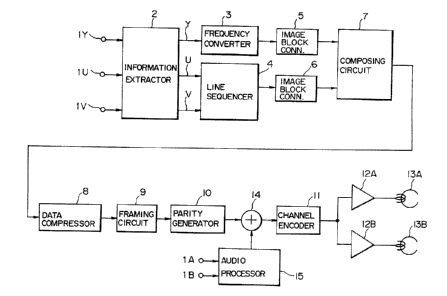
1 FIG. 1 is a block diagram of digital video recording
2 apparatus in which the present invention finds ready application;
3 FIG. 2 is a schematic representation of a segment (or
4 track) in which video and audio data are recorded;
FIG. 3 is a block diagram of one embodiment of
6 recording apparatus in accordance with the present invention:
7 FIG. 4 is a block diagram of digital video reproducing
8 apparatus for recovering digital audio and video information that
9 may be recorded by the apparatus shown in FIG. 1;
FIG. 5 is a block diagram of one embodiment of audio
11 reproducing apparatus that is compatible with the recording
12 apparatus shown in FIG. 3;
13 FIG. 6 is a block diagram of another embodiment of
14 audio recording apparatus which incorporates the present
invention;
16 FIG. 7 is a block diagram of audio reproducing
17 apparatus that is compatible with the embodiment shown in FIG. 6;
18 FIG. 8 is a block diagram of yet another embodiment of
19 audio recording apparatus which incorporates the present
invention;
21 FIG. 9 is a block diagram of audio reproducing
22 apparatus that is compatible with the embodiment shown in FIG. 8;
23 and
_g_
2~~~~~~
PATENT
390100-2565
1 FIG. 10 is a schematic representation of yet another
2 segment in which video and audio data are recorded in accordance
3 with the present invention.
4 DETAILED DESCRIPTION OF PREFERRED EMBODIMENTS
Referring now to the drawings, wherein like reference
6 numerals are used throughout, FIG. 1 is a block diagram of
7 digital video/audio recording apparatus in which the present
8 invention finds ready application. As an example, the video
9 recording apparatus shown in FIG. 1 may be used directly with a
video camera and may be incorporated in the same housing
11 therewith, such as a so-called "camcorder". Alternatively, the
12 apparatus of FIG. 1 may be supplied with video signals recovered
13 from broadcasted or previously recorded television signals. In
14 any event, the illustrated apparatus is comprised of an
information extractor 2, a frequency converter 3, a line
16 sequencer 4, image block converters 5 and 6, a data compressor 8,
17 a mixer 14, an audio processor 15 and recording heads 13a and
18 13b. Information extractor 2 is coupled to input terminals lY,
19 lU and 1V and is adapted to receive a digital luminance signal Y
and digital color difference signals U and V, respectively. In
21 one embodiment, the digital luminance and color difference
22 signals are derived from the three primary color signals red,
23 green and blue produced by a color video camera. Alternatively,
24 the digital luminance and color difference signals are derived
from reproduced television signals or from broadcasted television
_g_
20~1~~~
PATENT
390100-2565
1 signals. It will be appreciated that the derivation of digital
2 luminance and color difference signals Y, U and V and the
3 application of these signals to information extractor 2 are
4 conventional and further description thereof need not be
provided.
6 The information extractor functions to extract useful
7 luminance and color difference information from the digital
8 luminance and color difference signals supplied thereto and to
9 discard the usual video signals which do not comprise useful
video information. For example, signals that are included in
11 line intervals which typically are not displayed on a
12 conventional television monitor as well as various synchronizing
13 and equalizing signals are discarded. Information extractor 2
'14 includes output terminals to which the extracted digital
luminance signal Y and the extracted digital color difference
16 signals U and V are supplied, respectively.
17 Frequency converter 3 is coupled to information
18 extractor 2 and is adapted to convert the sampling frequency, or
19 data rate, of the digital luminance signal Y. The sampling
frequency of this luminance signal may be on the order of 13.5
21 MHz; and the frequency converter is adapted to reduce that
22 frequency to approximately three-fourths (3/4) of its original
23 sampling frequency. As will be known by those of ordinary skill
24 in the art, frequency converter 3 may be implemented by a thin-
out filter that prevents aliasing noise. The frequency-converted
-10-
'~Or~~.~~~
PATENT
390100-2565
1 digital luminance signal Y is supplied from frequency converter 3
2 to image block converter 5.
3 The output terminals of information extractor 2 to
4 which the extracted digital color difference signals U and V are
supplied are coupled to line sequences 4. The line sequences is
6 adapted to reduce the sampling frequency, or data rate, of each
7 of the digital color difference signals U and V to one-half (1/2)
8 of its original sampling frequency and to select alternate ones
9 of these frequency-reduced color difference signals on a line-by-
line basis. For example, one line of the frequency-reduced
11 digital color difference signal U is followed by the next line of
12 the frequency-reduced color difference signal V. Thus, line-
13 sequential, frequency-reduced digital color difference signals U
14 and V are produced by line sequences 4. These line sequential,
frequency-reduced color difference signals are supplied to image
16 ' block converter 6.
17 Image block converters 5 and 6 are adapted to form
18 blocks of frequency-reduced video signals supplied thereto from
19 frequency converter 3 and line sequences 4, respectively. For
example, a predetermined number of samples is arranged as an
21 image block by each of these image block converters. As
22 illustrated, image block converters 5 and 6 are coupled to a
23 composing circuit 7 which operates to form a single channel of
24 digital video data from the block o~ frequency-reduced digital
luminance signals and from the block of frequency-reduced, line
-11-
~0~1~9~
PATENT
390100-2565
1 sequential color difference signals produced by the respective
2 block converters. Composing circuit 7 is coupled to data
3 compressor 8 which is adapted to compress the data included in
4 the single channel of video information composed by the composing
circuit. For example, data compressor 8 may comprise an
6 orthogonal transform circuit, such as a discrete cosine transform
7 circuit, or it may comprise an adaptive dynamic range coder
8 (ADRC), or other known circuits. As a result, the amount of data
9 needed to represent the original luminance and color difference
signals is reduced,
11 The output of data compressor 8 is coupled to a framing
12 circuit 9 which operates to convert the clock frequency of the
13 data-compressed frequency-reduced luminance and color difference
14 signals to a clock rate that is particularly compatible for
recording. In addition, the framing circuit converts the block
16 structure format produced by image block converters 5 and 6,
17 composing circuit 7 and data compressor 8 to a frame structure
18 data format.
19 Framing circuit 9 is coupled to mixer 14 by way of a
parity generator 10. The parity generator operates in
21 conventional manner to generate parity bits from the frames of
22 compressed data supplied thereto by framing circuit 9, these
23 parity bits being used for error correction purposes during a
24 reproduction operation. Mixer 14 i-s supplied with compressed
audio signals from audio processor 15 in a manner to be described
-12-
~0~~~9~
PATENT
390100-2565
1 below. One embodiment of the audio processor is illustrated in
2 FIG. 3, and will be explained hereinafter. Suffice it to say
. 3 that audio processor 15 is supplied with audio signals, such as
4 analog audio signals, by way of input terminals lA and 1B. In
particular, the audio signals supplied to input terminal lA
6 preferably are comprised of two-channel audio signals (e. g.
7 stereo signals), and these audio signals are supplied to terminal
8 lA at substantially the same time as video data is supplied to
9 input terminals lY, lU and 1V. As will be described, audio
signals may be coupled to input terminals 1B to effect an after-
11 recording mode of operation.
12 Mixer 14 serves to combine the video data supplied
13 thereto from framing circuit 9 and parity generator 10 with audio
14 data supplied thereto by audio processor 15 and to couple the
combined, or mixed video and audio information to a channel
16 encoder 11. The channel encoder operates to reduce the low
17 frequency components of the video and audio data to be recorded
18 and may encode the video and audio data in conventional manner
19 and in accordance with typical recording codes, such as 1,7 code,
MFM code, NRZI, etc. The output of channel encoder 11 is coupled
21 to recording heads 13A and 13B by way of recording amplifiers 12A
22 and 12B, respectively.
23 The video recording apparatus illustrated in FIG. 1 may
24 be of conventional construction known to those of ordinary skill
in the art. Accordingly, in the interest of simplicity and
-13-
2~~~~~~
PATENT
390100-2565
1 brevity, further description of such recording apparatus is not
2 provided. The present invention is directed more particularly to
3 audio processor 15; and preferred embodiments of this audio
4 processor are described below in conjunction with, for example,
FIGS. 3, 6 and 8. However, for the purpose of the present
6 description, it should be appreciated that the mixed video and
7 audio data provided by mixer 14 are recorded in one or more
8 segments of a record track in accordance with the format
9 schematically illustrated in FIG. 2. In one embodiment, a
plurality of segments of the type shown in FIG. 2 are recorded in
11 a single track on the record medium, such as a single track of
12 video tape. In another embodiment, the segment shown in FIG. 2
13 comprises substantially the entire track.
14 As shown, a video signal recording area, identified as
"video sector", is followed by two successive audio signal
16 recording areas, identified as °'audio sector 1" and "audio sector
17 2'°. It will be recognized that the video and audio sectors shown
18 in FIG. 2 are not drawn to scale.
19 Preceding each sector is a preamble area and a margin
area, the preamble area having data and synchronizing information
21 recorded therein and the margin area being provided to permit
22 change-over in the reproducing apparatus as well as to
23 accommodate tolerances in the recording of video and audio
24 information. Each sector is followed by a postamble area; and it
is seen that adjacent sectors are separated by a region comprised
-14-
PATENT
390100-2565
1 of a postamble area, a margin area and a preamble area. The
2 signals recorded in the preamble and postamble areas preferably
3 are comprised of pulses having a repetitive frequency equal to
4 the clock frequency (or data bit frequency) of the respective
video and audio data recorded in the video and audio sectors.
6 Alternatively, the pulse signals may exhibit a frequency that is
7 a multiple or submultiple of such data bit frequency. The
8 purpose of these pulse signals is to enable a phase locked loop
9 (PLL) to lock onto the data bit frequency during a reproducing
mode such that the clock frequency of the reproducing apparatus
11 is synchronized to the clock frequency of the information being
12 reproduced from the record medium.
13 One embodiment of audio processor 15 which is
14 particularly adapted for recording four channels of audio
information now will be described in conjunction with the block
16 diagram shown in FIG. 3. This audio processor is adapted to
17 operate in one of two different audio signal recording modes: a
18 high quality mode, in which two-channel audio information is
19 recorded in four channels, or an after-recording mode, in which
two-channel audio information is recorded substantially
21 simultaneously with the video information, and different two-
22 channel audio information is recorded at a later time, subsequent
23 to the recording of the video information, thus constituting
24 "after-recorded" audio data. A se hctor switch 47 is used to
-15-
20~1~95
PATENT
390100-2565
1 select either the high quality or the after-recording mode, as
2 will be described.
3 Input analog audio signals are coupled to an input
4 terminal lA at substantially the same time as video data is
coupled to input terminals lY, 1U and 1V of the recording
6 apparatus shown in FIG. 1. Input terminal 1B of FIG. 3 is
7 adapted to receive analog audio signals at a later time, that is,
8 after the original video and audio data are recorded. Stated
9 otherwise, input terminal 1B is adapted to receive audio signals
far after recording.
11 Audio processor 15 is comprised of a high quality
12 processing section A which, in the embodiment shown in FIG, 3, is
13 comprised of an analog-to-digital (A/D) converter 34, a
14 compressor 35, an expander 37, a digital-to-analog (D/A)
converter 36, a difference circuit 61, an A/D converter 40 and a
16 compressor 41. The audio processor 15 also includes parity
17 circuits 38 and 44, ID/sync circuits 39 and 45 and a multiplexes
18 46. Input terminal 1A is coupled to A/D converter 34 which
19 functions to digitize the input analog audio signals supplied
thereto. In one example, this audio signal is a two-channel
21 audio signal. As mentioned above, the analog audio signal is
22 sampled at a sampling rate of 48 KHz. In the present invention,
23 each sample is represented by sixteen bits; and A/D converter 34
24 is adapted to operate at 1.536 MB/sec. to digitize two channels
-16-
~0'~~.~~~
PATENT
390100-2565
1 of audio signals supplied thereto by way of input terminal lA (48
2 KHz x 16 bits x 2 channels = 1.536 MB/sec.).
3 Compressor 35 is coupled to A/D converter 34 and is
4 adapted to reduce the frequency of the digitized audio signals by
half. Thus, compressor 35 operates as a band compression circuit
6 to convert the data rate of the digitized audio information from
7 1.536 MB/sec. to 768 KB/sec. The compressed audio data is fed
8 back to expander 37, to be described, and also is coupled to
9 parity circuit 38. The parity circuit functions in conventional
manner to generate parity bits and adds an error correction
11 parity code to the compressed digitized audio data supplied from
12 compressor 35. This audio data with an appended error correction
13 parity code is coupled to ID/sync circuit 39 which generates
14 identification data to identify the particular audio sector in
which this audio data is recorded and also generates
16 synchronizing data which is useful during a reproducing operation
17 to detect the audio data. For example, the sector ID and sync
18 data may be included in the preamble area that precedes audio
19 sector 1, shown in FIG. 2. In this example, it will be
appreciated that the sector ID data functions to identify the
21 audio sector as "sector 1".
22 As mentioned above, the compressed audio data produced
23 by compressor 35 is fed back to expander 37 which functions to
24 return the compressed audio data ta-its original data rate of
1.536 MB/sec. The output of expander 37 is coupled to D/A
-17-
~~'~:~ ~9
PATENT
390100-2565
1 converter 36 which re-converts the digitized audio data to analog
2 form. The reconverted analog audio signals are coupled to
3 difference circuit 61 whereat they are compared with the original
4 input analog audio signals supplied to terminal lA. Although not
shown, it will be appreciated that terminal lA may be coupled to
6 difference circuit 61 by way of a delay circuit which functions
7 to compensate for delays inherent in A/D converter 34, compressor
8 35, expander 37 and D/A converter 36. The difference circuit is
9 adapted to determine differences which may be expected between
the original input analog audio signal and the analog audio
11 signal that has been reconverted from its digitized and
12 compressed form. Such differences are referred to herein as an
13 error, and this error, which appears at the output of difference
14 circuit 61, is coupled to yet another compressor 41 by way of an
A/D converter 40. The combination of A/D converter 40 and
16 compressor 41 functions to digitize and compress the error that
17 may be present in the originally compressed audio data produced
18 by compressor 35. Stated otherwise, the compressed error
19 provided by compressor 41 comprises compressed audio data that is
derived from the original, compressed audio data produced by
21 compressor 35 and that had been supplied at substantially the
22 same time as the video data supplied to input terminals 1Y, lU
23 and 1V of the recording apparatus shown in FIG. 1.
24 The output of compressor 41 is coupled to a terminal a
of selector switch 47. As mentioned above, this selector switch
-18
20~~~9~
PATENT
390100-2565
1 operates to select a first or second audio signal recording mode,
2 these modes being described herein as the high quality and after
3 recording modes. When the high quality recording mode is
4 selected, switch 47 engages its terminal a, thereby coupling
compressor 41 to a parity circuit 44. This parity circuit is
6 substantially similar to aforedescribed parity circuit 38 and is
7 adapted to generate parity bits which may be added to the
8 compressed error signal produced by compressor 41 as an error
9 correction parity code. The compressed audio error data with
this added error correction parity code is coupled to ID/sync
11 circuit 45 which is similar to ID/sync circuit 39 and is adapted
12 to generate sector identification data which identifies audio
13 sector 2. In addition, a sync signal is generated by this
14 ID/sync circuit for use during a reproducing operation to detect
and recover the audio data recorded in audio sector 2. As will
16 also be described, ID/sync circuit 45 also generates mode
17 identifying data, such as high quality or after-recording ID
18 data.
19 Multiplexer 46 is coupled to ID/sync circuits 39 and 45
to select either the compressed audio data supplied from
21 compressor 35 (together with the error correction parity code and
22 ID and sync data added thereto) or the compressed error data
23 produced by compressor 41 (together with the error correction
24 parity code and ID and sync data added thereto) for recording
either in audio sector 1 or in audio sector 2 as heads 13A and
-19-
20~1~9~
PATENT
390100-2565
1 13B scan successive tracks across the record medium. As shown in
2 FIG. 3, the output of multiplexer 46 is coupled to mixer 14
3 whereat the compressed audio signals processed by audio processor
4 15 are combined with digital video signals, as produced by the
recording apparatus discussed above in conjunction with FIG. 1.
6 Selector switch 47 also may selectively engage its
7 terminal b to receive compressed audio data for recording in the
8 after-recording mode. As shown in FIG. 3, terminal 1B, which is
9 adapted to receive such after-recording audio signals, is coupled
to A/D converter 42 which, like A/D converter 34 operates at
11 1.536 MB/sec. to digitize two-channel analog audio signals
12 supplied thereto. The digitized audio signals are coupled to
13 compressor 43 which, like compressor 35, operates to reduce the
14 data rate of the digitized audio signals, thus reducing the
bandwidth thereof. Compressor 43 is coupled to terminal b to
16 supply compressed, digitized audio data at the data rate of 768
17 KB/sec. It will be seen that, when audio processor 15 operates
18 in its after-recording mode, selector switch 47 couples the
19 digitized, compressed, after-recording audio data to multiplexer
46 by way of parity circuit 44 and ID/sync circuit 45 in place of
21 the compressed audio error data that otherwise is coupled to the
22 multiplexes during a high quality recording mode.
23 As mentioned above, ID/sync circuit 45 adds
24 identification data to the compressed audio data supplied thereto
by selector switch 47 to identify the particular audio sector in
-20-
2~~~~~~
PATENT
390100-2565
1 which this compressed audio data is recorded. In the example
2 described herein, such sector identification data identifies
3 audio sector 2. In addition, ID/sync circuit 45 adds mode
4 identifying data to the compressed audio data supplied thereto.
In the examples described herein, such mode identifying data
6 serves to identify either the high quality or after-recording
7 modes of operation.
8 In operation, let it be assumed that the high quality
9 recording mode is selected. Accordingly, selector switch 47
couples the cascade connection of A/D converter 40 and compressor
11 41 to multiplexer 46 by way of parity circuit 44 and ID/sync
12 circuit 45. Analog audio signals are supplied to input terminal
13 1A substantially simultaneously with the video signals that are
14 supplied to input terminals 1Y, 1U and 1V of FIG. 1. The analog
audio signals are digitized by A/D converter 34 and compressed by
16 compressor 35. This compressed audio data is coupled through
17 parity circuit 38 and ID/sync circuit 39 to multiplexer 46. The
18 ID/sync circuit adds sector identification data to the compressed
19 audio data, thereby identifying audio sector 1 as the sector in
which this compressed audio data is recorded. When recording
21 heads 13A, 13B scan the audio signal recording area in each
22 track, this compressed audio data is recorded in audio sector 1.
23 The audio data compressed by compressor 35 is fed back
24 to difference circuit 61 by way of -expander 37 and D/A converter
36. It is appreciated that the D/A converter attempts to convert
-21-
2~~~~~~
PATENT
390100-2565
1 the compressed audio data to its original analog form, that is,
2 to the form exhibited by the analog audio signals originally
3 supplied to input terminal lA. However, because of quantizing
4 errors in A/D converter 34 and in D/A converter 36, as well as
compression errors inherent in compressor 35, it is expected that
6 the reconverted analog audio signals produced at the output of
7 D/A converter 36 differ from the analog audio signals supplied to
8 input terminal lA. Hence, difference circuit 61 produces an
9 error signal representing this difference; and this audio error
signal is digitized by A/D converter 40 and compressed by
11 compressor 41. The compressed error data is supplied to ID/sync
12 circuit 45 by way of parity circuit 44. This ID/sync circuit
13 adds identification data to the compressed error data thereby
14 identifying audio sector 2 as the sector in which this compressed
error data is recorded, and further identifying the recording
16 mode exhibited by audio processor 15 as the high quality
17 recording mode. Multiplexer 46 supplies the compressed error
18 data to recording heads 13A and 13B at the time that each head
19 scans that portion of the audio signal recording area assigned to
audio sector 2. Thus, in the high quality recording mode,
21 compressed input audio data that is supplied at substantially the
22 same time as the video data is recorded in audio sector 1 and
23 compressed error data derived from this compressed input audio
24 data is recorded in audio sector 2.-
-22-
PATENT
390100-2565
1 If the illustrated audio processor is operatedin its
2 after-recording ode, audio signals which are suppliedinput
m to
3 terminal 1B afterthe video and previously supplied signals
audio
4 had been recordednow are recorded in sector 2. It
is
appreciated that,in the after-recording mode, compressedaudio
6 data already is recorded in audio sector 1; and during the actual
7 after-recording operation, no audio signals are supplied to input
8 terminal lA. In the after-recording mode, selector switch 47
9 couples the cascade connection of A/D converter 42 and compressor
43 to multiplexer 46 by way of parity circuit 44 and ID/sync
11 circuit 45. Hence, in the after-recording mode, the audio
12 signals now supplied to input terminal 1B are digitized and
13 compressed, and then supplied to the multiplexer together with
14 identification data which identifies the recording mode as the
after-recording mode and also identifies the particular audio
16 sector (that is, audio sector 2) in which this compressed audio
17 data is recorded. It is appreciated that, in the after-recording
18 mode, the audio data supplied to input terminal 1B and recorded
19 in compressed form in audio sector 2 is independent audio data,
that is, it is independent of the audio information originally
21 recorded in audio sectors 1 and 2.
22 Turning now to FIG. 4, there is illustrated a block
23 diagram of apparatus adapted to reproduce the video and audio
24 data recorded on a record medium by~the apparatus shown in FIG.
1. To be consistent with the examples discussed above, it is
-23-
PATENT
390100-2565
1 assumed that the video and audio data are recorded in digital
2 form on magnetic tape in the format shown in FIG. 2. It is
. 3 further assumed that recording heads 13A and 13B are used to
4 reproduce the digital and audio data from successive record
tracks on the tape, and are referred to as read heads.
6 As shown, the reproducing apparatus of FIG. 4 is
7 comprised of a channel decoder 22, a time base corrector 23, a
8 block decoder 26, a distributor 27, inverse blocking circuits 28
9 and 29, and interpolators 30 and 32. Channel decoder 22 is
adapted to decode the digital signals recorded in the form
11 encoded by channel encoder 11. Accordingly, channel decoder 22
12 is compatible with channel encoder 11 and functions to recover
13 the particular encoded format that was used for recording, such
14 as 1,7 code, MFM code, NRZI, etc. The input of channel decoder
22 is coupled to read heads 13A and 13B by amplifiers 21A and
16 218, respectively, and the output of the channel decoder is
17 coupled to time base corrector 23.
18 The time base corrector is conventional and is adapted
19 to remove fitter and other time base errors that may be present
in the reproduced digital data. The output of the time base
21 corrector is coupled to a deframing circuit 25 by way of an error
22 checking and correction (ECC) circuit 24. The ECC circuit is
23 adapted to correct errors that may be caused by minor defects in
24 the record medium or that may be produced during the recording
and/or reproducing operations. ECC circuitry and the operation
-24-
PATENT
390100-2565
1 of such circuits are known to those of ordinary skill in the art.
2 If an error is not correctable by the ECC circuit, an error flag
3 is set and further error correction is made by way of
4 interpolators 30 and 32, as will be described.
Deframing circuit 25 is compatible with composing
6 circuit 7 (FIG. 1) and is adapted to carry out an inverse
7 operation. It will be appreciated that the deframing circuit
8 thus converts the recovered bit rate, or data clock, from the
9 frequency normally used for recording to a frequency used for
video processing. In addition, the frame structure that had been
11 used by framing circuit 9 to record the video data is reconverted
12 back to block format. This block-formatted video data is coupled
13 from deframing circuit 25 to block decoder 26 which is compatible
14 with data compressor 8 and carries out an inverse operation. For
example, if the data compressor functions to compress video data
16 by means of discrete cosine transform, block decoder 26
17 implements an inverse discrete cosine transform operation.
18 Similarly, if the data compressor carried out an adaptive dynamic
19 range coding operation, the block decoder implements an adaptive
dynamic range decoding operation. It will be appreciated that
21 the decoded output of block decoder 26 is substantially similar
22 to the input of data compressor 8.
23 Distributor 27 is coupled to block decoder 26 and
24 distributes the decoded video data -into a luminance channel Y and
color difference channels U and V. The luminance channel is
-25-
~0~~~~5
PATENT
390100-2565
1 coupled from distributor 27 to inverse blocking circuit 28 which
2 functions to recover raster scan data :from the image blocks that
3 had been produced by image block converters 5 and 6 in the
4 recording apparatus. Thus, block sequence data is decoded into a
raster scanning sequence of data. It will be appreciated that
6 inverse blocking circuit 28 thus recovers a raster scanning
7 sequence of luminance data and inverse blocking circuit 29
8 recovers a raster scanning sequence of color difference data U
9 and V.
Inverse blocking circuit 29 is coupled to distributor
11 31 which distributes the line sequential color difference signal
12 data U and V to separate outputs which, in turn, are coupled to
13 interpolator 32. Thus, interpolator 32 receives line sequential
14 color difference data U and V and operates to correct errors
therein that were not correctable by ECC circuit 24 and also
16 operates to provide those raster lines of color difference data
17 that had not been recorded. It is recalled that, in line
18 sequential format, one line of color difference data U is
19 followed by another line of color difference data V. Thus,
alternate lines of color difference data are recorded in the line
2i sequential format. Interpolator 32 supplies to output terminals
22 33U and 33V the original color difference data in successive
23 lines. In addition, whereas line sequencer 4 had reduced the
24 sampling rate of the color difference data signals to 1/2 the
original data rate, interpolator 32 recovers the original
-26-
PATENT
390100-2565
1 sampling rate by multiplying the data rate of the color
2 difference data signals U and v by the factor 2. Thus, color
3 difference data samples are supplied to output terminals 33U and
4 33V at a sampling rate substantially equal to the original
sampling rate of the color difference data signals U and V
6 produced by information extractor 2.
7 Inverse blocking circuit 28 is coupled to interpolator
8 30 which operates to correct errors that were not correctable by
9 ECC circuit 24. In addition, whereas frequency converter 3 of
the recording apparatus shown in FIG. 1 reduced the sampling rate
11 of luminance data signals Y to a sampling rate of 3/4 their
12 original rate, interpolator 30 recovers the original sampling
13 rate by multiplying the data rate of the luminance signal data Y
14 by the factor 4/3. Hence, interpolator 30 supplies to output
terminal 33Y a digital luminance data signal whose clock rate is
16 substantially the same as the clock rate of the digital luminance
17 signal data Y produced by information extractor 2.
18 Channel decoder 22 also is coupled to an audio
19 processor 62 which operates in either the high quality or after-
recording mode to recover the original audio information that had
21 been recorded in audio sectors 1 and 2 by the apparatus shown in
22 FIG. 3. The recovered audio signals are supplied to output
23 terminals 33A and 33B.
24 The video signal reproducing apparatus shown in FIG. 4
is known to those of ordinary skill in the art. Audio processor
-27-
o ~ ~ ~ ~ ~ PATErrT
390100-2565
1 62 is shown in greater detail in FIG. 5 and now will be
2 described. The audio processor includes a time base corrector
3 48, an ID detector 63 and a processing circuit generally
4 identified by the reference numeral B. Processing circuit B
includes expanders 50, 51 and 52, interpolators 53, 54 and 55,
6 digital-to-analog (D/A) converters 56, 57 and 58, a summing
7 circuit 64 and a selector switch 59. Time base corrector 48 is
8 coupled to channel decoder 22 to receive the decoded digital
9 signals that had been encoded in the recording format determined
l0 by channel encoder 11. This time base corrector may be similar
11 to time base corrector 23 (FIG. 4) and is adapted to remove
12 fitter and other time base errors that may be present in the
13 decoded audio signals. Time base corrector 48 is coupled to ID
14 detector 63 and also to an error checking and correction (ECC)
circuit 49.
16 The ID detector functions to detect the mode
17 identifying data that had been added to the compressed audio data
18 by ID/sync circuit 45 during a recording operation. Accordingly,
19 ID detector 63 detects if the audio data is recorded in a high
quality or after-recording mode of operation. As will be
21 described, the ID detector controls selector switch 59 and also
22 switch 60 as a function of the detected mode identifying data.
23 ECC circuit 49 is adapted to detect and correct errors
24 in the compressed, digitized audio-data that is reproduced from
the record medium. The ECC circuit is conventional and, as is
-28-
2~~~~9~
PATENT
390100-2565
1 known by those of ordinary skill in the art, is adapted to set
2 error flags in the recovered audio data if such data contains
3 uncorrectable errors. As will be described, such errors
4 nevertheless may be corrected or compensated by interpolators 53,
54 and 55. The output of ECC circuit 49 is coupled in common to
6 expanders 50, 51 and 52.
7 It is recalled that the data rate of the digitized
8 audio data is compressed for recording to a rate of 768 EB/sec.
9 Expanders 50, 51 and 52 are adapted to return the data rate of
this audio data to the original data rate of 1.536 MB/sec. Thus,
11 the expanders function to multiply the data rate by a factor of
12 two. Each expander is coupled to a respective interpolator 53,
13 54 and 55 which operates to carry out a conventional
14 interpolating operation to correct or compensate for digitized
audio data samples that were not correctable by ECC circuit 49.
16 Thus, error compensation is carried out f or those data samples
17 whose error flags have been set.
18 The outputs of interpolators 53, 54 and 55 are coupled
19 to D/A converters 56, 57 and 58, respectively. Each D/A
converter serves to return the digitized audio data samples
21 supplied thereto to analog form. The analog signals produced by
22 D/A converters 56 and 57 are supplied to summing circuit 64 whose
23 output is connected to a terminal a of selector switch 59. As
24 illustrated, the output of D/A converter 56 is connected to
terminal b of this selector switch. Selector switch 59 functions
-29-
2fl'~~.~~~
PATENT
390100-2565
1 to couple to output terminal 33A either the summed analog audio
2 signals produced by summing circuit 64 or the analog audio signal
3 produced by D/A converter 56. D/A converter 58 is selectively
4 coupled to output terminal 33B by switch 60.
The manner in which audio processor 62 operates now
6 will be described. Let it be assumed that signals recorded in
7 the form shown in FIG. 2 are reproduced from the record medium.
8 Let it be further assumed that the audio signals were recorded in
9 the high quality mode. Accordingly, and as discussed above, the
mode identifying data recovered from audio sector 2 is detected
11 by ID detector 63 as the high quality mode. Accordingly, TD
12 detector 63 operates selector switch 69 to connect its terminal a
13 to output terminal 33A and to open, or inhibit, switch 60.
14 The compressed, digitized audio data recovered from
audio sectors 1 and 2 are time base corrected by time base
16 corrector 48, subjected to error correction by ECC circuit 49 and
17 supplied to expanders 50, 51 and 52. Since the output of
18 expander 52 is coupled by way of interpolator 55 and D/A
19 converter 58 to switch 60, and since this switch now is opened
when audio data that had been recorded in the high quality mode
21 is reproduced, the operation of expander 52 is not relevant to
22 the present discussion.
23 Expanders 50 and 51 expand the compressed data rate of
24 the digitized audio data recovered from audio sectors 1 and 2
from 768 KB/sec. to 1.536 MB/sec. Interpolators 53 and 54
-30-
~0~~~~~
PATENT
390100-2565
1 compensate for errors in the audio data that were not correctable
2 by ECC circuit 49, thus supplying error-corrected/compensated
3 audio data recovered from audio sectors 1 and 2 to D/A converters
4 56 and 57. The outputs from these D/A converters are summed in
summing circuit 64. Although not shown in FIG. 5, it will be
6 appreciated that a delay circuit may be used to couple the analog
7 audio signal from D/A converter 56 to summing circuit 64 with a
8 delay substantially equal to the time needed to scan audio sector
9 1 during a playback operation. This delay results in the
concurrent supply of the analog audio signals recovered from
11 audio sectors 1 and 2.
12 When the embodiment shown in FIG. 3 is used for a high
13 quality recording mode of operation, it is seen that the audio
14 data recorded in audio sector 2 represents the difference, or
error, between the compressed audio data that is recorded in
16 audio sector 1 and the original audio data. During a reproducing
17 operation, the analog audio signal supplied by expander 50,
18 interpolator 53 and D/A converter 56 to summing circuit 64
19 corresponds to the compressed audio data that had been recorded
in audio sector 1 and the analog audio signal supplied to this
21 summing circuit by expander 51, interpolator 54 and D/A converter
22 57 corresponds to the aforementioned difference, or error. This
23 difference or error is summed with the audio signal recovered
24 from audio sector 1, thus correcting or compensating for
quantizing errors and compression errors that may be present in
-31-
20~1~95
PATENT
390100-2565
1 the audio data recorded in audio sector 1. Hence, the output of
2 summing circuit 64 is a high quality audio signal that is
3 remarkably similar to the original input audio signal supplied to
4 terminal lA of the audio processor shown in FIG. 3. This
recovered, high quality audio signal is coupled to output
6 terminal 33A.
7 Now, let it be assumed that the compressed audio data
8 recovered from audio sectors 1 and 2 had been recorded in the
9 after-recording mode. Accordingly, ID detector 63 detects this
mode identifying data and controls selector switch 59 to couple
11 its terminal b to output terminal 33A and, moreover, closes, or
12 activates, switch 60. Although not shown, it will be understood
13 that, if desired, switch 60 is closed at a delayed time following
14 the scanning of audio sector 1, that is, at the beginning of the
scanning of audio sector 2. As will also be appreciated, an
16 additional delay circuit may be coupled to the input of expander
17 50 to provide a delay equal to the time needed to scan audio
18 sector 1 so that the audio signal recovered from audio sector 1
19 is supplied to output terminal 33A at the same time that the
audio signal recovered from audio sector 2 is supplied to the
il output terminal 338.
22 As before, when compressed, digitized audio data is
23 recovered from audio sector 1, its data rate is expanded by
24 expander 50 from 768 KB/sec. to 1.536 MB/sec., and errors that
were not correctable by ECC circuit 49 are compensated by
-32-
~0~~~9~
PATENT
390100-2565
1 interpolator 53. The error-corrected/compensated audio data thus
2 recovered from audio sector 1 is converted to analog form by D/A
3 converter 56 and coupled by way of selector switch 59 to output
4 terminal 33A. If desired, when operating in the after-recording
mode, a suitable blocking circuit may be activated to block the
6 output from selector switch 59 after the audio data reproduced
7 from audio sector 1 is recovered.
8 When audio data is reproduced from audio sector 2, its
9 data rate is expanded from 768 KB/sec. to 1.538 MB/sec. by
expander 52; and errors included therein that were not
11 correctable by ECC circuit 49 are compensated by interpolator 55.
12 The error-corrected/compensated audio data is converted to analog
13 form by D/A converter 58; and when switch 60 is closed, this
14 analog audio signal recovered from audio sector 2 is coupled to
output terminal 33B.
16 Thus, in the after-recording mode, analog information,
17 such as a two-channel audio signal that had been recorded in
18 audio sector 1, is reproduced at output terminal 33A, while a
19 different two-channel audio signal that had been recorded in the
after-recording mode in audio sector 2 is provided at output
21 terminal 33B.
22 Turning now to FIG. 6, there is illustrated another
23 embodiment of high quality processing section A included in audio
24 processor 15 of FIG. 3. This alternative embodiment is
identified by reference numeral A'. In this alternative
-33-
PATENT
390100-2565
1 embodiment, a single A/D converter 34 is provided, the output of
2 which is coupled to compressor 35 and also to a compressor 41'.
3 The output of compressor 35 is coupled to expander 37, as in the
4 FIG. 3 embodiment, but here, the output of expander 37 is coupled
to compressor 41'. Compressor 35 and expander 37 may be
6 substantially the same as shown in FIG. 3, and compressor 41'
7 includes a digital difference circuit, or subtractor, by which
8 the difference between the digitized audio signal produced by A/D
9 converter 34 and the output of expander 37 is obtained. It is
this difference which is compressed by compressor 41'.
11 As before, A/D converter 34 digitizes the audio signals
12 supplied thereto to produce digitized audio data at the data rate
13 of. 1.536 MB/sec. Compressor 35 reduces the data rate by one-
14 half, thus supplying compressed audio data at a 768 KB/sec. data
rate to parity circuit 38. It is appreciated that the output of
16 the parity circuit is recorded in audio sector 1.
17 Expander 37 returns the compressed audio data produced
18 by compressor 35 to the original digitized data rate of 1.536
19 MB/sec. It is appreciated that the digitized audio data provided
by this expander exhibits quantizing and compression errors.
21 Accordingly, the difference circuit included in compressor 41'
22 senses these errors by comparing the expanded digitized audio
23 data from expander 37 to the digitized audio data supplied by A/D
24 converter 34. To provide proper tinning, a delay may be imparted
-34-
20~~~~~
PATENT
390100-2565
1 to the digitized audio data supplied to compressor 41' by A/D
2 converter 34.
3 Compressor 41' compresses the error between the
4 expanded audio data from expander 37 and the digitized audio data
from A/D converter 34 by reducing the data rate by one half.
6 Hence, compressor 41' supplies to terminal a of selector switch
7 47 compressed error data at the 768 KB/sec. data rate. This
8 compressed error data is coupled to parity circuit 44 and
9 subsequently recorded in audio sector 2. Thus, 'the embodiment
l0 shown in FIG. 6 achieves substantially the same result as the
11 embodiment shown in FIG. 3, but is implemented by a simpler
12 circuit arrangement.
13 Turning now to FIG. 7, there is illustrated an
14 alternative embodiment of the processing circuit B shown in FIG.
5, this alternative embodiment being particularly useful with the
16 FIG. 6 embodiment of high quality processing section A'. As in
17 the FIG. 5 embodiment, a selector switch 59 is controlled by ID
18 detector 63 to engage its terminal a or terminal b. Here,
19 however, selector switch 59 is coupled to interpolator 53.
Terminal a is connected to the output of expander 51' and
21 terminal b is connected to the output of expander 50. It will be
22 appreciated that expander 50 in FIG. 7 is substantially the same
23 as expander 50 in FIG. 5; and expander 51' in FIG. 7 comprises a
24 modified version of expander 51 in ~'IG. 5. Processing circuit B'
also includes expander 52, interpolator 55, D/A converter 58 and
-35-
PATENT
390100-2565
1 switch 60, all connected in cascade and all being similar to
2 these same components discussed above in conjunction with FIG. 5.
3 Expander 51' is modified to the extent that it includes
4 delay and summing circuits for delaying the digitized audio data
recovered from audio sector 1 such that this delayed audio data
6 is present substantially concurrently with the digitized audio
7 data recovered from audio sector 2. It is appreciated that this
8 delay can be triggered by sensing the audio sector 1 identifying
9 data that is recorded with the compressed audio data.
When high quality identifying data is detected by ID
11 detector 63, selector switch 59 connects terminal a to
12 interpolator 53, thereby coupling the output of expander 51' to
13 output terminal 33A. Now, when the digitized, compressed audio
14 data is reproduced from audio sector 1, it is supplied to
expander 51' whereat it is combined, or added, with the digitized
16 audio data that is reproduced from audio sector 2. The
17 aforementioned delay included in expander 51' provides proper
18 timing between the audio data recovered from audio sectors 1 and
19 2.
After
combining
the
audio
data
recovered
from
audio
21 sectors 1 2, the data rate of the combined audio data
and is
22 expanded from 768 KB/sec. to the original data rate of
1.536
23 MB/sec. This expanded audio data is coupled to interpolator
53
24 whereat errorsthat were not correctable by ECC circuit
49 are
compensa ted. The resultant error-corrected/compensated
audio
-36-
2~~1a9~
PATENT
390100-2565
1 data is converted to analog form by D/A converter 56 and supplied
2 to output terminal 33A. Thus, when the processor is used to
3 recover audio data that had been recorded in the high quality
4 mode, the audio signals provided at output terminal 33A of
processing circuit B' are substantially the same as the high
6 quality audio signals coupled to output terminal 33A of
7 processing circuit B (shown in FIG. 5).
8 It will be appreciated that if ID detector 63 detects
9 the after-recording mode identifying data in the signals
reproduced from the record medium by read heads 13A and 13B,
11 selector switch 59 engages its terminal b and switch 60 is
12 closed. Accordingly, audio data recovered from audio sector 1 is
13 expanded from its data rate of 768 KB/sec. to its original data
14 rate of 1.536 MB/sec. by expander 50, and this expanded audio
data is interpolated by interpolator 53, converted to analog form
16 by D/A converter 56 and supplied to output terminal 33A.
17 Likewise, audio data that is recovered from audio sector 2 is
18 expanded from its data rate of 768 KB/sec. to its original data
19 rate of 1.536 MB/sec. by expander 52; and this expanded audio
data is interpolated by interpolator 55, converted to analog form
21 by D/A converter 58 and coupled by switch 60 to output terminal
22 33B. Thus, it is seen that the two-channel audio information
23 that had been supplied for recording at the same time as the
24 video information is provided at output terminal 33A, and after-
-37-
20~1~95
PATENT
390100-2565
1 recorded two-channel audio information is provided at output
2 terminal 33B.
It is recalled that, in addition to recording mode
4 identifying data, sector identification data also is recorded in,
for example, the preamble of each of audio sectors 1 and 2. If
6 desired, expanders 50 and 52 may include sector ID detectors
7 which are adapted to enable the respective expanders upon
8 detecting the corresponding sector identification. Thus, when
9 audio sector 1 is scanned during a reproducing operation, sector
1 ID data enables expander 50 to expand the audio data recovered
11 from audio sector 1 and sector 2 ID data enables expander 52 to
12 expand the audio data recovered from audio sector 2. In
13 addition, and if further desired, the inherent delay in scanning
14 audio sector 2 after audio sector 1 is scanned may be compensated
by providing a compensating delay circuit in expander 50.
16 Yet another embodiment of high quality processing
17 section A of audio processor 15 is illustrated as section A" in
18 FIG. 8. It is seen that this embodiment of high quality
19 processing section A" admits of a relatively simple construction
including A/D converter 34 whose output is coupled to a
21 compressor 35'. Compressor 35' may be similar to aforedescribed
22 35 (shown in FIG. 3) and includes two outputs, one coupled to
23 parity circuit 38 and the other coupled by way of selector switch
?4 47 to parity circuit 44. _
-38-
2~~~a~~
PATEMT
390100-2565
1 Compressor 35' is adapted to compress the data rate of
2 those digitized audio signals which are supplied for recording at
3 the same time as the video signals. As before, this data rate is
4 reduced from 1.536 MB/sec. to 768 KB/sec. The compressor
produces substantially identical compressed audio data at its
6 outputs, thereby supplying redundant audio data to parity circuit
7 38 and, by way of terminal a of selector switch 47, to parity
8 circuit 44. The output of parity circuit 38, after having sector
9 ID and block sync signals added thereto, is recorded in audio
sector 1; and the output of parity circuit 44 is recorded in
11 audio sector 2. Since redundant audio data is recorded in audio
12 sectors 1 and 2, errors that may be present in the audio data
13 recovered from one sector, as may be caused by dropout, are
14 compensated by switching to the redundant audio data that is
recovered from the other sector. This will be described in
16 greater detail below.
17 It will be appreciated that, when the apparatus shown
18 in FIG. 8 operates in its after-recording mode, selector switch
19 47 is coupled to terminal b such that audio signals which are
supplied to input terminal 1B are digitized, compressed by
21 compressor 43 and coupled by way of the selector switch and
22 parity circuit 44, ID/sync circuit 45, multiplexer 46 and mixer
23 14 to be recorded in audio sector 2. Thus, as was the case with
24 the embodiment shown in FIG. 3, after-recorded audio data is
compressed and recorded in audio sector 2.
-39-
~~'~1~9~
PATENT
390100-2565
1 An embodiment of processing circuit B" that is
2 compatible with high quality processing section A" and is adapted
3 to recover audio data that had been recorded in the high quality
4 or after-recording modes is illustrated in FIG. 9. As shown, the
output of ECC circuit 49 is connected in common to expanders 50,
6 51 and 52, and the output of each of these expanders is connected
7 to a respective terminal a, b and c of a selector switch 59".
8 This selector switch is controlled by a switch controller 65
9 having inputs coupled to ID detector 63 and ECC circuit 49,
respectively. The output of selector switch 59" is coupled to
11 D/A converter 56 by way of interpolator 53; and the output of
12 expander 52 is coupled to D/A converter 58 by way of interpolator
13 55. As in the FIG. 5 embodiment, D/A converters 56 and 58 are
14 connected to output terminals 33A and 33B, respectively.
In operation, let it be assumed that ID detector 63
16 detects mode identifying data representing the high quality mode.
17 The ID detector thus controls switch controller 65 to connect
18 selector switch 59" to its terminal a. When audio sector 1 is
19 scanned, the compressed audio data recorded therein is
reproduced, error-corrected by ECC circuit 49 and expanded by
21 expander 50 from its recorded data rate of 768 KB/sec. to its
22 original data rate of 1.536 MB/sec. The audio data of restored
23 data rate is interpolated by interpolator 53, converted to analog
24 farm by D/A converter 56 and supplied to output terminal 33A.
-40-
20~~~9~
PATENT
390100-2565
1 In the event that the audio data recovered from audio
2 sector 1 includes an error that cannot be corrected by ECC
3 circuit 49, an error indication is supplied from the ECC circuit
4 to switch controller 65. In response thereto, the switch
controller connects selector switch 59" to its terminal c,
6 thereby coupling expander 52 to interpolator 53. It is recalled
7 that expander 52 operates to expand the data rate of the
8 compressed audio data that is recovered from audio sector 2. For
9 example, and as mentioned above, expander 52 may include a sector
ID detector for detecting the sector identification data that is
11 recorded in, for example, the preamble of the audio sectors.
12 When sector 2 identification data is detected, expander 52
13 operates to expand the data rate of the reproduced audio data
14 from 768 KB/sec. to 1.536 MB/sec. Thus, when errors such as
drop-out errors are present in the audio data reproduced from
16 audio sector 1, selector switch 59" couples the redundant audio
17 data reproduced from audio sector 2 to interpolator 53, D/A
18 converter 56 and output terminal 33A. Hence, high quality audio
19 reproduction is assured.
It will be recognized that, if desired, a delay circuit
21 may be included in expander 50, or may be connected at the input
22 thereof, to provide proper timing synchronization between the
23 audio data reproduced from audio sector 1 and the audio data
24 reproduced from audio sector 2. Since the audio data recorded in
these audio sectors is redundant, a change over of selector
-41-
20~1~~~
PATENT
390100-2565
1 switch 59" from terminal a to terminal c does not result in any
2 loss of information. Errors that otherwise would prevent the
3 reproduced audio data from being recovered accurately thus are
4 compensated by changing over the particular expander whose output
is coupled to output terminal 33A.
6 If, while recovering audio data from audio sector 2 an
7 error is present therein which cannot be corrected by ECC circuit
8 49, a suitable error indication is supplied therefrom to switch
9 controller 65 which now changes over selector switch 59" to its
terminal b. Accordingly, expander 51 is coupled by selector
11 switch 59" to output terminal 33A via interpolator 53 and D/A
12 converter 56 and audio data recovered from audio sector 1 thus is
13 supplied as analog audio signals to output terminal 33A. Hence,
14 if an error is present in the audio data reproduced from sector
2, that audio data is replaced by the redundant audio data
16 reproduced from audio sector 1 so as to assure the high quality
17 reproduction of audio information.
18 Expander 51 may include a sector ID detector which,
19 upon detecting audio sector 1 identification data, enables the
operation of the expander. In addition, a delay circuit may be
21 provided at, for example, the input to expander 51 so as to
22 compensate for inherent delays between the audio data that is
23 reproduced from audio sector 1 and the audio data that is
24 reproduced from audio sector 2. By-compensating for such delays,
the outputs of expanders 51 and 52 are substantially identical at
-42-
~0~~~~~
PATENT
390100-2565
1 any given period of time. Thus, an error that may be present in
2 audio data recovered from one sector is compensated by
3 substituting the same audio data that is recovered from the other
4 sector.
When ID detector 63 detects the mode identifying data
6 representing the after-recording mode, switch controller 65
7 connects selector switch 59" to, for example, terminal a. Thus,
8 the audio data which is reproduced from audio sector 1 is
9 expanded by expander 50 and coupled through the selector switch
to output terminal 33A by way of interpolator 53 and D/A
11 converter 56. Also, audio data that is reproduced from audio
12 sector 2 is expanded by expander 52 and coupled to output
13 terminal 33B by way of interpolator 55 and D/A converter 58.
14 Hence, the after-recorded audio data that had been recorded in
audio sector 2 is provided at output terminal 33B, as was the
16 case for the embodiments discussed above in connection with FTGS.
17 5 and 7.
18 It will be recognized that, although switch controller
19 65 connects selector switch 59" to its terminal a for the
recovery of audio data from audio sector 1 in the after-recording
21 mode, substantially the same result is achieved if the selector
22 switch is connected to its terminal b.
23 In the embodiments described herein, the video and
24 audio data are recorded in a segment of the type shown
schematically in FIG. 2. In this FIG. 2 format, audio sector 1
-43-
~0~~~9~
PATENT
390100-2565
1 is separated from the video sector by postamble, margin and
2 preamble areas. An alternative format of a segment that may be
3 recorded by the present invention is illustrated in FIG. 10,
4 wherein audio sector 1 may be thought of as being an extension of
the video sector. That is, audio-s~c~'or l simply follows the
6 video sector and is not spaced therefrom by a postamble area, a
7 margin area or a preamble area. By eliminating these non-data
8 areas, the available room for recording useful information, such
9 as video or audio data, is enlarged. Alternatively, if the same
l0 amount of video and audio data is recorded in a segment, the
11 overall length of that segment and, thus, the overall length of a
12 track may be reduced. Hence, the recording density of the
13 format shown in FIG. 10 is greater than that of the format shown
14 in FIG. 2.
While the present invention has been particularly shown
16 and described with reference to preferred embodiments, it will be
17 readily appreciated by those of ordinary skill in the art that
18 various changes and modifications may be made without departing
19 from the spirit and scope of the invention. For example, the
different recording modes with which the present invention
21 operates need not be limited solely to high quality and after-
22 recording modes. Also, although each audio sector has been
23 described as having two-channel audio data recorded therein, it
24 will be appreciated that the audio data may be recorded as single
channel data. Still further, it will be recognized that in the
-44-
PATEN
390100-2565
1 various embodiments of the audio data .reproducing apparatus,
2 selected delays may be used if time coincidence between the audio
3 data recovered from audio sector 1 and audio data recovered from
4 audio sector 2 is desired. Some of these delays have been
described above and others will become readily apparent to those
6 of ordinary skill in the art.
7 Therefore, it is intended that the appended claims be
8 interpreted as covering the embodiments specifically disclosed
9 herein, those various modifications and alternatives which have
been discussed above, and all equivalents thereto.
-45-